Thingiverse

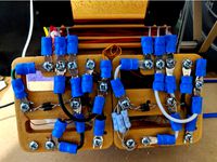
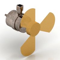
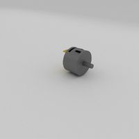
Magnetically Levitated Bedini/Cole Window Pulse Motor by Cotton80
by Thingiverse
Last crawled date: 3 years, 5 months ago
Pulse motors produce little to no heat on the coils when properly wired. That makes pla or abs acceptable materials to make them.
John Bedini and Ron Cole used a solid state circuit along with a configuration of wire (induction coil) along the center of a motor shaft to create what was coined the Bedini/Cole Window motor. This is a highly efficient pulse motor that has an adequate amount of torque to do some usable work. John Bedini rigorously experimented with this technology for over several decades building on the work of others that paved the path before such as Tesla. I believe that he was a genius when it came to electronic circuits. He has held several patents in this work. To do a browser search of the name Bedini brings a wealth of information. He worked with the moderators of this forum: http://www.energyscienceforum.com/forum.php which is a great place to start the journey for learning.
This particular motor/energizer is a fairly simple device that is a tool for learning about radiant energy. Many experiments can be performed with this device.
Disclaimer: This simple device can be very dangerous. Catastrophic failure of parts spinning at high speed can cause damage to property, injury, or even death. There is also a danger of electrical shock. Strong neodymium magnets can cause injury. Build at your own risk.
Parts List:
All magnets were sourced from: http://www.magnet4less.com/
QTY: 32 of .5" X .25" disc magnets for outer magnetic levitation ring
2 ring magnets: 2" outer X 1" inner X .25" depth
6 bar magnets: 2" X .5" X 1/8"
optional for magnetic shaping experiment with rotor: 6 additional 2" X .5" X 1/8"
Those are for the inner slots on the rotor.
4- 12" lengths of 6-32 threaded rod and 8 nuts This is to join the device together.
1/4" smooth rod for the center shaft. I bought a 12" length from VXB Bearings.com
a piece of glass or metal for the pointed end of the shaft or needle to ride against
I use Loctite super glue to secure my parts.
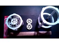
My printed parts are printed on a Printrbot Play with a maximum printing area of 4" X 4" X 5". They are printed in Printrbot Snow White pla. I printed in .2 mm layers, 1.2 mm walls, and .8mm top and bottom layers. Everything was 20% infill except the ring magnet holders. They have 1/8" set screw holes so you should print 50-100% on those two parts.
The wire and pulse circuit is up to you. There is a large variety of options for that.
A circuit such as this: http://www.teslagenx.com/kits/tx-sg4tub.html?category=kits|pcb may be a great place to start.
Please be safe and enjoy!!!! Direct Questions and Comments here: http://www.energyscienceforum.com/showthread.php?t=3380&page=7&p=26245#post26245
https://www.youtube.com/watch?v=p0Tj8U7_qMI
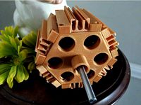
The rotor was redesigned so that the magnets are no longer exposed on the outside.
John Bedini and Ron Cole used a solid state circuit along with a configuration of wire (induction coil) along the center of a motor shaft to create what was coined the Bedini/Cole Window motor. This is a highly efficient pulse motor that has an adequate amount of torque to do some usable work. John Bedini rigorously experimented with this technology for over several decades building on the work of others that paved the path before such as Tesla. I believe that he was a genius when it came to electronic circuits. He has held several patents in this work. To do a browser search of the name Bedini brings a wealth of information. He worked with the moderators of this forum: http://www.energyscienceforum.com/forum.php which is a great place to start the journey for learning.
This particular motor/energizer is a fairly simple device that is a tool for learning about radiant energy. Many experiments can be performed with this device.
Disclaimer: This simple device can be very dangerous. Catastrophic failure of parts spinning at high speed can cause damage to property, injury, or even death. There is also a danger of electrical shock. Strong neodymium magnets can cause injury. Build at your own risk.
Parts List:
All magnets were sourced from: http://www.magnet4less.com/
QTY: 32 of .5" X .25" disc magnets for outer magnetic levitation ring
2 ring magnets: 2" outer X 1" inner X .25" depth
6 bar magnets: 2" X .5" X 1/8"
optional for magnetic shaping experiment with rotor: 6 additional 2" X .5" X 1/8"
Those are for the inner slots on the rotor.
4- 12" lengths of 6-32 threaded rod and 8 nuts This is to join the device together.
1/4" smooth rod for the center shaft. I bought a 12" length from VXB Bearings.com
a piece of glass or metal for the pointed end of the shaft or needle to ride against
I use Loctite super glue to secure my parts.
My printed parts are printed on a Printrbot Play with a maximum printing area of 4" X 4" X 5". They are printed in Printrbot Snow White pla. I printed in .2 mm layers, 1.2 mm walls, and .8mm top and bottom layers. Everything was 20% infill except the ring magnet holders. They have 1/8" set screw holes so you should print 50-100% on those two parts.
The wire and pulse circuit is up to you. There is a large variety of options for that.
A circuit such as this: http://www.teslagenx.com/kits/tx-sg4tub.html?category=kits|pcb may be a great place to start.
Please be safe and enjoy!!!! Direct Questions and Comments here: http://www.energyscienceforum.com/showthread.php?t=3380&page=7&p=26245#post26245
https://www.youtube.com/watch?v=p0Tj8U7_qMI
The rotor was redesigned so that the magnets are no longer exposed on the outside.
Similar models
thingiverse
free
Magnetic Suspension Motor/Generator by Cotton80
...xperiment at your own risk. catastrophic failure of parts spinning at high speed can cause damage to property, injury, or death.
thingiverse
free

Bedini/Cole Window Motor with a Jefimenko electrostatic motor twist by Cotton80
... perfectly. the large round hole can be used for your power cord from a wall-wart or battery pack. there will be more to come;)
thingiverse
free
Pulse Motor(s) for Zero Back emf Experiment by Cotton80
.... you will need to use support on the coil piece and rotor. with the adapter horizontally stacking multiple motors are possible.
thingiverse
free
3D Printed Pulse Energizer For Radiant Energy (5.125" Diameter) by Cotton80
...f the motor ribs but i have found that with my prints they actually just snap in place! pictured in hatchbox gold pla filament.
thingiverse
free

Zero Force Motor Attachment for: http://www.thingiverse.com/thing:2149044 by Cotton80
...=1023
3/5/2017: i added a third option for a rotor. you will be able to fit up to a 3/4" x 3/4" magnet in the slots.
thingiverse
free

Magnet Beam Pulse Motor for Quarter Inch or 8mm Shaft by Cotton80
...his is optional.
the circuit and wire is up to you.
10:24 pm est 02/02/2017: reworked the motor brace to make it easier to print
thingiverse
free

Pulse Motors (Horizontal) for 1/4" or 8mm Shaft by Cotton80
...re. be patient and don't spin too fast as there is a chance that you could yank your wire apart due to the elongated design.
thingiverse
free

"Little Torquey" High Frequency Pulse Energizer by Cotton80
...pt without experience working with electricity. do not operate around equipment that is sensitive to electromagnetic frequencies.
thingiverse
free

Bedini SG style motor (mechanical components) by MrCadillacsts
...tl will be glued to the lower side of the mounting plate.
add your bedini circuit and start the motor!!
have fun with this kit!!!
thingiverse
free
Motor /Generator Stator Casting Mold (7.75" diameter with 12 slots) by Cotton80
...kes m4-.70 x 60 bolts..4 of them)
added stator end caps to hold the wire back..just glue them on with gorilla glue
Cotton80
thingiverse
free
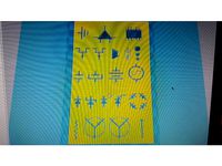
Electronic Symbol Stencils (Basic) by Cotton80
...your pencils. this is two basic stencils to assist with drawing your electronic circuit schematic. they are .8mm thick. enjoy!
thingiverse
free
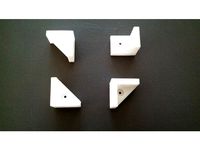
Bracket 3-Point by Cotton80
... to whatever dimensions you like.
disclaimer: use this part in your build at your own risk. load test have not been performed.
thingiverse
free
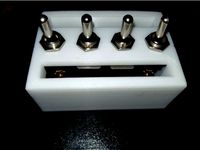
Toggle Switch Mounts (2 or 4) by Cotton80
... in one side for wire access.
also not pictured is 4 mounting holes for 6-32 bolts. they will need to be at least 1.5" long.
thingiverse
free
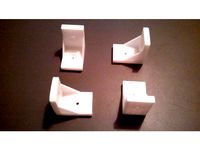
Bracket 90 Degree L by Cotton80
...able tops, securing chair seats
disclaimer: use this part in your creation at your own risk. load test have not been performed.
thingiverse
free
Bedini SSG Solderless Circuit by Cotton80
...elp reduce print time and still remains functional.
i also added a stencil for those who may want to put your circuit on a board.
thingiverse
free
Coupler for 1" Aluminum Square Tube (3-Way) by Cotton80
... support for the two horizontal tube sections.
disclaimer: use this object at your own risk. load test have not been performed.
thingiverse
free
Bearing Hub for PMSM by Cotton80
...en working with electrical equipment, especially when working with capacitors. do not attempt without good electrical knowledge.
thingiverse
free
Magnet Stator for a Mini Windmill Style Generator by Cotton80
...ill bit through the piece to ensure a good fit.
this thing can be scaled up to 200% to fit a 1/2" shaft and 1" magnets.
thingiverse
free

3/4" Rod Holder by Cotton80
...on top to make a light weight shelf. you can use the keyhole hangers to hang pictures in the open instead of directly on a wall.
thingiverse
free
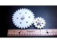
Spur Gears: 1 to 2 Ratio for 1/4" or 8mm shaft by Cotton80
...an easy fit.
the large gear has 28t and the small gear has 14t.
added on 02/05/2017: gears together for 1/4" & 8mm shaft
Bedini
thingiverse
free
Bedini rotor by Syngenta
...ni are in my library. the holes are perfect for 20mm 6mm thick ring magnets.the cover is put onto the magnets for safety reasons.
thingiverse
free

ReDesign3DP Bedini Motor V1 by redesign3dp
...redesign3dp bedini motor v1 by redesign3dp
thingiverse
redesigned bedini motor
thingiverse
free

Bedini Rotor round by Syngenta
...ngenta
thingiverse
this is the round version of my bedini rotor. magnets with 20mm diameter and 7mm in depth fit into the holes.
thingiverse
free

Bedini rotor by Syngenta
...dermagnet-200-x-200-x-30-mm-n45-nickel-m3-senkloch::511.html
(german shop)
coils and other rotors for a bedini are in my library.
thingiverse
free

Optical Tachometer for Bedini 3-pole Kit by liquidbuddha
...istor, with 5mm led plastic holders (both from radio shack). there is a small channel for wires, for the back side led or sensor.
thingiverse
free

Let's make your own Bedini Motor by arnoldkorea
...e spindle)
1 x m3 bolt (m3x50)
8 x m3 bolt (m3x20)
12 x m3 nut
make your own bedini motor circuit and play with fun !!
thingiverse
free
Bedini SSG Solderless Circuit by Cotton80
...elp reduce print time and still remains functional.
i also added a stencil for those who may want to put your circuit on a board.
thingiverse
free

Bedini-Type 6-Pole Magnet Motor by Syrus54
...the size to fit the application.
item is not for sale, royalty free.
[ do not sell nor re-distribute my work ]
you're welcome
thingiverse
free

electric coil by Syngenta
...by syngenta thingiverse this coil is perfect for a bedini pulse motor, the little hole is perfect for 2mm...
thingiverse
free
Bedini SG style motor (mechanical components) by MrCadillacsts
...tl will be glued to the lower side of the mounting plate.
add your bedini circuit and start the motor!!
have fun with this kit!!!
Levitated
turbosquid
$7

Levitation Table
...d
royalty free 3d model levitation table for download as stl on turbosquid: 3d models for games, architecture, videos. (1570956)
turbosquid
$19

Cat levitation. Pendant.
...el cat levitation. pendant. for download as obj, fbx, and stl on turbosquid: 3d models for games, architecture, videos. (1478530)
turbosquid
$15

Small Levitating Lamp
... small levitating lamp for download as max, max, obj, and fbx on turbosquid: 3d models for games, architecture, videos. (1520659)
turbosquid
$10

Levitating Magnetic Globe
... available on turbo squid, the world's leading provider of digital 3d models for visualization, films, television, and games.
3d_ocean
$8

Levitating Skateboard Gadget
...oing on over the forums and is called gadget competition. my inspiration for this gadget was the movie called back to the futu...
turbosquid
$199

Cute levitating robot bot toy
...te levitating robot bot toy for download as max, obj, and fbx on turbosquid: 3d models for games, architecture, videos. (1473303)
turbosquid
$15

levitating wild onions Le plant
... available on turbo squid, the world's leading provider of digital 3d models for visualization, films, television, and games.
turbosquid
$89

German Transrapid Magnetic Levitation High-Speed Monorail Train
... available on turbo squid, the world's leading provider of digital 3d models for visualization, films, television, and games.
3d_export
$12

Sci-fi levitating Monorail 002
...nd lighting. note: there is only 1 set of monorail in this file.for the monorail pole you can download it for free at my profile.
3d_ocean
$15

Lexus Hoverboard 3D model
...pared for photo-realistic renderings, close-ups, cg visualization. the board model is ready to be inserted in your scene out o...
Cole
3ddd
$1

COLE CHAIR BY AMERICAN LEATHER
...le chair by american leather
3ddd
cole , american leather
cole chair by american leather
3ddd
$1

Кресло COLE UMOS Design
...кресло cole umos design
3ddd
cole , umos
кресло cole umos design испания
3ddd
$1

Сапоги Cole Haan
...
высокополигональная модель сапог cole haan. цвет без текстуры, vraycolor. turbosmooth добавлять по желанию для близких рендеров.
3ddd
$1

Cesta, Santa & Cole
...cesta, santa & cole
3ddd
santa&cole
cesta, santa & cole
3ddd
$1
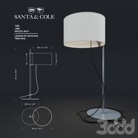
TMD Santa&Cole
...tmd santa&cole
3ddd
santa&cole
настольный светильник tmd santa&cole;
3ddd
$1

FAD / Santa&Cole
...fad / santa&cole
3ddd
santa&cole
настольный светильник fad santa&cole;
3ddd
$1

Cole&Son, Fornasetti
...cole&son, fornasetti
3ddd
cole&son
текстуры cole&son;, коллекция fornasetti
3ddd
$1

Cole&Son, Frontier
...mp;son, frontier
3ddd
cole&son , frontier
обои cole&son;, коллекция frontier
3ddd
$1

Cole&Son, Vivienne Westwood
...cole&son, vivienne westwood
3ddd
cole&son
текстуры cole&son;, vivienne westwood
3ddd
free

Обои Cole & Son, Geometric
...etric , cole&son
50 бесшовных текстур из коллекции geometric от cole & son,
Pulse
3d_export
$6
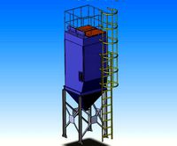
of pulse bag filter
...of pulse bag filter
3dexport
3d model of pulse bag filter
turbosquid
$7

pulse oximeter
...uid
royalty free 3d model pulse oximeter for download as max on turbosquid: 3d models for games, architecture, videos. (1668242)
turbosquid
$25

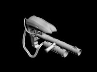
Pulse Cannon
... free 3d model pulse cannon for download as max, fbx, and obj on turbosquid: 3d models for games, architecture, videos. (1559556)
turbosquid
$35

Pulse Grenade
... available on turbo squid, the world's leading provider of digital 3d models for visualization, films, television, and games.
turbosquid
free
pulse canon
... available on turbo squid, the world's leading provider of digital 3d models for visualization, films, television, and games.
3d_ocean
$15

Unmade BED with pulsings
...tal body ,wood base,pulsing elements ,pellows ,unmade bed and all components, all used materials are included sketchup file in...
3d_export
$16

of bag pulse bag filter
...of bag pulse bag filter
3dexport
3d model of bag pulse bag filter
turbosquid
$5

eggy pulse detector
...yalty free 3d model eggy pulse detector for download as sldas on turbosquid: 3d models for games, architecture, videos. (1405234)
3d_export
$10

M4A1-Pulse rifle 3D Model
...m4a1-pulse rifle 3d model
3dexport
alien m4a1 pulse pulserifle rifle
m4a1-pulse rifle 3d model slottet 100562 3dexport
turbosquid
$50

pulse mini gun.blend
... available on turbo squid, the world's leading provider of digital 3d models for visualization, films, television, and games.
Magnetically
3d_ocean
$2

Magnet
...
3docean
3d 3ds max electric magnet magnetic magnetism max model polygon realistic tesla
magnet created in 3ds max by umurdesign.
turbosquid
$6

Magnet
...
turbosquid
royalty free 3d model magnet for download as obj on turbosquid: 3d models for games, architecture, videos. (1548733)
turbosquid
$6

magnet
...uid
royalty free 3d model magnet for download as 3dm and max on turbosquid: 3d models for games, architecture, videos. (1670606)
turbosquid
$1

Magnet
...y free 3d model magnet for download as 3ds, max, obj, and fbx on turbosquid: 3d models for games, architecture, videos. (1215037)
turbosquid
$7

Magnet
...agnet for download as blend, unitypackage, fbx, gltf, and obj on turbosquid: 3d models for games, architecture, videos. (1576588)
3d_export
$5
magnetic knife holder
...magnetic knife holder
3dexport
ordinary magnetic knife holder
archive3d
free

Fridge magnet 3D Model
...t fridge magnet magnet
toy magnetic s n280712 - 3d model (*.3ds) for interior 3d visualization.
turbosquid
$35

Magnetic butterflies
...alty free 3d model magnetic butterflies for download as blend on turbosquid: 3d models for games, architecture, videos. (1315792)
turbosquid
$2

Magnetic Board
...quid
royalty free 3d model magnetic board for download as ma on turbosquid: 3d models for games, architecture, videos. (1264141)
turbosquid
$977

Magnetic Lego
...oyalty free 3d model magnetic lego for download as ma and obj on turbosquid: 3d models for games, architecture, videos. (1142761)
Motor
archibase_planet
free
Motor
...base planet
motor motor engine engine electric motor
motor wagner n250213 - 3d model (*.gsm+*.3ds) for interior 3d visualization.
archibase_planet
free
Motor
...motor
archibase planet
motor motor engine engine
motor n151112 - 3d model (*.gsm+*.3ds) for interior 3d visualization.
archibase_planet
free
Motor
...motor
archibase planet
motor motor engine engine
motor n150615 - 3d model (*.gsm+*.3ds+*.max) for interior 3d visualization.
turbosquid
$15
Motor
...otor
turbosquid
royalty free 3d model motor for download as on turbosquid: 3d models for games, architecture, videos. (1639404)
3d_ocean
$5
Electric motor
...electric motor
3docean
car electric engine industry motor phase train vehicle
an electric motor enjoy!
3d_ocean
$18
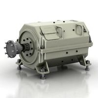
Electric Motor
...electric motor
3docean
electric motor engine machine mover parts
3d model electric motor for hoist crane
turbosquid
$29

Motor
... available on turbo squid, the world's leading provider of digital 3d models for visualization, films, television, and games.
turbosquid
$5
Motor
... available on turbo squid, the world's leading provider of digital 3d models for visualization, films, television, and games.
3d_export
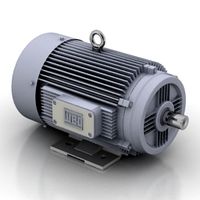
$5
electric motor
...electric motor
3dexport
electric motor use for industrial purposes
3d_export
$5

servo motor
...tor
3dexport
it's a simple part of servo motor 0.75kw for used in machines assembly to show specified motor in own project.
Window
3d_ocean
$3

Window
...window
3docean
window
a lowpoly window .
3d_ocean
$2

Window
...window
3docean
window
a lowpoly window.
3d_ocean
$2

Window
...window
3docean
window
a lowpoly window.
3d_ocean
$2

Window
...window
3docean
window
a lowpoly window .
3d_ocean
$5

Window
...window
3docean
window
a high quality window.
3d_ocean
$4

Window
...window
3docean
window
a high quality window.
3d_ocean
$4

Window
...window
3docean
window
a high quality window.
3d_ocean
$4

Window
...window
3docean
window
a high quality window.
3d_ocean
$3

Window
...window
3docean
window
a high quality window.
3d_ocean
$3

Window
...window
3docean
window
a high quality window .