Thingiverse
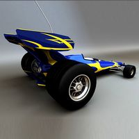
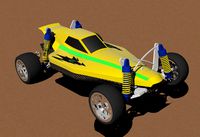
Solar-Powered RC Car with Hub-less Front Wheels by ChisTompso
by Thingiverse
Last crawled date: 2 years, 11 months ago
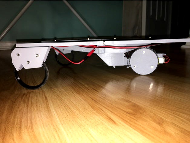
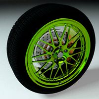
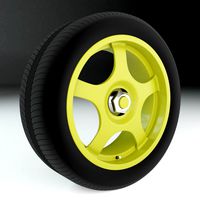
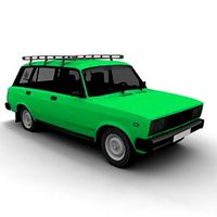
This is a radio controlled solar powered car, that has no wheel hubs for the front wheels. It is a tricycle configuration with two front wheels and one rear wheel. The rear wheel is driven by a single brushed motor, and steered with a single servo in a pull/pull set-up. The solar cells are mounted on the top such that no other vehicle component can cast a shadow on them. The hub-less front wheels use standard M3 bore 3D printer belt pulleys that many users might already have in their spare printer parts collection (which is what inspired this idea).
7/31/2019 - Car is still working great after nearly a year, but noticed it kind of sags where the motor mount interfaces with the steering assembly mount. The reason was I had a 2 mm radius hole for a 1.5 mm radius screw. I have tightened that up to a 1.7mm radius hole (don't want it to be too tight). I've also replaced the copper wire steering lines with 6 lb. test fishing line.
9/8/2018 - Design is complete. The car ran well today with partly cloudy skies. See video below. It does not run well through thick tree shade. Eventually, I plan to experiment with a small battery charging off the cells to power through tree shades along the road in my neighborhood. Overall, it controls and drives quite well. It is not fast, but the motor is geared for torque, not speed, which is what you want to power up hills and over bumps in the road. You’ll notice the top center panels in some of my pictures are a bit bowed. This has been corrected in the .stl files. I shaved 1 mm off each end of these (TopClampV2.stl), so that issue is fixed. Some construction notes:
If you want to pack all of the electronics inside, you need to snip off the ESC switch and solder the wires to close the circuit. You’ll also want to snip the male JST connector from the ESC (since you’ll be soldering to the motor wires anyway). Solder that male JST connector to the front left solar panel. This way, you can connect it to the female JST connector that hangs out of the side of the body. This will allow you to swap out the solar cell for a battery for indoor use or cloudy days.
There are only files uploaded for a left front wheel assembly. For the right side, just tell your slicer to mirror the left files.
Solar cells are wired together in parallel. Individual cells provide sufficient voltage, but multiple cells in parallel are required to provide the necessary current. When you solder them, take care to note which corner you need the JST connector, and where you'll locate the left-to-right cross-over wire. There is a cut-out int he top of the body (Spine.stl) to accommodate that wire cross-over.
8/24/2018 - Printed one of the frame quadrants. Solar cell didn't fit. That's what I get for not doing a fit check in the model. Anyway, got that fixed, and updated SolarCellFrameV2.
8/18/2018 - Initial design complete. Now to assemble, test, and tweak!
8/15/2018 - Designed the servo mount for steering. Added the latest top level assembly photo to reflect that.
8/13/2018 Update - Surprisingly, the first version of the motor mount worked like a charm with no design revisions needed. Solar cell mounting frame design is now in-work. Added an incomplete top-level assembly picture to show where the overall layout is headed. Still need to design the center primary core frame to tie it all together, but coming along nicely.
8/10/2018 Update - Added the motor mount and a FreeCad screen snip of the Control Assembly, which includes the motor, motor mount, and drive wheels. The two tabs on the front of the motor mount will be for pull/pull control wires to the steering servo.
8/6/2018 Update - Wheel assembly design is complete (see new pics). All prototypes wheel assemblies fit and function properly. I'll likely reduce the screws required to hold the aft drive wheel assembly together from 4 to 3, but that's minor. Now time to design the main body frame and steering mechanism! Debating if I want this thing to have batteries for driving through shady areas or not... Maybe I'll at least add provisions for the future growth.
PARTS! PARTS! PARTS!!!!
All parts listed below are from Amazon
*4 Solar Cells - ALLPOWERS 2 Pieces 2.5W 5V/500mAh Solar Panel DIY Battery Charger Kit Mini Encapsulated Solar Cell Epoxy for Battery Power LED 130x150mm (Solar Panel Only)
*1 ESC - Hobbypower Rc ESC 10a Brushed Motor Speed Controller for Rc Car Boat W/o Brake
*1 Brushed Motor - Doradus 5Pcs DC 3V-6V Dual Axis Gear Reducer Motor For Arduino Smart Car
*6 Belt Pulleys - WINSINN 2GT GT2 Aluminum Timing Belt Idler Pulley 20 Toothless 3mm Bore For 3D Printer 6mm Width Timing Belt (Pack of 5Pcs)
*1 Servo Actuator - ElectroBot 2X Pcs Sg90 Micro Servo Motor 9G Rc Robot Helicopter Airplane Boat Controls
*Miscellaneous M3 screws, nuts, and washers + wire, solder, heat shrink, etc.
Similar models
3dwarehouse
free

Arduino powered servo-steer basic layout
...ut for a arduino controlled rc car with rear wheel power and front whell servo-steering #arduino #draft #layout #radio #rc #robot
grabcad
free

3D Printed RC Car
...d rc car 2wd with front wheels servo steering.
arduino uno, rc bluetooth, ultrasonic sensor, 2 wheel motors, sg90 servo steering.
thingiverse
free

3D Printed Arduino RC CAR by Pammeg80
...d rc car 2wd with front wheels servo steering.
arduino uno, rc bluetooth, ultrasonic sensor, 2 wheel motors, sg90 servo steering.
grabcad
free

RC Car
...or steering and is equipped with a gearbox to power the rear wheels. additionally, a small dc motor is housed inside the gearbox.
thingiverse
free

Servo mounts by aub
...rvo (in this case, an hs-322 hd), but the original control was screwed in vertically while the servo needed horizontal fasteners.
thingiverse
free

RC wire seperators 1/10 scale by tormies
...tors 1/10 scale by tormies
thingiverse
wire combs for 1/10 scale rc cars. perfect for motor wires, battery leads, and esc wires.
thingiverse
free

Servo conversion for 1/14 Rastar Porsche Cayenne
...any 1/16 brushed esc will fit next to a receiver on top of the motor/gearbox assembly. use 3m vhb tape so you can move and tweak.
thingiverse
free

Linear Servo Mount
...or terminals. this bypasses the electronics and made the motor usable with just two aaa batteries and a momentary toggle switch.
thingiverse
free

servo controlled SOLDERING FUME EXTRACTOR
... servo tester, and neopixle led strip. and can be powered from a portable battery charger.
this mount fits an 80mm computer fan.
thingiverse
free

3D Printed RC Car / Buggy | PLA by ahmetakifkaya22
...parts are 3d printed in pla. this one has similar dimensions to a 1/10th scale rc car. technical specifications:...
Chistompso
thingiverse
free

Caps For Do Nothing Machine by ChisTompso
... with a hammer to get them down the final 2 millimeters, which is good because they have a nice snug fit with no glue or threads.
thingiverse
free

Garden Flag Pole Keep by ChisTompso
...inal freecad files so you can tweak as needed for your use. it is designed to be tight on 7mm, with a notch to allow it to flex.
thingiverse
free

M.A.X. Truck - Front Bumper by ChisTompso
...ly sacrificial, protection going forward. time will tell... my wife thinks it looks like a mustache. i can't unsee it now.
thingiverse
free

M.A.X. Truck - Trailer by ChisTompso
...his trailer:
rocket launcher https://www.thingiverse.com/thing:4626829
as always, let me know if you have any questions! enjoy!
thingiverse
free

Yi Dome Camera Inverted Wall Mount by ChisTompso
...t;yicammount-singlepiece.stl."
you can use the same screws that the camera came with to attach the camera mount to the wall.
thingiverse
free

FPV Prototank with Turret by ChisTompso
...-you'll also need wire, solder, tweezers, soldering iron... you know... all of the basics for working with hobby electronics.
thingiverse
free

M.A.X. Truck - Mobile Launch Vehicle Trailer by ChisTompso
...ddler runs the nest and dictates where engineering resources are directed. m.a.x. truck garbage truck accessory coming next...
Hub
3d_export
free

hub
...hub
3dexport
realistic 3d model of hub. you can use this model in your automotive or mechanical projects.
design_connected
$4

Hub 02
...hub 02
designconnected
glas italia hub 02 dining tables computer generated 3d model. designed by piero lissoni.
turbosquid
$8

Electricity Hub
...id
royalty free 3d model electricity hub for download as fbx on turbosquid: 3d models for games, architecture, videos. (1298030)
turbosquid
$2

Gokart Hub
...bosquid
royalty free 3d model gokart hub for download as ige on turbosquid: 3d models for games, architecture, videos. (1497617)
turbosquid
free

Desert hub
...squid
free 3d model desert hub for download as blend and fbx on turbosquid: 3d models for games, architecture, videos. (1634736)
design_connected
$18

UMBRA Hub Ladder
...umbra hub ladder
designconnected
umbra hub ladder computer generated 3d model.
turbosquid
$48

hub-dxf
... available on turbo squid, the world's leading provider of digital 3d models for visualization, films, television, and games.
turbosquid
$25

Shoulder Hub
... available on turbo squid, the world's leading provider of digital 3d models for visualization, films, television, and games.
turbosquid
$20

BMX Hub
... available on turbo squid, the world's leading provider of digital 3d models for visualization, films, television, and games.
3d_ocean
$5

Stairwell Hub
... is a low polygonal model. - poly count: 323 - formats: max /obj /fbx/3ds/dxf - high detail was preserved with 2048×2048 textu...
Solar
3d_ocean
$4

Solar Panel
...solar panel
3docean
cell panel solar
fully textured solar panel with scaleable solar cells.
3ddd
$1
solar cell
...solar cell
3ddd
солнечная батарея
solar cell
3d_export
$7

Solar Panel
...solar panel
3dexport
perfect solar panel for roof, modular, extensible.
3d_export
$5

solar system
...solar system
3dexport
solar system in c4d, with 8k nasa textures
3d_export
$15
solar system
...nd the other the sun, the earth and the moon, the latter has an animation with camera movement included, the files are in spanish
3ddd
$1
Zumtobel Solar II
...obel solar ii
3ddd
zumtobel , solar
модель направленного светильника solar 2 от zumtobel
3d_ocean
$14
Solar Panels
... materials, hdri map, vray gi setup. four solar panels: type1: 1849 – poly, 2035 – vert. type2: 954 – poly, 1051 – vert. type3...
turbosquid
$29

Solar System
...squid
royalty free 3d model solar system for download as fbx on turbosquid: 3d models for games, architecture, videos. (1236050)
turbosquid
$25
Solar Panel
...osquid
royalty free 3d model solar panel for download as max on turbosquid: 3d models for games, architecture, videos. (1516562)
turbosquid
$25
Solar System
...uid
royalty free 3d model solar system for download as blend on turbosquid: 3d models for games, architecture, videos. (1314058)
Rc
3ddd
$1
RC Helicopter
...rc helicopter
3ddd
вертолет
mini rc helicopter
93.329 polys
3d_export
$7
rc helicopter model
...rc helicopter model
3dexport
rc helicopter model
3d_ocean
$25
RC F1
...rc f1
3docean
auto car control f1 formula race rc remote speed
remote control f1 car
turbosquid
$10
rc plane
...lane
turbosquid
free 3d model rc plane for download as blend on turbosquid: 3d models for games, architecture, videos. (1295828)
turbosquid
$100
RC Helicopter
...free 3d model rc helicopter for download as 3ds, max, and obj on turbosquid: 3d models for games, architecture, videos. (1298511)
turbosquid
$59

Drone with RC
...3d model drone with rc for download as 3ds, max, obj, and fbx on turbosquid: 3d models for games, architecture, videos. (1363601)
turbosquid
$75
RC buggy
... available on turbo squid, the world's leading provider of digital 3d models for visualization, films, television, and games.
turbosquid
$39

RC Plane001
... available on turbo squid, the world's leading provider of digital 3d models for visualization, films, television, and games.
turbosquid
$30
RC Jet
... available on turbo squid, the world's leading provider of digital 3d models for visualization, films, television, and games.
turbosquid
$30
Rc airplane
... available on turbo squid, the world's leading provider of digital 3d models for visualization, films, television, and games.
Less
design_connected
free

Less
...less
designconnected
molteni & c less free models computer generated 3d model. designed by jean nouvel.
3d_export
$10

Two Less tables 3D Model
...two less tables 3d model
3dexport
less molteni molteni&c table desk model
two less tables 3d model boroda 56653 3dexport
3d_export
$7

MolteniC table Less 3D Model
...c table less 3d model
3dexport
table desk molteni molteni&c less model
moltenic table less 3d model boroda 56651 3dexport
3d_export
$7

MolteniC table Less 3D Model
...c table less 3d model
3dexport
table desk molteni molteni&c less model
moltenic table less 3d model boroda 56650 3dexport
turbosquid
$19

Cisal Less New set
...3d model cisal less new set for download as max, obj, and fbx on turbosquid: 3d models for games, architecture, videos. (1470676)
turbosquid
$19

European Modern Couch - Less
...an modern couch - less for download as max, obj, fbx, and dwg on turbosquid: 3d models for games, architecture, videos. (1281460)
turbosquid
$4

Broom plastic less poly
... available on turbo squid, the world's leading provider of digital 3d models for visualization, films, television, and games.
design_connected
$13

ANNA TORFS Parts Low Less Sculpture Vases
...anna torfs parts low less sculpture vases
designconnected
anna torfs parts low less sculpture vases computer generated 3d model.
turbosquid
$15

Ikea set MALSJO LESS chest of drawers
...alsjo less chest of drawers for download as max, obj, and fbx on turbosquid: 3d models for games, architecture, videos. (1607005)
turbosquid
$450

Ear less semi-automatic N95 mask machine Assembly
... semi-automatic n95 mask machine assembly for download as max on turbosquid: 3d models for games, architecture, videos. (1559662)
Front
archibase_planet
free

Front
...front
archibase planet
facade front bluff
front 3d01a - 3d model (*.gsm+*.3ds) for interior 3d visualization.
3d_export
$5
front fork
...front fork
3dexport
front fork
3d_export
$5
Front Desk
...front desk
3dexport
modern and minimal reception front desk
3d_ocean
$4
Medical Front
...medical front
3docean
horror low medical
medical front
3d_ocean
$5
Front Desk
...front desk
3docean
desk front office reception
office reception counter or front desk. cad file and obj file included.
3ddd
free

Axor WaterDream by Front
...r , waterdream , front
axor waterdream by front
3d_export
$5
front nut eye
...front nut eye
3dexport
front nut eye
3d_export
$5
front screw eye
...front screw eye
3dexport
front screw eye
3d_export
$5

front clamping device
...front clamping device
3dexport
front clamping device
archive3d
free
Front 3D Model
...rchive3d
facade front bluff
front 3d01a - 3d model (*.gsm+*.3ds) for interior 3d visualization.
Powered
turbosquid
$100
power
...ower
turbosquid
royalty free 3d model power for download as on turbosquid: 3d models for games, architecture, videos. (1421990)
3d_export
$5

Power
...power
3dexport
3d_export
$5
power outlets
...power outlets
3dexport
power outlets
3ddd
$1
lion power
...lion power
3ddd
лев , статуя
lion power gold sculpture
3ddd
$1
Sea Power
...
компас , море , часы
часы с компасом sea power
3ddd
free
Meridiani / Power
...power
3ddd
meridiani , круглый
стол power производитель meridiani, диаметр 120,высота 67
3d_export
$5

Power Surge
...power surge
3dexport
the power surge is a all mesh carnival ride to lower in game part count and lag
turbosquid
$8
Airport Ground Power Unit (AXA Power )
... available on turbo squid, the world's leading provider of digital 3d models for visualization, films, television, and games.
turbosquid
$50

Power Houser
...rbosquid
royalty free 3d model power houser for download as on turbosquid: 3d models for games, architecture, videos. (1333800)
3d_export
$5

power outlet
...power outlet
3dexport
power outlet<br>format file maya 2018, 3d max 2017, obj, fbx
Wheels
archibase_planet
free

Wheel
...l steering control steering wheel
wheel ship steering wheel n060215 - 3d model (*.gsm+*.3ds+*.max) for exterior 3d visualization.
3d_ocean
$14
Wheel
...wheel
3docean
car rim car wheel rim wheel
high poly car wheel design. 16,840 polys
3d_export
free

wheel
...wheel
3dexport
wheel
3d_export
free
wheel
...wheel
3dexport
wheel
3d_export
free
Wheel
...wheel
3dexport
wheel
3d_export
$5

wheel
...wheel
3dexport
wheel for car.
3d_export
$5
wheel
...wheel
3dexport
car wheel
3d_export
$5
wheel
...wheel
3dexport
car wheel
3d_export
$5
wheel
...wheel
3dexport
car wheel
3d_export
$5

wheel
...wheel
3dexport
car wheel
Car
3d_export
$5

car
...car
3dexport
luxury car high quality car
3d_export
$5

car
...car
3dexport
luxury car high quality car
3d_export
$5

car
...car
3dexport
luxury car high quality car
3d_export
$5

car
...car
3dexport
luxury car high quality car
3d_export
$5
car
...car
3dexport
luxury car high quality car
archibase_planet
free
Car
...
archibase planet
car sports car motor-car sportster
car nascar#1 n300114 - 3d model (*.gsm+*.3ds) for exterior 3d visualization.
archibase_planet
free

Car
...ibase planet
car motor-car sportster sports car
car gablota xform n190214 - 3d model (*.gsm+*.3ds) for exterior 3d visualization.
archibase_planet
free
Car
...car
archibase planet
car motor car transport
car vaz 2104- 3d model for interior 3d visualization.
3d_export
$15

car
...car
3dexport
car
3d_export
free
car
...car
3dexport
car