Thingiverse
Prusa i3 MK3 PiCam v2 X-Axis Motor Mount by jppowers
by Thingiverse
Last crawled date: 3 years ago
Prusa i3 MK3 PiCam v2 X-Axis Motor Mount
What is this?
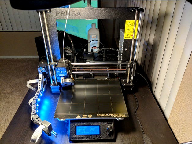
The goal here is to mount a Raspberry Pi Camera v2 to the X-Axis motor of the Prusa Research Prusa i3 MK3. This will allow the camera to move up the Z axis as printing, which should make for nice time lapse videos and allow a visual of the extruder while checking the live feed to look for potential issues.
The arm is thickened significantly compared to others to allow for a couple of ~10mm wide (so a total of ~20mm wide) LED light strips to be attached directly to the arm. This should provide a much more even casting of light across the printed part.
Where did it come from?
I like the idea of the X axis motor mounted camera arm from dragsterbox here and the arm extender from Mososokruppe here, and it's currently printed out and ready to go for my use (I printed a couple of Mososokruppe's extenders actually), just waiting on a PiCam ribbon I ordered that (should) be long enough to show up. While I was test fitting the parts I thought about how the print area will be lit, and while goofing around with my desk lamp realized some LED light strips might make the difference I'm looking for.
What's the plan here?
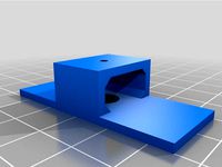
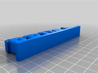
The cut outs in the arm are intended for zip ties to keep the LED strips in place (I never trust the stickiness of the tape on the back of these long term), although it should help reduce the mass of the arm a bit, too. I threw together a pretty generic mounting bracket system to connect the arms together: a couple holes for using screws and nylock nuts. An M3 screw should work for connecting each arm together, 16 to 20mm long. I considered placing an M3 nut cut out but decided against it, as leaving it "free floating" should allow for much easier minor adjustments to the camera angles. I kept dragsterbox's PiCam enclosure and rotating mount, and used the shape of his mounting arm as a guide for the main arm here.
Parts:
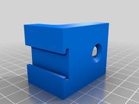
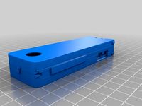
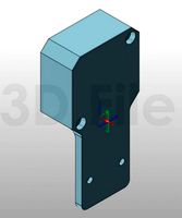
Main arm: Required, mounts to the X Axis motor so the camera moves up the Z axis as printing.
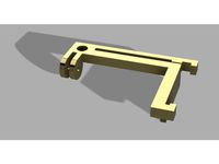
Extender: Optional, I prefer the camera being a bit further out from the bed and closer to the front left corner of the bed.
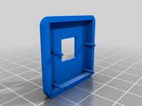
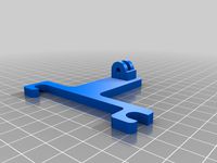
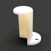
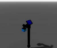
Camera mount arm: Required, this is where the camera sits. This arm is shaped a bit differently on the end to allow dragsterbox's enclosure and rotating mount.
4: Camera case and mount: This is dragsterbox's enclosure and mount directly, including for ease of download.
5: "Altogether": A couple STL's of the parts for the arm all together (if you already have dragsterbox's stuff printed), and another of all the parts together.
M3 20mm screws and M3 nylock nuts: These will be used to connect the arm segments together. 16mm might work for some spots.
LED Strips: The LED strips I got are from Fry's, Omni Lighting Systems Home Accent Series Kits. I got a Y split/extension cable to go with it, and the plan is to route the extension cable around the back of the arms, down the frame, and out the back to it's control box/power adapter. Almost any LED strip of the right length should work here as long as it's flexible and 10-20mm thick. I'm doubling up on the 10mm strips to increase the amount of light. RGB definitely isn't necessary but a nice to have in my opinion as different color filament might look nicer with different lighting.
Depending on where you mount your Pi, a decently long PiCam ribbon cable. Mine is 1 meter. Amazon link: (http://a.co/d/ipKorKB)[http://a.co/d/ipKorKB] I could have gone shorter, but I'd prefer having a tiny bit more slack than necessary than not enough.
Notes
Rev1 parts keep the camera lower and provides an excellent view of the extruder. Rev2 brings the camera up high enough so it's looking down at the build plate more. Rev1 is great for checking a live feed to ensure things are printing right, Rev2 is better for timelapses. I can't help but recommend printing both, try them out and see how you feel about it.
Print settings
My Slic3rPE settings:
For the arms: 3 perimeters, 30% infill. I want the arms themselves to be rigid. STL's should be setup so the arms print flat, which keeps the layer lines running in a way that should help reduce seperation due to vibrations and hold up to types of motion it should experience. No supports are necessary in this orientation, either.
For the camera parts: I'd do 2 perimeters and 10-20% infill, whatever floats your boat (or 3DBenchy... eh? eh? Bad joke? K I'll see myself out)
What's pictured
To start, I didn't notice until after I started uploading the pictures of it mounted that one of the LED strips was off. It was plugged in wrong. Whoops! Fixed it, and you may guess but it's a good bit brighter now.
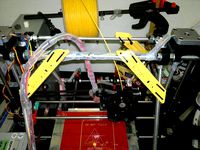
Front view of camera with arm fully installed and functioning (ignoring that one LED strip that I didn't plug in right).
Timelapse recorded with Rev1 installed: https://youtu.be/AeQpy1RO2DE
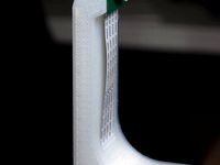
Here you can see the slack in the PiCam ribbon at the joints better.
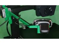
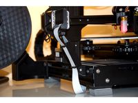
Wider shot of the arm and my attempt at managing the cabling.
I try to keep wiring as tidy as possible but the PiCam's ribbon doesn't like being tied up when moving up and down the Z Axis. I let it hang loose and tried to keep everything else tighter.
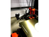
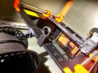
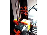
Pictured during install, ths is my test fitting.
To reduce confusion hopefully, here's the exact placement of each arm segment.
Another picture during test fitting.
I'm likely going to raise this camera mount position all the way up to regain that few millimeters worth of camera angle. I didn't think the LED strip would extend so far out with the slack I was hoping to give it at the joints but ultimately I prefer having lighting right under the camera to hopefully give it more direct lighting at what it's pointing at.
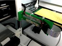
This is testing the LED's to ensure they were working and also trying to route the cables as smartly as possible. These strips are bright enough I didn't notice only one was on.
View from Octoprint Control tab during the first layer of my first print after installing.
What is this?
The goal here is to mount a Raspberry Pi Camera v2 to the X-Axis motor of the Prusa Research Prusa i3 MK3. This will allow the camera to move up the Z axis as printing, which should make for nice time lapse videos and allow a visual of the extruder while checking the live feed to look for potential issues.
The arm is thickened significantly compared to others to allow for a couple of ~10mm wide (so a total of ~20mm wide) LED light strips to be attached directly to the arm. This should provide a much more even casting of light across the printed part.
Where did it come from?
I like the idea of the X axis motor mounted camera arm from dragsterbox here and the arm extender from Mososokruppe here, and it's currently printed out and ready to go for my use (I printed a couple of Mososokruppe's extenders actually), just waiting on a PiCam ribbon I ordered that (should) be long enough to show up. While I was test fitting the parts I thought about how the print area will be lit, and while goofing around with my desk lamp realized some LED light strips might make the difference I'm looking for.
What's the plan here?
The cut outs in the arm are intended for zip ties to keep the LED strips in place (I never trust the stickiness of the tape on the back of these long term), although it should help reduce the mass of the arm a bit, too. I threw together a pretty generic mounting bracket system to connect the arms together: a couple holes for using screws and nylock nuts. An M3 screw should work for connecting each arm together, 16 to 20mm long. I considered placing an M3 nut cut out but decided against it, as leaving it "free floating" should allow for much easier minor adjustments to the camera angles. I kept dragsterbox's PiCam enclosure and rotating mount, and used the shape of his mounting arm as a guide for the main arm here.
Parts:
Main arm: Required, mounts to the X Axis motor so the camera moves up the Z axis as printing.
Extender: Optional, I prefer the camera being a bit further out from the bed and closer to the front left corner of the bed.
Camera mount arm: Required, this is where the camera sits. This arm is shaped a bit differently on the end to allow dragsterbox's enclosure and rotating mount.
4: Camera case and mount: This is dragsterbox's enclosure and mount directly, including for ease of download.
5: "Altogether": A couple STL's of the parts for the arm all together (if you already have dragsterbox's stuff printed), and another of all the parts together.
M3 20mm screws and M3 nylock nuts: These will be used to connect the arm segments together. 16mm might work for some spots.
LED Strips: The LED strips I got are from Fry's, Omni Lighting Systems Home Accent Series Kits. I got a Y split/extension cable to go with it, and the plan is to route the extension cable around the back of the arms, down the frame, and out the back to it's control box/power adapter. Almost any LED strip of the right length should work here as long as it's flexible and 10-20mm thick. I'm doubling up on the 10mm strips to increase the amount of light. RGB definitely isn't necessary but a nice to have in my opinion as different color filament might look nicer with different lighting.
Depending on where you mount your Pi, a decently long PiCam ribbon cable. Mine is 1 meter. Amazon link: (http://a.co/d/ipKorKB)[http://a.co/d/ipKorKB] I could have gone shorter, but I'd prefer having a tiny bit more slack than necessary than not enough.
Notes
Rev1 parts keep the camera lower and provides an excellent view of the extruder. Rev2 brings the camera up high enough so it's looking down at the build plate more. Rev1 is great for checking a live feed to ensure things are printing right, Rev2 is better for timelapses. I can't help but recommend printing both, try them out and see how you feel about it.
Print settings
My Slic3rPE settings:
For the arms: 3 perimeters, 30% infill. I want the arms themselves to be rigid. STL's should be setup so the arms print flat, which keeps the layer lines running in a way that should help reduce seperation due to vibrations and hold up to types of motion it should experience. No supports are necessary in this orientation, either.
For the camera parts: I'd do 2 perimeters and 10-20% infill, whatever floats your boat (or 3DBenchy... eh? eh? Bad joke? K I'll see myself out)
What's pictured
To start, I didn't notice until after I started uploading the pictures of it mounted that one of the LED strips was off. It was plugged in wrong. Whoops! Fixed it, and you may guess but it's a good bit brighter now.
Front view of camera with arm fully installed and functioning (ignoring that one LED strip that I didn't plug in right).
Timelapse recorded with Rev1 installed: https://youtu.be/AeQpy1RO2DE
Here you can see the slack in the PiCam ribbon at the joints better.
Wider shot of the arm and my attempt at managing the cabling.
I try to keep wiring as tidy as possible but the PiCam's ribbon doesn't like being tied up when moving up and down the Z Axis. I let it hang loose and tried to keep everything else tighter.
Pictured during install, ths is my test fitting.
To reduce confusion hopefully, here's the exact placement of each arm segment.
Another picture during test fitting.
I'm likely going to raise this camera mount position all the way up to regain that few millimeters worth of camera angle. I didn't think the LED strip would extend so far out with the slack I was hoping to give it at the joints but ultimately I prefer having lighting right under the camera to hopefully give it more direct lighting at what it's pointing at.
This is testing the LED's to ensure they were working and also trying to route the cables as smartly as possible. These strips are bright enough I didn't notice only one was on.
View from Octoprint Control tab during the first layer of my first print after installing.
Similar models
thingiverse
free
Cable Channel LED Strip Mount by b14ckyy
...ecommend printing transparent.
fits to cable channel up to 20mm wide.
hole for screw and screwdriver inserted for easy mounting.
thingiverse
free
CR-6 SE C270 No Modifcation Camera Mount by ThingaUser
...ll of the x-axis movement for prints should be visible, and i have added a spot for a cable tie to keep the cable out of the way.
thingiverse
free
PiCam 1.3 Case for 3D Printer by lainchy
...this should allow slack.
i have held my case together with a small amount of tape, but a blob of glue on each pin should be fine.
thingiverse
free
Raspberry Pi Camera Module V2 Mount With Ribbon Attachment by abogdal
... attachment
it's a remix of https://www.thingiverse.com/thing:4332289.
this version adds picam ribbon attachment to the arm.
thingiverse
free

Anet heatbed RPi camera arm by plowna
...th wavesupportapparatus's ribbon cable clip (here), so the cable can be kept out of the way. will update with photos shortly.
thingiverse
free

Tough RasPi Camera mount for Printrbot Simple Metal by WaveSupportApparatus
... the side of this mount and three onto the side of the simple's bed to route the camera's cable away from the print area.
thingiverse
free

CR10V2 X-axis mount for picam v2 by schmooot
...lready had a long one but i see now i'll have to get an even longer one if i want to print anything tall or over to one side.
thingiverse
free
Raspberry Pi Camera mount arm by whttigress
...s to create a mount to attach the raspberry pi camera. it attaches with a bolt through the plywood that is the base of my y axis
thingiverse
free
Camera mount extender for Prusa MK3 by Mososokruppe
...art of the extender.
in my pictures, i am using a different camera case, though i plan to switch to the one from the source file.
thingiverse
free
MP Select Mini Raspberry Pi Camera holder with LED's by jschmall
...nation of zip ties and hot glue to secure everything to the gantry.
i've also included a mount without the camera attachment.
Jppowers
thingiverse
free

Rainbow Six Seige Ban Hammer by jppowers
... the handle will handle being scaled up well but i imagine it should, i highly doubt it can scale down but much if at all though.
thingiverse
free

Pokemon Go Universal Aimer - Mk5 by jppowers
...lly loctite fun-tak mounting putty (http://smile.amazon.com/dp/b001f57zpw) and it works really well. very happy with the results.
thingiverse
free

GT86/FRS/BRZ center console organizer REMIX by jppowers
... mk3s fits it just barely, and i think a 200mm x 200mm bed might fit it if you spin it 45 degrees. cutting it half may work, too.
thingiverse
free

Dell WD19TB Dock Stand with 120mm fan by jppowers
...ts to "fasten" the dock in place so the weight of the cables that plug into the dock don't tilt it around too much.
thingiverse
free

Prusa i3 MK3 PiCam v2 X-Axis Motor Mount REMIX - With Diffuser by jppowers
...b led strips this time around: https://smile.amazon.com/gp/product/b07nwfvry4/ref=ppx_yo_dt_b_search_asin_title?ie=utf8&psc=1
Picam
thingiverse
free
Picam Holder
... holder
thingiverse
this is a picam holder compatible with the modular mounting system https://www.thingiverse.com/thing:2194278
thingiverse
free

picam hypercube by marko87
...picam hypercube by marko87
thingiverse
support pour picam hypercube evolution
thingiverse
free
PiCam 2 Focus tool
...picam 2 focus tool
thingiverse
focus tool for the picam 2
thingiverse
free
Picam support for Ender 3
...picam support for ender 3
thingiverse
picam support for ender 3 printer.
based on octoprint support.
printed in pla, no supports
thingiverse
free

PiCam SG90 servo mount by Inventoteca
...picam sg90 servo mount by inventoteca
thingiverse
mount the picam rev 1.3 to a sg90 servo.
thingiverse
free
Support GoPro/Picam Ender 3
...support gopro/picam ender 3
thingiverse
support de camera gopro ou picam
thingiverse
free
360 PiCam Zero by ssaratks
...e
the model was designed to provide a 360 view of the picam. it has two versions,
with snap lock system
without snap lock system
thingiverse
free
CR6 SE PiCam Right Mount by evotodi
...avel.
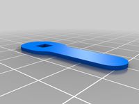
try this wrench.
2021-03-24: there is a new updated version coming out soon with an articulated arm for better positioning.
thingiverse
free
The Mountster for PiCam by enekomontero
...erse
the camera can be screwed in place using the two holes on the side of the lens and there is an opening for the focus light.
thingiverse
free

Zortrax Raspberry PiCam support by swatre
...not for octopi not compatible with zortrax.
other parts to fix the raspberry pi on zortraxhttp://www.thingiverse.com/thing:611270
Mk3
turbosquid
$50
cention mk3
...ty free 3d model cention mk3 for download as ma, obj, and fbx on turbosquid: 3d models for games, architecture, videos. (1454148)
turbosquid
$129
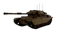
MK3 Tank
... available on turbo squid, the world's leading provider of digital 3d models for visualization, films, television, and games.
turbosquid
$100
Toyota Supra MK3
... available on turbo squid, the world's leading provider of digital 3d models for visualization, films, television, and games.
turbosquid
$44
cention mk3 low poly
...d model cention mk3 low poly for download as ma, obj, and fbx on turbosquid: 3d models for games, architecture, videos. (1454666)
turbosquid
$30

Challenger I Mk3 Falcon
... available on turbo squid, the world's leading provider of digital 3d models for visualization, films, television, and games.
turbosquid
$10

American Frag hand grenade MK3
...free 3d model american frag hand grenade mk3 for download as on turbosquid: 3d models for games, architecture, videos. (1393624)
turbosquid
$20
Mk3 US Navy Combat Knife
...ty free 3d model mk3 us navy combat knife for download as fbx on turbosquid: 3d models for games, architecture, videos. (1172791)
3d_export
$29

Ford Fiesta MK3 Modified 3D Model
...7 tumerfx mtumer mehmet t?mer 1993 1995 1996 wrc special modifed modifiye
ford fiesta mk3 modified 3d model mtumer 30698 3dexport
3d_export
$99

Toyota Supra Mk3 19861993 3D Model
...ort fast coupe japan 1986 1987 1988 1989 1990 1991 1992 1993 tuning turbo
toyota supra mk3 19861993 3d model squir 62530 3dexport
turbosquid
$5

Timothy Oulton Mars Chair MK3
...on mars chair mk3 for download as 3ds, max, obj, fbx, and dae on turbosquid: 3d models for games, architecture, videos. (1209782)
I3
3d_export
$10
suv i3
...suv i3
3dexport
suv i3 2013 series
3d_ocean
$89

BMW i3 2012
...y, in real units of measurement, qualitatively and maximally close to the original. model formats: - *.max (3ds max 2008 scanl...
cg_studio
$99

BMW i3 20143d model
...
cgstudio
.3ds .c4d .fbx .lwo .max .obj - bmw i3 2014 3d model, royalty free license available, instant download after purchase.
cg_studio
$99

BMW i3 20123d model
...tudio
.3ds .c4d .fbx .lwo .max .mb .obj - bmw i3 2012 3d model, royalty free license available, instant download after purchase.
cg_studio
$99

BMW i3 20143d model
...tudio
.3ds .c4d .fbx .lwo .max .mb .obj - bmw i3 2014 3d model, royalty free license available, instant download after purchase.
humster3d
$75
3D model of BMW i3 2014
...
buy a detailed 3d model of bmw i3 2014 in various file formats. all our 3d models were created maximally close to the original.
humster3d
$40

3D model of Kitchen Set I3
...uy a detailed 3d model of kitchen set i3 in various file formats. all our 3d models were created maximally close to the original.
3d_ocean
$30
Kitchen set i3
...ensils oven plates shelves sink table ware
kitchen set i3 include 3d models: cooker, oven, sink, cupboards, table, chair, plates.
3d_ocean
$89

BMW i3 2014
...y, in real units of measurement, qualitatively and maximally close to the original. model formats: - *.max (3ds max 2008 scanl...
cg_studio
$99

BMW i3 Concept 20113d model
...i3
.3ds .c4d .fbx .lwo .max .obj - bmw i3 concept 2011 3d model, royalty free license available, instant download after purchase.
Prusa
turbosquid
$2
Frame Filament Guide Clip-On for Prusa Mk3
...rame filament guide clip-on for prusa mk3 for download as stl on turbosquid: 3d models for games, architecture, videos. (1634730)
3d_export
free
prusa i3 mk3s laser mount for opt lasers
...to learn more about the blue laser technology that conceived the cutting and engraving laser heads from opt lasers, please visit:
turbosquid
free
Prusa small printer adapter holder
...er for download as ipt, skp, dwg, dxf, fbx, ige, obj, and stl on turbosquid: 3d models for games, architecture, videos. (1642936)
3d_export
$30

geisha by jonathan adler
...** i did a 3d printing test in the prusa software, you can find it among the attached images.<br>exchange:<br>.blend...
thingiverse
free

Prusa without Prusa (rc2) by madless
...prusa without prusa (rc2) by madless
thingiverse
just the main part of prusa rc2 faceshield, without writing.
enjoy :)
thingiverse
free
Prusa by acejbc
...prusa by acejbc
thingiverse
prusa knob info
m3 8mm screw
thingiverse
free
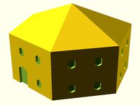
Prusa house
...prusa house
thingiverse
how prusa house could look like...
thingiverse
free

Prusa Mk2 "Fake Prusa" LCD cover by anraf1001
...r by anraf1001
thingiverse
version of prusa's lcd cover with "fake prusa" instead of "original prusa"
thingiverse
free
Prusa stabilizator by gutiueugen
...prusa stabilizator by gutiueugen
thingiverse
prusa stabilizator
thingiverse
free
Keychain Prusa by rbarbalho
...keychain prusa by rbarbalho
thingiverse
keychain with text prusa.
V2
3d_export
free
Lamp v2
...lamp v2
3dexport
lamp v2 with solar panel
3d_export
$5

hammerhead v2
...hammerhead v2
3dexport
razer hammerhead v2 headphones, modeled in cinema 4d, render in corona
3d_export
$5
manometer v2
...manometer v2
3dexport
3d_export
$5

potato v2
...potato v2
3dexport
turbosquid
$52

Lifebuoys v2
...squid
royalty free 3d model lifebuoys v2 for download as fbx on turbosquid: 3d models for games, architecture, videos. (1560870)
turbosquid
$2

Mask v2
...turbosquid
royalty free 3d model mask v2 for download as stl on turbosquid: 3d models for games, architecture, videos. (1527741)
turbosquid
free
Flashlight V2
...d
free 3d model flashlight v2 for download as , obj, and fbx on turbosquid: 3d models for games, architecture, videos. (1663559)
turbosquid
$20
Kitchen V2
...ty free 3d model kitchen v2 for download as max, obj, and fbx on turbosquid: 3d models for games, architecture, videos. (1155111)
turbosquid
$20

kengkod64-v2
... free 3d model kengkod64-v2 for download as 3dm, ztl, and stl on turbosquid: 3d models for games, architecture, videos. (1701415)
turbosquid
$19

Chair v2
...yalty free 3d model chair v2 for download as ma, obj, and fbx on turbosquid: 3d models for games, architecture, videos. (1693360)
Axis
3ddd
$1
Мария Axis
...
3ddd
кухня , классическая , axis
модель кухни.
3d_export
$22
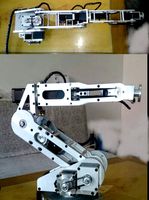
Axis robot 6-axis robotic arm
...ing parts drawings, standard parts purchased parts list, can be produced directly according to the drawings, welcome to download!
3ddd
free

Versatile Axis
...ddd
nexus , плитка
http://bvtileandstone.com/ceramic-porcelain/versatile-axis/
3d_export
$19
robot 2 axis
...robot 2 axis
3dexport
robot 2 axis
turbosquid
$40
Axis R5F
... available on turbo squid, the world's leading provider of digital 3d models for visualization, films, television, and games.
turbosquid
$40
Axis S5F
... available on turbo squid, the world's leading provider of digital 3d models for visualization, films, television, and games.
turbosquid
$30

Axis Athlon
... available on turbo squid, the world's leading provider of digital 3d models for visualization, films, television, and games.
turbosquid
$10

Linear Axis
... available on turbo squid, the world's leading provider of digital 3d models for visualization, films, television, and games.
3d_export
$15

drawing axis
...drawing axis
3dexport
simple rendering of the scene file
3ddd
$1
versatile axis ARC
...versatile axis arc
3ddd
versatile , плитка
versatile axis arc red dot design award
Motor
archibase_planet
free
Motor
...base planet
motor motor engine engine electric motor
motor wagner n250213 - 3d model (*.gsm+*.3ds) for interior 3d visualization.
archibase_planet
free
Motor
...motor
archibase planet
motor motor engine engine
motor n151112 - 3d model (*.gsm+*.3ds) for interior 3d visualization.
archibase_planet
free
Motor
...motor
archibase planet
motor motor engine engine
motor n150615 - 3d model (*.gsm+*.3ds+*.max) for interior 3d visualization.
turbosquid
$15
Motor
...otor
turbosquid
royalty free 3d model motor for download as on turbosquid: 3d models for games, architecture, videos. (1639404)
3d_ocean
$5
Electric motor
...electric motor
3docean
car electric engine industry motor phase train vehicle
an electric motor enjoy!
3d_ocean
$18
Electric Motor
...electric motor
3docean
electric motor engine machine mover parts
3d model electric motor for hoist crane
turbosquid
$29

Motor
... available on turbo squid, the world's leading provider of digital 3d models for visualization, films, television, and games.
turbosquid
$5
Motor
... available on turbo squid, the world's leading provider of digital 3d models for visualization, films, television, and games.
3d_export
$5
electric motor
...electric motor
3dexport
electric motor use for industrial purposes
3d_export
$5
servo motor
...tor
3dexport
it's a simple part of servo motor 0.75kw for used in machines assembly to show specified motor in own project.
Mount
3d_export
free

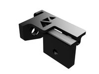
mounting bracket
...mounting plate is the portion of a hinge that attaches to the wood. mounting plates can be used indoors, cabinetry and furniture.
turbosquid
$2

MOUNTING
... available on turbo squid, the world's leading provider of digital 3d models for visualization, films, television, and games.
turbosquid
free

Mounts
... available on turbo squid, the world's leading provider of digital 3d models for visualization, films, television, and games.
turbosquid
free

Mount Fuji
...fuji
turbosquid
free 3d model mount fuji for download as obj on turbosquid: 3d models for games, architecture, videos. (1579977)
3d_export
$5

Headphone mount LR
...headphone mount lr
3dexport
headphone mount l+r
turbosquid
$39

Mount rainier
...quid
royalty free 3d model mount rainier for download as fbx on turbosquid: 3d models for games, architecture, videos. (1492586)
turbosquid
$5

pipe mounting
...quid
royalty free 3d model pipe mounting for download as obj on turbosquid: 3d models for games, architecture, videos. (1293744)
turbosquid
$3

Mounting Tires
...uid
royalty free 3d model mounting tires for download as fbx on turbosquid: 3d models for games, architecture, videos. (1708511)
3d_export
$5

Magnetic GoPro Mount
...pro mount
3dexport
cool magnetic mount for gopro. allows you to mount the camera on flat metal surfaces and get exclusive shots.
turbosquid
$5

Stone Mount
...ty free 3d model stone mount for download as ma, obj, and fbx on turbosquid: 3d models for games, architecture, videos. (1370306)