Thingiverse
Parametric Caged Ball Bearing by rohingosling
by Thingiverse
Last crawled date: 3 years ago
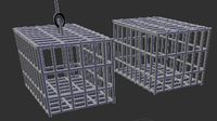
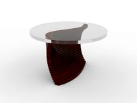
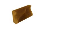
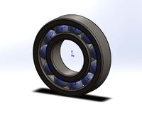
Parametric Caged Ball Bearing
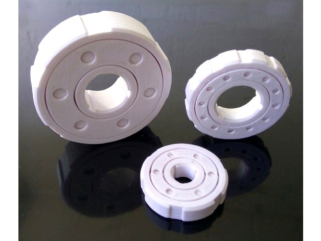
This is a customizable parametric ball bearing, that is designed to be printed in a single step.
Note:
It is extremely challenging to free up the components of this bearing after printing. However, once the components are free, it works great. See the linked video, to get a feel for how various configurations of the bearing perform.
Video:https://youtu.be/iAHtHwBg-FU
Hint
When your hands are bleeding, because you have stabbed your fingers multiple times with the utility knife, and you have friction burns on both hands, ...you are halfway to freeing up the bearing. Maybe the real hint here is that you should wear gloves.
Parameter Overview
All linear, axial and orthogonal dimensions are measured in millimeters. Angles are measured in degrees. And ratios are normalized to the range, [0.0 .. 1.0].
Model Options
Resolution
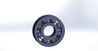
Resolution specifies the tessellation factor of the model. The higher the tessellation factor, the more polygons make up the model. And in turn, the smoother the model. For moving parts like a ball bearing, the smoother the model, the better. So a fairly high resolution of 64 or greater should be selected. I used a resolution of 128 for all the bearings I have printed with this model.
Enable Inner Ring
Include the inner ring if yes. Else, omit the inner ring from the model. This is mostly used for debugging, visual analysis and testing.
Enable Outer Ring
Include the outer ring if yes. Else, omit the outer ring from the model. This is mostly used for debugging, visual analysis and testing.
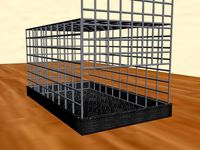
Enable Cage
Include the bearing cage if yes. Else, omit the bearing cage. Due to the friction induced by the cage, most 3D printable ball bearings may spin more freely without a cage. However, even though a cage introduces more friction, load forces are distributed more evenly to the bearing raceway with a cage, leading to an overall better performing bearing. High volume space filling cages like the one in this design, also serve as a spherical support guide for the balls during printing, which improves the spherical quality of each ball.
Enable Balls
Include the bal array if yes. Else, omit the balls. This is used for debugging, visual analysis and testing.
Enable Inner Ring Chamfer
Enable a chamfer on the inner ring if yes. Else, ignore inner ring chamfer parameters.
Enable Outer Ring Chamfer
Enable a chamfer on the outer ring if yes. Else, outer inner ring chamfer parameters.
Enable Inner Ring Knurling
Enable knurling cuts on the inner ring if yes. Else, ignore inner ring knurling parameters.
Enable Outer Ring Knurling
Enable knurling cuts on the outer ring if yes. Else, ignore outer ring knurling parameters.
Enable Bottom Cage Access Ports
Enable access ports on the side of the cage, that is facing the build plate during printing. Presuming that the bearings are oriented flat on the build plate, then we can call this the bottom face of the cage. Access ports serve a dual purpose. 1.To gain access to the support material used to for the balls, if support material is used. 2. To gain access to the balls themselves after printing, so that they can be manipulated in order to free them from the cage and the rings.
Enable Top Cage Access Ports
Enable access ports on the side of the cage, that is facing away from the build plate during printing. Presuming that the bearings are oriented flat on the build plate, then we can call this the top face of the cage. It is a good idea to include access ports on both sides of the cage, to maximize access to the balls for post printing manipulation, as well as to ensure balanced rolling in the cage, once the balls have been freed.
Ring and Cage Parameters:
Bore
This is the inner diameter of the inner ring. It is a good idea to make this value slightly larger than the diameter of whatever shaft is intended to pass through the inner ring, by about 0.1mm to 0.5mm. Presuming, that the target shaft diameter can't be adjusted itself. If need be, the Model Options above may be used to print only the inner ring as a test part, that may then be be fitted to the target shaft, in order to iteratively evaluate physical assembly characteristics, without having to print the entire bearing assembly each time.
Outer Diameter
This is the outer diameter of the outer ring. It is a good idea to make this value slightly smaller than the diameter of whatever bracket assembly the bearing is intended to fit into, by about 0.1mm to 0.5mm. Presuming, that the target assembly dimensions can't be adjusted themselves. If need be, the Model Options above may be used to print only the outer ring as a test part, that may then be be fitted to the target assembly, in order to iteratively evaluate physical assembly characteristics, without having to print the entire bearing assembly each time.
Shoulder Height
This is the raised boundary edge of the bearing raceway. In general, lower values are prefered. The minimum shoulder height required to give the balls a secure raceway to roll along, should suffice. For bearings whose outer diameters are less than 60mm, a 1mm to 1.5mm shoulder height is usually enough.
Radial Gauge
This is the thickness of the rings, as measured from the deepest point of the ring raceway, to the inner or outer diameter of the inner and outer rings respectively.
Axial Gauge
This is the thickness of the ring and cage walls.
Cage Access Port Diameter
This is the diameter of the cage access ports. In general, the larger the better, especially if support material is going to be used to support the balls above the build plate during printing.
Mechanical Properties:
Ball Count
The number of balls.
Ball Ring Clearance
The clearance between each ball and the rings. The radius of the balls is reduced by this clearance amount. In general, fairly low clearance values should be used between the balls and the rings, in order to promote grip between the balls and the ring raceways. For most applications, clearance in the range of 0.1mm to 0.3mm, works well for clearance between the balls and the rings.
Ball Cage Clearance
The clearance between each ball, and its cage cavity surface. The radius of the cage cavity surfaces, are increased from the radius of each ball, by this clearance value. Larger clearance values are suitable for the clearance between the balls and the cage, in order to reduce friction. It is a good idea to set the clearance between the balls and the cage, to a larger clearance value, than the clearance between the balls and the rings, in order to promote frictional contact between the balls and the rings, rather than unnecessary contact between than balls and the cage. In general, a value of two to three times the clearance between the balls and the rings, works well for the clearance between the balls and the cage. Most of the bearings that I print using this model, are configured with a ball to ring clearance of 0.1mm, and a ball to cage clearance of 0.3mm, using a 0.3mm nozzle, and a print resolution of x=0.3mm, y=0.3mm, and z=0.15mm.
Feature Parameters:
Inner Chamfer Size
The radial size of the inner ring chamfer.
Outer Chamfer Size
The radial size of the outer ring chamfer.
Inner Knurling Count
The number of equally spaced knurling cuts made into the inner ring.
Inner Knurling Depth
The depth of the inner knurling cuts.
Inner Knurling Cut Ratio
The proportion of the knurling arc, that is cut into the ring. The higher the ratio, the more material is cut from the ring.
Outer Knurling Count
The number of equally spaced knurling cuts made into the outer ring.
Outer Knurling Depth
The depth of the outer knurling cuts.
Outer Knurling Cut Ratio
The proportion of the knurling arc, that is cut into the ring. The higher the ratio, the more material is cut from the ring.
Color Settings:
Color settings are used for debugging and analysis.
Enable Multiple Colors
Render each class of component in using different colors if yes. Else, render all components in the model using one color.
Default Color
The color to use if "Enable Multiple Colors" is set to No. If "Enable Multiple Colors" is set to Yes, then "Default Color" is ignored.
Inner Ring Color
The color to render the inner ring, when "Enable Multiple Colors" is set to Yes.
Outer Ring Color
The color to render the outer ring, when "Enable Multiple Colors" is set to Yes.
Ball Color
The color to render the ball array, when "Enable Multiple Colors" is set to Yes.
Cage Color
The color to render the bearing cage, when "Enable Multiple Colors" is set to Yes.
This is a customizable parametric ball bearing, that is designed to be printed in a single step.
Note:
It is extremely challenging to free up the components of this bearing after printing. However, once the components are free, it works great. See the linked video, to get a feel for how various configurations of the bearing perform.
Video:https://youtu.be/iAHtHwBg-FU
Hint
When your hands are bleeding, because you have stabbed your fingers multiple times with the utility knife, and you have friction burns on both hands, ...you are halfway to freeing up the bearing. Maybe the real hint here is that you should wear gloves.
Parameter Overview
All linear, axial and orthogonal dimensions are measured in millimeters. Angles are measured in degrees. And ratios are normalized to the range, [0.0 .. 1.0].
Model Options
Resolution
Resolution specifies the tessellation factor of the model. The higher the tessellation factor, the more polygons make up the model. And in turn, the smoother the model. For moving parts like a ball bearing, the smoother the model, the better. So a fairly high resolution of 64 or greater should be selected. I used a resolution of 128 for all the bearings I have printed with this model.
Enable Inner Ring
Include the inner ring if yes. Else, omit the inner ring from the model. This is mostly used for debugging, visual analysis and testing.
Enable Outer Ring
Include the outer ring if yes. Else, omit the outer ring from the model. This is mostly used for debugging, visual analysis and testing.
Enable Cage
Include the bearing cage if yes. Else, omit the bearing cage. Due to the friction induced by the cage, most 3D printable ball bearings may spin more freely without a cage. However, even though a cage introduces more friction, load forces are distributed more evenly to the bearing raceway with a cage, leading to an overall better performing bearing. High volume space filling cages like the one in this design, also serve as a spherical support guide for the balls during printing, which improves the spherical quality of each ball.
Enable Balls
Include the bal array if yes. Else, omit the balls. This is used for debugging, visual analysis and testing.
Enable Inner Ring Chamfer
Enable a chamfer on the inner ring if yes. Else, ignore inner ring chamfer parameters.
Enable Outer Ring Chamfer
Enable a chamfer on the outer ring if yes. Else, outer inner ring chamfer parameters.
Enable Inner Ring Knurling
Enable knurling cuts on the inner ring if yes. Else, ignore inner ring knurling parameters.
Enable Outer Ring Knurling
Enable knurling cuts on the outer ring if yes. Else, ignore outer ring knurling parameters.
Enable Bottom Cage Access Ports
Enable access ports on the side of the cage, that is facing the build plate during printing. Presuming that the bearings are oriented flat on the build plate, then we can call this the bottom face of the cage. Access ports serve a dual purpose. 1.To gain access to the support material used to for the balls, if support material is used. 2. To gain access to the balls themselves after printing, so that they can be manipulated in order to free them from the cage and the rings.
Enable Top Cage Access Ports
Enable access ports on the side of the cage, that is facing away from the build plate during printing. Presuming that the bearings are oriented flat on the build plate, then we can call this the top face of the cage. It is a good idea to include access ports on both sides of the cage, to maximize access to the balls for post printing manipulation, as well as to ensure balanced rolling in the cage, once the balls have been freed.
Ring and Cage Parameters:
Bore
This is the inner diameter of the inner ring. It is a good idea to make this value slightly larger than the diameter of whatever shaft is intended to pass through the inner ring, by about 0.1mm to 0.5mm. Presuming, that the target shaft diameter can't be adjusted itself. If need be, the Model Options above may be used to print only the inner ring as a test part, that may then be be fitted to the target shaft, in order to iteratively evaluate physical assembly characteristics, without having to print the entire bearing assembly each time.
Outer Diameter
This is the outer diameter of the outer ring. It is a good idea to make this value slightly smaller than the diameter of whatever bracket assembly the bearing is intended to fit into, by about 0.1mm to 0.5mm. Presuming, that the target assembly dimensions can't be adjusted themselves. If need be, the Model Options above may be used to print only the outer ring as a test part, that may then be be fitted to the target assembly, in order to iteratively evaluate physical assembly characteristics, without having to print the entire bearing assembly each time.
Shoulder Height
This is the raised boundary edge of the bearing raceway. In general, lower values are prefered. The minimum shoulder height required to give the balls a secure raceway to roll along, should suffice. For bearings whose outer diameters are less than 60mm, a 1mm to 1.5mm shoulder height is usually enough.
Radial Gauge
This is the thickness of the rings, as measured from the deepest point of the ring raceway, to the inner or outer diameter of the inner and outer rings respectively.
Axial Gauge
This is the thickness of the ring and cage walls.
Cage Access Port Diameter
This is the diameter of the cage access ports. In general, the larger the better, especially if support material is going to be used to support the balls above the build plate during printing.
Mechanical Properties:
Ball Count
The number of balls.
Ball Ring Clearance
The clearance between each ball and the rings. The radius of the balls is reduced by this clearance amount. In general, fairly low clearance values should be used between the balls and the rings, in order to promote grip between the balls and the ring raceways. For most applications, clearance in the range of 0.1mm to 0.3mm, works well for clearance between the balls and the rings.
Ball Cage Clearance
The clearance between each ball, and its cage cavity surface. The radius of the cage cavity surfaces, are increased from the radius of each ball, by this clearance value. Larger clearance values are suitable for the clearance between the balls and the cage, in order to reduce friction. It is a good idea to set the clearance between the balls and the cage, to a larger clearance value, than the clearance between the balls and the rings, in order to promote frictional contact between the balls and the rings, rather than unnecessary contact between than balls and the cage. In general, a value of two to three times the clearance between the balls and the rings, works well for the clearance between the balls and the cage. Most of the bearings that I print using this model, are configured with a ball to ring clearance of 0.1mm, and a ball to cage clearance of 0.3mm, using a 0.3mm nozzle, and a print resolution of x=0.3mm, y=0.3mm, and z=0.15mm.
Feature Parameters:
Inner Chamfer Size
The radial size of the inner ring chamfer.
Outer Chamfer Size
The radial size of the outer ring chamfer.
Inner Knurling Count
The number of equally spaced knurling cuts made into the inner ring.
Inner Knurling Depth
The depth of the inner knurling cuts.
Inner Knurling Cut Ratio
The proportion of the knurling arc, that is cut into the ring. The higher the ratio, the more material is cut from the ring.
Outer Knurling Count
The number of equally spaced knurling cuts made into the outer ring.
Outer Knurling Depth
The depth of the outer knurling cuts.
Outer Knurling Cut Ratio
The proportion of the knurling arc, that is cut into the ring. The higher the ratio, the more material is cut from the ring.
Color Settings:
Color settings are used for debugging and analysis.
Enable Multiple Colors
Render each class of component in using different colors if yes. Else, render all components in the model using one color.
Default Color
The color to use if "Enable Multiple Colors" is set to No. If "Enable Multiple Colors" is set to Yes, then "Default Color" is ignored.
Inner Ring Color
The color to render the inner ring, when "Enable Multiple Colors" is set to Yes.
Outer Ring Color
The color to render the outer ring, when "Enable Multiple Colors" is set to Yes.
Ball Color
The color to render the ball array, when "Enable Multiple Colors" is set to Yes.
Cage Color
The color to render the bearing cage, when "Enable Multiple Colors" is set to Yes.
Similar models
grabcad
free

Ball Bearing
... cage.
a ball bearing is a type of rolling-element bearing that uses balls to maintain the separation between the bearing races.
grabcad
free

ball bearing
...ball bearing
grabcad
ball bearing
ball
cage
inner ring
outer ring
grabcad
free

Ball Bearing
...ball bearing
grabcad
ball bearing
ball
cage
outer ring
inner ring
grabcad
free

Ball bearing
...ball bearing
grabcad
ball bearing..
with inner ring, cage, outer ring and rivets sldprt files
grabcad
free

BALL BEARING DRAW BY USING CATIA SOFTWARE
...are
grabcad
ball bearing sub parts and assembly of ball bearing
cage
inner ring
outer ring
this is draw by using catia software
cg_trader
$2
Ball Bearing
...ball bearing
cg trader
this model is of a ball bearing consiting of four parts, ball, inner ring, outer ring and cage
grabcad
free

Ball Bearing
...aring
grabcad
it is an assembly file of a ball bearing made up of ball, cage, inner ring and outer ring etc, in solidworks 2016.
grabcad
free

Ball Bearing
...ball bearing
grabcad
parts:
1. ball
2. cage
3. outer ring
4. inner ring
grabcad
free

Ball Bearing
...ball bearing
grabcad
this is a ball bearing assembly, which includes following parts
outer and inner ring, cage, balls, rivets
thingiverse
free
More Bearings - Filament by chuck787
...nner and outer race to remove volunteer abs. the bearings are from amazon about $4 for 100. the design uses 15 ball bearings.
Rohingosling
thingiverse
free
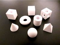
Test Block by rohingosling
...test block by rohingosling
thingiverse
general purpose parametric test and calibration part.
use the customizer to configure.
thingiverse
free
Heat Insert Test Panel by rohingosling
...ing
thingiverse
heat insert test panel. use this to test various heat insert hole sizes, or to practice installing heat inserts.
thingiverse
free
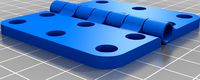
Experimental Parametric Hinge by rohingosling
...ove. the original is less likely to have bugs, and is also maintained and updated more frequently than this experimental version.
thingiverse
free
Parametric Hinge by rohingosling
...rence of the fastener head, to the edge of the leaf.
values between 3mm and 5mm are recommended for small to medium gauge hinges.
thingiverse
free
Toy Dog Crate by CKetner
...baby pound puppies. credit for the hinges goes to rohingosling https://www.thingiverse.com/thing:2187167. and credit for the snap shut locks goes...
thingiverse
free
Parametric Butt Hinge by z3d
...by z3d thingiverse the parametric butt hinge design from @rohingosling is awesome. original here's an online version that doesn't...
thingiverse
free
t-slot hinge by spacesaver
...the door of my eustathios v2. so i used rohingosling#39;s hinge generator and made the center of rotation as...
thingiverse
free
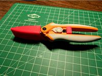
Fiskars Easy Action Micro-tip Scissors Guard by knowledgecravings
...will come up with a better idea. thanks to rohingosling for the hinge design https://www.thingiverse.com/thing:2187167, as i don't yet...
thingiverse
free
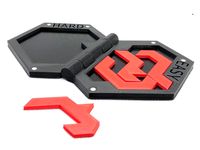
Puzzle of Evil
...joe larson's 3d printed puzzle of evil, combined with rohingosling#39;s parametric...
Caged
3d_export
$5
cage
...cage
3dexport
cage
archibase_planet
free
Cage
...cage
archibase planet
cage bird cage birdcage
cage 2 - 3d model (*.gsm+*.3ds) for interior 3d visualization.
archibase_planet
free
Cage
...cage
archibase planet
cage bird cage birdcage
cage 1 - 3d model (*.gsm+*.3ds) for interior 3d visualization.
archibase_planet
free
Cage
...cage
archibase planet
cage bird cage birdcage
cage 3 - 3d model (*.gsm+*.3ds) for interior 3d visualization.
archibase_planet
free
Cage
...cage
archibase planet
bird's cage cage
cage n020909 - 3d model (*.gsm+*.3ds) for interior 3d visualization.
archibase_planet
free
Cage
...cage
archibase planet
cage
cage monte- 3d model for interior 3d visualization.
3d_export
$7
cage
...cage
3dexport
3d cage model
archibase_planet
free
Cage
...cage
archibase planet
cage
cage n270211 - 3d model (*.gsm+*.3ds) for interior 3d visualization.
turbosquid
$5
Cage
...ge
turbosquid
royalty free 3d model cage for download as dwg on turbosquid: 3d models for games, architecture, videos. (1224275)
turbosquid
$4
cage
...squid
royalty free 3d model cage for download as max and fbx on turbosquid: 3d models for games, architecture, videos. (1368360)
Parametric
turbosquid
$25
Parametric
...oyalty free 3d model parametric for download as blend and stl on turbosquid: 3d models for games, architecture, videos. (1683196)
3ddd
$1
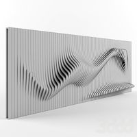
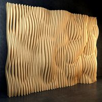
Parametric Wall
...parametric wall
3ddd
панель
parametric wall with shelf
3d_export
$5
parametric table
...parametric table
3dexport
parametric table model created on rhinoceros 6. this 3d model includes: .gh, .3dm files
turbosquid
$2
parametrical chandelier
...lty free 3d model parametrical chandelier for download as dxf on turbosquid: 3d models for games, architecture, videos. (1257635)
turbosquid
$2
Parametric Seat
...id
royalty free 3d model parametric seat for download as max on turbosquid: 3d models for games, architecture, videos. (1691557)
turbosquid
$2
Parametric Wall
...id
royalty free 3d model parametric wall for download as max on turbosquid: 3d models for games, architecture, videos. (1690373)
turbosquid
$1
Parametric Wall
...id
royalty free 3d model parametric wall for download as max on turbosquid: 3d models for games, architecture, videos. (1691303)
turbosquid
$1
Parametric Wall
...id
royalty free 3d model parametric wall for download as max on turbosquid: 3d models for games, architecture, videos. (1691148)
turbosquid
$19
Parametric Bench
...ty free 3d model parametric bench for download as max and max on turbosquid: 3d models for games, architecture, videos. (1713396)
turbosquid
free
Parametric wall
...ee 3d model parametric wall for download as max, obj, and fbx on turbosquid: 3d models for games, architecture, videos. (1356869)
Bearing
3d_export
$6
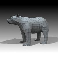
Bear
...bear
3dexport
bear
3d_export
$5
bearing
...bearing
3dexport
bearing
3d_export
$12
bear
...bear
3dexport
bear for 3d printing toy
3d_ocean
$9
Bearing
...ne ball ballbea bearing bearings engine hard industrial machine mechanic metal part piece plastic ring screw sphere steel
bearing
archibase_planet
free
Bear
...bear
archibase planet
statuette bear picturesque element
bear - 3d model (*.gsm+*.3ds) for interior 3d visualization.
3d_export
$5
bear
...bear
3dexport
bear have a stl.,3dm files
archibase_planet
free
Bear
...bear
archibase planet
bear animals omnivorous animal
bear angry n250907- 3d model (*.gsm+*.3ds) for interior 3d visualization.
archibase_planet
free
Bear
...bear
archibase planet
bear animals omnivorous animal
bear easy n250907 - 3d model (*.gsm+*.3ds) for interior 3d visualization.
3ddd
$1

Teddy bear
...teddy bear
3ddd
teddy bear , медведь
teddy bear :)
3d_ocean
$12
Bear
... formats. created with 3d max 9.0. this file is very useful for learning & rigging. it can be used for any professional work.
Ball
turbosquid
$5
Ball on a Ball
...uid
royalty free 3d model ball on a ball for download as obj on turbosquid: 3d models for games, architecture, videos. (1484719)
archibase_planet
free
Ball
...ball
archibase planet
ball golf ball
ball - 3d model (*.gsm+*.3ds) for 3d visualization.
3d_export
$5

ball
...ball
3dexport
ball
archibase_planet
free

Ball
...ball
archibase planet
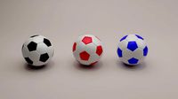
ball football soccer ball
ball n100714 - 3d model (*.gsm+*.3ds+*.max) for exterior 3d visualization.
3d_export
$5
ball
...ball
3dexport
soccer ball
archibase_planet
free
Ball
...ball
archibase planet
ball football
ball n100914 - 3d model (*.gsm+*.3ds+*.max) for 3d visualization.
3d_ocean
$5
Snooker Balls
... set balls snooker snooker balls white ball yellow ball
set snooker balls format include : .c4d .3ds .obj build in cinema 4d r13
3d_export
free

ball
...ball
3dexport
this is 3d model ball's
3d_ocean
$2
Soccer Ball
...soccer ball
3docean
ball red and yellow ball red ball soccer ball
a gorgeous red and yellow seamless soccer ball
3d_ocean
$5

Billard Balls
...low poly billiard balls. numbering from 1 to 15 plus the cue ball. each of the balls excluding the cue ball has a 4k texture map.