Thingiverse
Panzertriebwagen nr 16 in H0 (1/87) scale (Märklin) by dasbert33
by Thingiverse
Last crawled date: 3 years ago
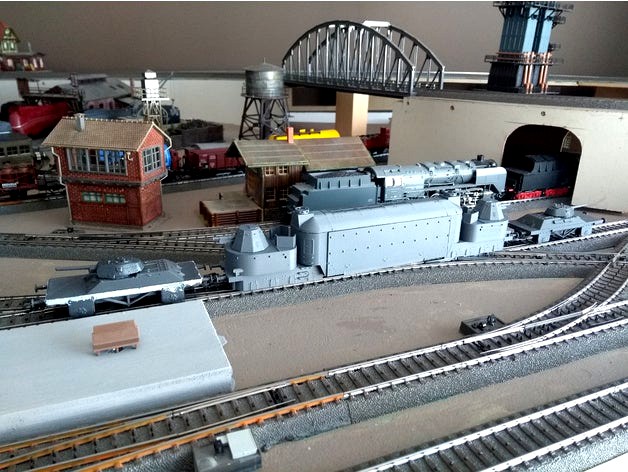
Panzertriebwagen nr 16 in H0 (1/87) scale
For matching panzerjagerwagen, as in the picture go here: https://www.thingiverse.com/thing:2771957
They were used on both ends of the railcar for additional firepower.
My goal was to make a fully functional model of Panzertriebwagen nr 16, for use on my Marklin MRR. It has NEM coupler pockets and white/red light changeover with LEDs.
It is based on the good old metal BR81 chassis. This was the closest (& cheapest) resemblance of the original engine under the armored dome, the WR550D.
Some compromises have been made for my MRR, most noticable near the lights. They are not freestanding but integrated in the turret chassis. The coupler rods have been made 1mm longer to negotiate curves better.
I recommend R2 (420mm radius) curves only, I think some steps are in the way for proper R1 operation.
Most parts have been printed in PLA in 0.1 Z-res. Buffers, NEM coupler holder and lightguides have been printed in ABS, the latter in transparent ABS. For the coupler this is because of better elasticity (better centring), and for the buffers for better rigidity.
I also recommend to glue the buffers.
Everything was designed in FreeCad.
Parts to be printed, amount requirements are between brackets:
(1x) balk1_1mm.stl: coupler rod between center body and turret part. Mount on the engine side of the BR81 chassis.
(1x) balk2_1mm.stl: coupler rod between center body and turret part. Mount on the electronics side of the BR81 chassis.
(2x) blob.stl: upper part of the turret chassis
(4x) buffer.stl: buffers for the chassis, best printed in ABS and glued to chassis. Use 1mm drill to clear the holes
(2x) chassis.stl: lower part of turret chassis. (print upside down). It has provisions for cable guiding. Use thin cables (0.5mm).
(1x) dakaf.stl: roof of the center armored dome
(2x) dakdeksel.stl: covers for on the roof, hiding some srews
(4x) draaistel.stl: bogies for under the turret parts (print upside down)
(1x) klok.stl: main body of armored dome (print upside down). It has mounting space for a PCB on both ends that can host a connector
(2x) koppeling.stl: NEM coupler pocket, compatible to original marklin Relex couplers, should be usable on other models as well. Best printed in ABS
(2x) lichtgeleider_L.stl: left side light conductor. To be printed in a transparent material if lighting is to be used. I used transparent ABS.
(2x) lichtgeleider_R.stl: right side light conductor. To be printed in a transparent material if lighting is to be used. I used transparent ABS.
(2x) pcbhouder.stl: holder to be able to mount a pcb with LEDs. See lichtpcb.stl for shape info. Can be made out of standard 100mil pitch prototype boards with
(2x) toren.stl: the turrets for both ends
Reference parts, not to be printed:
br81_chassis.stl: how the br81 chassis should more or less look like after cutting away the buffers. I used this to design the body around.
lichtpcb.stl: how the PCB with the LEDs should look like (10x2 holes 2.54mm pitch print)
Other material required:
NEM362 compatible coupler (2x). I used Marklins.
wheelsets (8x): Artitec 20.340.01 or compatible. You can also recycle wheelsets from Marklin Hobby car wheels (10.4mm diameter, 24.4mm length, pointy ends)
2.6mmx8 self tapping screws with collar (4x) (2.6mmx6 will also work). Used for mounting the roof on the body and for holding the NEM-coupler.
2mmx6 self tapping screws with collar (6x). Used for mounting the bogies and the coupler bars betweens center and outer pieces.
1.6mmx5 self tapping screws (24x). Used for mounting the electronics, lighting, turret body on turret chassis.
0.5mm diameter steel wire. To create the different handrails (8 pieces) by cutting to length and bending.
(Old) Marklin BR81 locomotive. #3031, #3032, #30321, #30322. Only the older model with the full rods (and old metal coupler system) will work.
The newer one has a different coupling system and is not compatible with this design.
M2.5 screws for mounting the body on the BR81 chassis, where the original coupler rod steering was mounted.
Electronics:
0603 SMD LEDs red (4x)
0603 SMD LEDs white (4x)
1206 1K SMD resistor (4x)
1.6mm thick, 2.54mm (100mil) pitch PCB prototype board, to be cut into shape to fit
100mil pitch headers & receptacles, if you want the turrets parts to be able to easily disconnect. On the main body there are mounting holes for PCBs to hold these.
cabling for the lights, 0.5mm in various colors
Usefull tools:
Drills of sizes: 0.5mm, 1mm, 1.2mm, 1.8mm, 2.7mm to clean the holes for the screws etc.
Modifying the BR81 for Pz16:
The chassis is to long and the buffers and cilinders have to be removed. I used an oscillating multitool, but you can also use a Dremel.
Make sure to remove all loose parts before starting the surgery: motor, electronics, slider, coupler rods.
The most important part is that you keep the coupler mounting intact as we will reuse it for the couplers bars.
Refer to the reference part 'br81_chassis' to see how it should look like when finished. Ideally the body fits snug over the chassis you have cut.
Also, the cilindric part with threads on the 3rd axle should be shortened to be able to fit the body. I recommend cutting off only the threaded part.
Have fun with this design.
Similar models
thingiverse
free

Panzerjagerwagen T-34 in H0 scale by dasbert33
...n are printed in abs pro. one is a print of the combination, the other is using the seperate files. i filled the gaps with putty.
thingiverse
free

Budget and Better than DJI! 3D Printed/ Laser Cut 10" Drone
...he nuts in place.
electronics i used:
4x t-motor 2216 11 900kv motors
mamba f405 stack
bn880 gps
bmp280 barometer
4000mah 3s lipo
thingiverse
free

H0 scale wagon chassis compatible with Hobby series by dasbert33
...some glue to attach the buffers
i will likely produce more compatible top parts in the future, so keep an eye on my account ;-).
thingiverse
free

parts for robotic dog by therobotcarlson
...ne
1x spine connector
2x front
4x socket
4x twist
4x femur
4x femur_back
4x thight_socket
4x feet
2x rod
3x rod_2
1x head
1x tail
thingiverse
free

Basic Drive Chassis by rafikiand3601
... to use, but due to the single stage gearbox, is very high speed.
message me if you have any questions about this project,
enjoy!
thingiverse
free

Duplo Steam Locomotive by svenny
...rator
4x small wheel
2x (4x) big wheel
2x big wheel with axis (still under construction)
2x piston rod (still under construction)
thingiverse
free

LUMITREE - Branch Adaptable Lamp by rapzz
...0mm screw
2x m5 30mm screw
2x m5 lock nut
this project is totally adaptable, so you can make your lamp in the way you want it to.
thingiverse
free

Baseplate for spindle clamp (52/55mm), CNC3018/CNC3018 Pro
...sher
4x m6 spring ring
optional:
4x m2x14mm (allen) screw
2x micro switch (print)
1x anti backlash nut
2x 5x56mm rod
2x linelaser
thingiverse
free

CNC laser cutter by TheMadScientist
... x 1000mm x 5mm plywood
2x 4mm to 8mm couplers
6x 8mm bearings
4x 8mm tee nuts
wood glue
patience
one day, i will make this....
cults
free

John Deere Tractor and Trailer
...2x tear rear 2
part list trailer:
1x trailer body
4x trailer rim
4x trailer tire 1
4x trailer tire 2
...and have fun! :-)
Dasbert33
thingiverse
free

Sand pile for Faller #120146 sand house by dasbert33
... dasbert33
thingiverse
sand pile for faller sand house, as no sand pile was supplied with the model (only a bag of actual sand).
thingiverse
free

Track bumpers HO scale for Marklin/Trix Ctrack by dasbert33
...n/trix crails.
please post makes in case you decide to print this. it works ok for me with both pla and petg filament.
have fun!
thingiverse
free

HO scale loading ramp for Marklin/Trix C track by dasbert33
...on variants.
height aligned with marklin 4867 (or similar) heavy duty cars.
if you print this, please post a make.
have fun.
bert
thingiverse
free

Marklin H0 Hobby train car Lego conversion by dasbert33
...s whose upper half had broken off.
this makes a nice 2-axle car that fits nicely together with the 4-axle car that marklin sells.
thingiverse
free

H0 platform stairs, compatible with Viessmann/Kibri Kienbach platform series by dasbert33
...t can ofc be cut to make shallower if required.
i printed this in 0.1mm resolution with supports to support the 'collar'.
thingiverse
free
Panzerjagerwagen T-34 in H0 scale by dasbert33
...n are printed in abs pro. one is a print of the combination, the other is using the seperate files. i filled the gaps with putty.
thingiverse
free

Wheels set for turnigy 4WD rally RC car, 9mm hex by dasbert33
...ody (colt 1/10 mini cooper body from rcmart.com). there is also a comparison picture of the custom wheels with the original ones.
thingiverse
free

Hopper car body, for Marklin hobby range car chassis by dasbert33
...only the grey colored part is included here. i added an assembled 3d model for use in thingyviewer, this one is not for printing.
thingiverse
free

Shelby Cobra static model by JPza
...4wd rally rc car, 9mm hex (https://www.thingiverse.com/thing:2809958) by dasbert33 (https://www.thingiverse.com/dasbert33about) car seat (https://www.thingiverse.com/thing:2749777) by lauden...
thingiverse
free
H0 scale wagon chassis compatible with Hobby series by dasbert33
...some glue to attach the buffers
i will likely produce more compatible top parts in the future, so keep an eye on my account ;-).
Märklin
thingiverse
free

Märklin Kupplungsadapter by Scheffkoch
...tte kauft den adapter im märklin-shop und unterstützt damit märklin und die märklin-einzelhändler... außer das ist unpraktikabel!
thingiverse
free

Guardrail märklin sprint by VolkerHochholzer
...guardrail märklin sprint by volkerhochholzer
thingiverse
2.8m guardrail for märklin sprint.
thingiverse
free

Märklin 4500 LEGO-adapter by thedany
...pter by thedany
thingiverse
a lego - compatible plate for the classic märklin 4500 - chassis. it is just clipped to the chassis.
thingiverse
free

Märklin Alpha Cover with vents by matthiaswiesmann
...lin in the 80s.
the vents come from the vents / grills / louvres for scratchbuilding/kitbashing 1/60 scale robot models project.
thingiverse
free

Caps for Märklin street lamps 7282 by ccs66
...in 1972 often the plastic-caps are missing.
they are printed in regular, white pla. original märklin part number: 41453 / 414530
thingiverse
free

Märklin 3000 decoder support by matthiaswiesmann
... inside a märklin 3000 h0 locomotive. it is designed to be screwed in where the inverter is, with a hole for cables at the front.
thingiverse
free

Gleisbox Halter Märklin 601132 60116 / Track box halter Märklin 601132 60116 by jogiarea
...or screwing on the märklin track box
you need two of the brackets
this is then fastened with 2 countersunk screws diameter 3 each
thingiverse
free

Transportbox Spur Z, Miniclub, Märklin by Stagi741
...n miniclub) eisenbahnen oder waggons.
maßstab 1:220
small transportbox for z line trains or wagons (märklin miniclub)
scale 1:220
thingiverse
free

Wagen Entkoppler für Märklin H0 Modelleisenbahn by Thomsson
...wagen entkoppler für märklin h0 modelleisenbahn by thomsson
thingiverse
wagen entkoppler für märklin h0 modelleisenbahn
thingiverse
free

Schranke Märklin H0 Railway Barrier by exrcvhjblnkz
...ay barrier by exrcvhjblnkz
thingiverse
simple design for a lost märklin railway barrier.
has a 3.4mm opening and is ~9.5cm long.
H0
thingiverse
free

Tranvia H0, scale h0 by hora80
...tranvia h0, scale h0 by hora80
thingiverse
tranvia escala 1:87 / h0
thingiverse
free

H0 Santa by ClasseMan
...h0 santa by classeman
thingiverse
santa with christmas gifts in h0 scale.
santa is based on a h0 worker made by timo77.
thingiverse
free

H0 Fence by wlaros
...h0 fence by wlaros
thingiverse
simple fence for h0
thingiverse
free

h0 bridge by 3dcyberuser
...h0 bridge by 3dcyberuser
thingiverse
bridge for h0 scale
thingiverse
free

H0 skala grind by InnlandsModeller
...h0 skala grind by innlandsmodeller
thingiverse
h0 skala grind.
thingiverse
free

Metallzaun für H0 by MV1985
...metallzaun für h0 by mv1985
thingiverse
metallzaun für h0
thingiverse
free

H0 drainage culvert by droz1
...h0 drainage culvert by droz1
thingiverse
h0 water evacuation nozzle drainage culvert - buses d’évacuation des eaux pluviales h0
thingiverse
free

Fence on H0 scale by vqsoft
...fence on h0 scale by vqsoft
thingiverse
simply fence on h0 scale.
thingiverse
free

H0 Kupplung / coupler
... coupler
thingiverse
coupler for h0 waggons like https://www.thingiverse.com/thing:2771793 with better pliability. hole is 2.5mm
thingiverse
free

Straight track H0
...straight track h0
thingiverse
track underlay, for h0 rail and piko rails. flexible track 940 mm item no .: 55209
87
turbosquid
$140

Tatra 87
...urbosquid
royalty free 3d model tatra 87 for download as max on turbosquid: 3d models for games, architecture, videos. (1328810)
turbosquid
$15

Chair 87
...alty free 3d model chair 87 for download as max, obj, and fbx on turbosquid: 3d models for games, architecture, videos. (1497544)
turbosquid
$15

Curtain 87
...ty free 3d model curtain 87 for download as max, obj, and fbx on turbosquid: 3d models for games, architecture, videos. (1462501)
turbosquid
$8

Table 87
...alty free 3d model table 87 for download as max, obj, and fbx on turbosquid: 3d models for games, architecture, videos. (1503920)
turbosquid
$8

Lamp 87
...yalty free 3d model lamp 87 for download as max, obj, and fbx on turbosquid: 3d models for games, architecture, videos. (1500815)
turbosquid
$6

Bedcloth 87
...y free 3d model bedcloth 87 for download as max, fbx, and obj on turbosquid: 3d models for games, architecture, videos. (1531165)
turbosquid
$20

BAth 87
... free 3d model bath 87 for download as max, dxf, fbx, and dwg on turbosquid: 3d models for games, architecture, videos. (1277154)
turbosquid
$29

Landscape 87
... available on turbo squid, the world's leading provider of digital 3d models for visualization, films, television, and games.
turbosquid
$25

Ring 87
... available on turbo squid, the world's leading provider of digital 3d models for visualization, films, television, and games.
turbosquid
$23

Building 87
... available on turbo squid, the world's leading provider of digital 3d models for visualization, films, television, and games.
Nr
turbosquid
$100

Nr locomotive
...free 3d model nr locomotive for download as max, obj, and fbx on turbosquid: 3d models for games, architecture, videos. (1375585)
turbosquid
$100

NR locomotive
...free 3d model nr locomotive for download as max, obj, and fbx on turbosquid: 3d models for games, architecture, videos. (1374907)
turbosquid
$39

NRS-2
...ty free 3d model nrs-2 for download as 3ds, max, obj, and fbx on turbosquid: 3d models for games, architecture, videos. (1157013)
3ddd
$1

giorgiocasa Art. 451 NR
...giorgiocasa art. 451 nr
3ddd
giorgiocasa , журнальный
giorgiocasa art. 451 nr
turbosquid
$100

nr 29 locomotive
...e 3d model nr 29 locomotive for download as max, obj, and fbx on turbosquid: 3d models for games, architecture, videos. (1375224)
turbosquid
$25

Matchbox Nr. 54
... available on turbo squid, the world's leading provider of digital 3d models for visualization, films, television, and games.
turbosquid
$25

Matchbox Nr. 7B
... available on turbo squid, the world's leading provider of digital 3d models for visualization, films, television, and games.
turbosquid
$20

beer bottle nr
... available on turbo squid, the world's leading provider of digital 3d models for visualization, films, television, and games.
turbosquid
$19

SKYSCRAPER NR.25
... available on turbo squid, the world's leading provider of digital 3d models for visualization, films, television, and games.
turbosquid
$15

SKYSCRAPER NR.13
... available on turbo squid, the world's leading provider of digital 3d models for visualization, films, television, and games.
16
3ddd
$1

Bed 16
...bed 16
3ddd
постельное белье
bed 16.hope you like it.thanks you very much
design_connected
$4

Bolla 16
...bolla 16
designconnected
gervasoni bolla 16 coffee tables computer generated 3d model. designed by michael sodeau.
3d_export
$6

tap-16
...tap-16
3dexport
3d_export
$6

set-16
...set-16
3dexport
3ddd
$1

16 Mobilier ALIXE
... уличная , мебель
производитель: 16 mobilier
модель: alixe
3ddd
$1

Curtains 16
...curtains 16
3ddd
ламбрикен
curtains 16
polys: 350077
other models:http://3ddd.ru/users/brast/models
turbosquid
$199

F-16
...16
turbosquid
royalty free 3d model f-16 for download as max on turbosquid: 3d models for games, architecture, videos. (1188169)
turbosquid
$128

DF-16
...6
turbosquid
royalty free 3d model df-16 for download as max on turbosquid: 3d models for games, architecture, videos. (1660349)
turbosquid
$40

cottage 16
...bosquid
royalty free 3d model cottage 16 for download as max on turbosquid: 3d models for games, architecture, videos. (1377002)
turbosquid
$20

Decor 16
...urbosquid
royalty free 3d model decor 16 for download as stl on turbosquid: 3d models for games, architecture, videos. (1676913)
Scale
turbosquid
$20
Weight scale or Bathroom Scale
...ght scale or bathroom scale for download as max, fbx, and obj on turbosquid: 3d models for games, architecture, videos. (1664576)
turbosquid
$19

Scale
...e
turbosquid
royalty free 3d model scale for download as fbx on turbosquid: 3d models for games, architecture, videos. (1411722)
turbosquid
$5
Scales
...s
turbosquid
royalty free 3d model scales for download as ma on turbosquid: 3d models for games, architecture, videos. (1393439)
turbosquid
$40

Scale
... available on turbo squid, the world's leading provider of digital 3d models for visualization, films, television, and games.
turbosquid
$17

Scales
... available on turbo squid, the world's leading provider of digital 3d models for visualization, films, television, and games.
turbosquid
$12

Scale
... available on turbo squid, the world's leading provider of digital 3d models for visualization, films, television, and games.
turbosquid
free
Scale
... available on turbo squid, the world's leading provider of digital 3d models for visualization, films, television, and games.
3d_export
$7

of scales
...s have a flat point of support. the samples are rendered in the standard cinema 4d renderer. enjoy your use and creative success.
3d_export
$5
scale knob
...scale knob
3dexport
scale knob
3d_export
$20
cartoon weight scale or bathroom scale
...cartoon weight scale or bathroom scale
3dexport
texture size:512px number of texture:1 texture format: png
1
turbosquid
$69

armchairs(1)(1)
... available on turbo squid, the world's leading provider of digital 3d models for visualization, films, television, and games.
turbosquid
$15
ring 1+1
... available on turbo squid, the world's leading provider of digital 3d models for visualization, films, television, and games.
turbosquid
$10
chair(1)(1)
... available on turbo squid, the world's leading provider of digital 3d models for visualization, films, television, and games.
turbosquid
$8

Chair(1)(1)
... available on turbo squid, the world's leading provider of digital 3d models for visualization, films, television, and games.
turbosquid
$2

RING 1(1)
... available on turbo squid, the world's leading provider of digital 3d models for visualization, films, television, and games.
turbosquid
$1
house 1(1)
... available on turbo squid, the world's leading provider of digital 3d models for visualization, films, television, and games.
turbosquid
$1

Table 1(1)
... available on turbo squid, the world's leading provider of digital 3d models for visualization, films, television, and games.
turbosquid
$59

Formula 1(1)
...lty free 3d model formula 1 for download as max, fbx, and obj on turbosquid: 3d models for games, architecture, videos. (1567088)
design_connected
$11
No 1
...no 1
designconnected
sibast no 1 computer generated 3d model. designed by sibast, helge.
turbosquid
$2
desert house(1)(1)
...3d model desert house(1)(1) for download as 3ds, max, and obj on turbosquid: 3d models for games, architecture, videos. (1055095)