Thingiverse
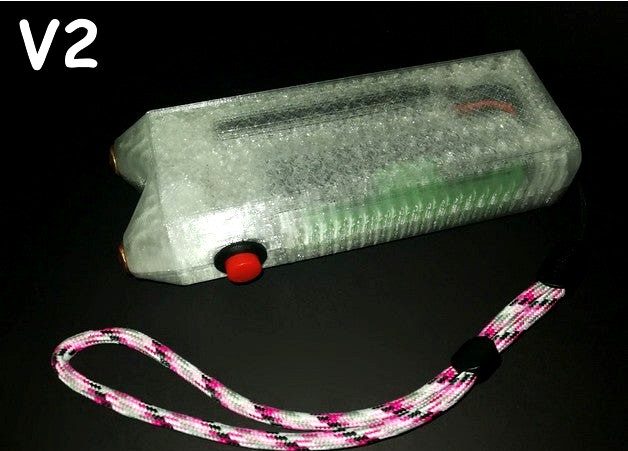
Ms. Zappy V2 - A cute, pocket-able and tacticool stun gun! by Odd_321
by Thingiverse
Last crawled date: 3 years, 3 months ago
NOW UPDATED TO V2 TACTICOOL EDITION
Interesting stuff
Tacticool ribs for maximum grippage
Subtle contours for increased feminine charm
Lanyard attachment variant included for when things get messy
Boring stuff
Length increased by 2mm to allow greater recess of rear rocker
Increased diameter of the pushbutton hole to ensure tight seams
Arc gap widened to allow arc up to 12mm.
Ms. Zappy
Meet Ms. Zappy, she's a cute little stungun, super cheap, easy to build using standard components and she packs a punch.
My priorities in this design were to use space efficiently, creating something compact yet ergonomic, for all components to be readily available and cheap and for the printed parts to print without support.
I don't know what Thingiverse's rules are regarding items like this, there are a lot of far more dangerous things on here but I am posting this under a new account in case it incites a ban.
Component list:
Please note, I do not endorse the individual sellers in the links below, I include them simply for reference.
1x TP4056 charging module - Link
1x 18650 holder - Link
1x Momentary push button - Link
1x Illuminated rocker - Link
1x 400kV pulse module - Link
1x 18650 cell
4x 20mm M3 socket cap machine screws
2x Nails
Some wire
Basic soldering equipment/skills
The casing prints easily, everything should slot into place. The charging module snaps into place firmly and is held tight to allow secure insertion and removal of a charging lead. There are channels and pockets to allow wiring to be routed.
The electricals are straightforward with a couple of caveats. These TP4056 boards have over-discharge protection at <2.5v and over-current protection at >3a. This is a problem for us as we want to draw (marginally) more than 3a.
On the bench the pulse modules tested like this:
@3.5v - 3a
@3.7v - 3.2a
@4.2v - 3.5a
This was with a spark gap of 5mm. I tested again at 10mm and was surprised to get the exact same results.
So, we will be pushing enough current to trip the protection circuit and in testing this did occur. To avoid this I bypassed the boards outputs, connecting the pulse module directly to the bat +/-, with the positive still running through the switches. This solves the issue but obviously now the battery is free to drain to a damaging level, I don't think this a major problem for this device as it is not intended to be used continuously or for extended periods and you're not going to drain it down with a few short bursts. You could use a battery with an integrated low voltage cut-off to mitigate this problem.
Second issue, regarding the external arc/spark gap. Everyone loves cool flashy arcs but these pulse modules are whack. I've tested them with a gap up to 16mm but they don't live very long. For this reason I kept the spark gap on mine short, 6mm to be precise. Feel free to increase/decrease this as desired, the design as is allows for a gap of up to 10mm but it's easily edited. Even with a narrow gap this is for intermittent and short use, like for a second or less at a time, I burnt through three modules during testing, it's a good thing they're cheap because they are fragile, buy multiple!
Wires should be soldered to the backside of the charging board, the case is designed around this. If you solder to the top, the wires will interfere with the case. I've included a picture showing how I wired things up. That is literally the limit of my circuit diagram proficiency.
For the terminals I used square shank copper nails, 3.6mm square. They were sold to me as "boat nails", feel free to substitute them for something else and adjust the model accordingly.
For the spark gap I used a couple of bits of single stranded wire, these can be substituted for something else, multi-strand wire, needles, nails etc.. You could bend nails into an "L" shape for both the terminal and the arc gap but that seems like a hassle to me.
The M3 screws thread directly into the casing, this is something I do a lot and it works well for items that rarely need to be opened.
The TP4056 board has LEDs to indicate battery status during charging, I used a translucent filament to make these visible.
Similar models
thingiverse
free

TP4056 1A 5V Lithium Battery 18650 Charging Board Module case by slibbinas
...ttery 18650 charging board module case.
printed in pla
both sides fits. you can use pair drops of superglue to keep them together
thingiverse
free

18650 tp4056 module by woojung
...18650 tp4056 module by woojung
thingiverse
this is a 18650 battery case, charge module
thingiverse
free

TP4056 charging module by Dmawzx
...tp4056 charging module by dmawzx
thingiverse
this is an approximate tp4056 3d model.
i used it to develop a radio control.
thingiverse
free

MPCNC Laser alignment by spinne
...randed wire. use a lot of solder and spread the little wires, to form a big contact pad.
if needed, glue the tp4056 to the plate.
thingiverse
free

Battery charger for CRC123A RC123A using TP4056 module by cmag16
...were hot glued.
i stripped the wire to fit through the holes, just to make it more compact and keep the wire flush to the bottom.
grabcad
free

TP4056 charge module with protection
...tp4056 charge module with protection
grabcad
tp4056 charge module with protection
with type-c connector
thingiverse
free

Velleman MK194N radio case by 3DSmile
...thing:4668173 to somewhat improve audio quality.
future updates:
-add usb port for charging
-add battery
-add retractable antenna
grabcad
free

18650 Battery Charging Holder Charging Board TP4056
...18650 battery charging holder charging board tp4056
grabcad
18650 battery charging holder charging board tp4056
thingiverse
free

TP4056 18650 Holder Charger by zeroeffekt
...lue them in place.
it's easier if you solder the wires to the tp4056 then slide it in place and then solder the contacts on.
thingiverse
free

SJCam SJ4000 battery charger by paulkennett
...sign - and it works beautifully.
oh - and the reason i don't just charge the sj cam via its usb cable it i busted its socket.
Zappy
thingiverse
free

Zappies - ClashRoyale - Electrocuteurs by bollibe
...shroyale electrocuteurs
separated parts can be assembled together
made with pla silver, wood and glow green
designed in fusion360
thingiverse
free

Zappies - ClashRoyale - Electrocuteurs by bollibe
...zappies - clashroyale - electrocuteurs 3d printed (silver - wood - glow green)
all parts 3d printed separatly can be assembled
thingiverse
free

Key mount for handlebar by commtechva
...handlebar by commtechva thingiverse key mount for handlebar on zappy ...
thingiverse
free

ZButt Stem Cavity Mod
...stem cavity mod thingiverse this is a remix of zappy#39;s stem cavity, purpose to make it is because i...
thingiverse
free

Weather proof holster for exterior EV charge plug by chrishornby
...ne was designed specifically for the zappi solar charging unit. ymmv. i have included 123dx files if you wish to change anything.
cg_trader
free

Toy Zappy Gun
...plastic toy pistol
made up of several different named and grouped parts, materials have been used, like lambert, blinn and phong.
cg_trader
free

clash roya
...clash roya cg trader i made for you a zappy of clash royal clashroyal zappy arme vehicule game jeu...
3dwarehouse
free

plutonium reactor with govenor (zappy lazer)
... have the barium/radium core. beyond that, the 4 plutonium rods and lead govenor #atomic #cool #fun #lazer #nuclear #space #zappy
3dwarehouse
free

Green Point Stadium textures by zappy bibicy
...eroen_hut #kaap #kaapstad #point #point_stadium #stadium #wereld #wereld_kampioenschap #wk #world #world_championship #zuidafrika
Tacticool
thingiverse
free

Tacticool Keychain by Conceptor
... keychain by conceptor
thingiverse
here is the tacticool keychain inspired by the famous multifunction knife of the swiss army !
thingiverse
free

TactiCool Pen by mussy
...it driver & pen all in one tool.
!don't forget to check out my other designs and follow my daily kookoo uploads, enjoy ;)
thingiverse
free

Console Housing for Ultimate Digital Tacticool Project by flemdogmillionaire
...l project. files are in inches.
bitbucket repository for the project: https://bitbucket.org/flemdogmillionaire/ultimate_tacticool
thingiverse
free

Lynx SciFi Tacticool Shroud by Rzt4097
...icool shroud by rzt4097
thingiverse
remix of https://www.thingiverse.com/thing:4629645, requires the pump from there to function
thingiverse
free

Tacticool Disposable Drinking Straw by MechNugget
...rinking straw by mechnugget
thingiverse
i make no warranty claim that your printer is good enough to print this. mine isn't.
thingiverse
free

Tacticool Nestor Picatinny Foregrip by veeectorm2
...ed tactical attachments, i bring you the nestor head bust foregrip, compatible with any picatinny rail system pistol or sbr. etc.
thingiverse
free

Tacticool Nerf Mag Holder by cdamet23
... on the way soon, possibly including lego compatible versions of the halo br55 battle rifle, m6c magnum, and the arc-920 railgun!
thingiverse
free

Lynx Angled Talon Magwell Grip for Tacticool Guard by o0Maiker0o
...ww.thingiverse.com/thing:4887803 to include the cutout for use with the hand guard from https://www.thingiverse.com/thing:4629645
thingiverse
free

Alpha trooper picatinny grip, with 3 dot sights and more tacticool rail by Maxii008
...ts and more tacticool rail by maxii008
thingiverse
fits all alpha troopers. picatinny is weaker so print with abs, pet-g or asa.
thingiverse
free

Mega Caliburn Tacticool Handguard
...hole thing straight. i have not tested the functionality of the m-lok, clearance between bolt arms and the m-lok might be tight.
321
3d_export
$55

Condo 321 3D Model
...iture accessories complete full detailed photorealistic textures materials render ready
condo 321 3d model barmoon 42666 3dexport
3d_export
$155

Building 321 3D Model
...terior resort hotel bank office center university college campus street landscape
building 321 3d model rosestudio 54823 3dexport
3d_export
$60

Architecture 321 3D Model
...lege campus max street landscape commercial building medical hospital offices
architecture 321 3d model lotusmodel 47983 3dexport
3d_export
$160

3d building 321 3D Model
...erior vray sitting accesorie apartment home visualization sofa couch table chair
3d building 321 3d model kanhtart 44312 3dexport
3d_export
$50

3D Home 321 3D Model
... chair furniture texture table lamp apartment rug carpet restaurant hotel sitting
3d home 321 3d model richard3015 46125 3dexport
3d_ocean
$190
321 Comprehensive Building Materials Pack for C4D
...on description: this is all-in-one library of my building material series which contains 10 libraries. this comprehensive libr...
3ddd
$1

Самшит
...самшит 3ddd самшит , куст , изгородь polys : 321 680 verts : 246...
3ddd
$1

VALELUNGA - PIETRE DEI CONSOLI
...pietre dei consoli 3ddd итальянская фабрика. плитка нескольких типоразмеров: 321321 и 481*481 мм. в архиве два цвета - ноче...
3d_export
$100

Airbus A321 Air France 3D Model
...ne air france plane planes airplane airplanes aircraft aircrafts airliner
airbus a321 air france 3d model behr bros 3558 3dexport
3d_export
$95

Ferrari Enzo 3D Model
...enzo sport car f1 ferrari enzo 3d model dellorto85 321 ...
Odd
3ddd
$1

Leisure odd chair
...leisure odd chair
3ddd
leisure , odd
leisure odd chair
3d_export
free

favourite odd 2826-6p
...favourite odd 2826-6p
3dexport
the model based on the photos.
turbosquid
$35

The Odd Chair Company Bovina chaise
... available on turbo squid, the world's leading provider of digital 3d models for visualization, films, television, and games.
3ddd
free

The Odd Chair Company, "Hudson Chair"
... hudson
модель low poly, в двух варриантах.http://www.theoddchaircompany.com/collections/hudson-chair/
3d_export
$34

AirTruck 3D Model
...3ds model transavia air truck weird wierd strange odd oddty crop duster mad max road warrior prop gyro captain...
3d_ocean
$6

Squid Lamp
...squid lamp 3docean bulb desk florescent lamp lavender light odd office squid table the squid table lamp is 35,579...
3d_export
$35

Chaparral 2J 3D Model
...le mans american sports car speed grip innovative innovation odd shape aerodynamic lola racing exotic power chaparral 2j 3d...
3d_ocean
$5

Yellow Brick Road Seamless Texture
...building cobblestones fairy fantasy garden gold ground magic magical odd park path scarecrow stones strange walkway wall weird wizard...
3d_export
$5

tampon low-poly
...for both, but in my opinion it looks quite odd if you use the normal, so i don't recommend...
3d_export
$17

fictional old stadium 2 - national rugby arena
...in the east and west higher tier, which look odd but it is the kind of modification that are...
Stun
turbosquid
$10

Stun
...un
turbosquid
royalty free 3d model stun for download as 3ds on turbosquid: 3d models for games, architecture, videos. (1167241)
turbosquid
$5

Stun Gun
...yalty free 3d model stun gun for download as ma, obj, and fbx on turbosquid: 3d models for games, architecture, videos. (1301219)
turbosquid
$10

Stun Grenade
... available on turbo squid, the world's leading provider of digital 3d models for visualization, films, television, and games.
turbosquid
$10

Stunning Seren
... available on turbo squid, the world's leading provider of digital 3d models for visualization, films, television, and games.
turbosquid
free

Stun Gun
... available on turbo squid, the world's leading provider of digital 3d models for visualization, films, television, and games.
3d_export
$15

m84 stun grenade
...tallic.tga<br>(r-ambient occlusion / g-roughness / b-metallic)<br>feel free to message me.<br>piotr jaros 2020.
turbosquid
free

woman in stunning suit
...alty free 3d model woman in stunning suit for download as max on turbosquid: 3d models for games, architecture, videos. (1585706)
turbosquid
free

woman in a stunning jacket
... free 3d model woman in a stunning jacket for download as max on turbosquid: 3d models for games, architecture, videos. (1585654)
turbosquid
$16

M84 Stun Grenade
...ty free 3d model m84 stun grenade for download as fbx and obj on turbosquid: 3d models for games, architecture, videos. (1587586)
turbosquid
$15

M84 Stun Grenade
...ty free 3d model m84 stun grenade for download as max and fbx on turbosquid: 3d models for games, architecture, videos. (1223274)
Ms
3ddd
$1

Smania ms/g0006
...smania ms/g0006
3ddd
smania
диван smania, арт: ms/g0006
turbosquid
$65

CBJ-MS
...alty free 3d model cbj-ms for download as obj, fbx, and blend on turbosquid: 3d models for games, architecture, videos. (1230037)
turbosquid
$9

Interceptor MS
... available on turbo squid, the world's leading provider of digital 3d models for visualization, films, television, and games.
3d_export
$25

Beyblade Driger MS 3D Model
...beyblade driger ms 3d model
3dexport
beyblade driger ms metal slash ray kon
beyblade driger ms 3d model alexsikdar 94763 3dexport
turbosquid
$20

Jar With m&ms
... available on turbo squid, the world's leading provider of digital 3d models for visualization, films, television, and games.
3ddd
$1

HOHNER 580 Meisterklasse MS
... губная гармонь
модель hohner 580 meisterklasse ms с текстурами для наполнения интерьера.
3d_export
$30

sanitizer ms structure
...sanitizer ms structure
3dexport
sanitizer tunnel for sanitize person by passing though tunnel .
turbosquid
$1

First Person CBJ-MS
...ee 3d model first person cbj-ms for download as fbx and blend on turbosquid: 3d models for games, architecture, videos. (1427151)
3ddd
$1

Stickley ms 80114
...stickley ms 80114
3ddd
new england , stickley
автор модели: aeroslon
3ddd
$1

Аккустическая система Sven MS 320
... аккустика , sven
аккустическая система sven ms 320 (2 колонки и саб)
3d_export
$12

pocket stove
...pocket stove
3dexport
pocket stove
3d_ocean
$6

Pocket Watch
...calendar chain clock gear gold golden jewelry luxury old-fashioned pocket pocket watch time watch
pocket watch on a 2009 calendar
3d_export
$5

Pocket Watch
...pocket watch
3dexport
pocket watch old style
3d_ocean
$15

pocket watch
... calendar chain clock gear gold golden jewelry luxury old-fashioned pocket pocket watch time watch
high poly ancient pocket watch
3d_export
$8

Pocket watch
...pocket watch
3dexport
pocket watch with a photo of new york in the 1900s
turbosquid
$5

Pocket flashlight
...uid
royalty free 3d model pocket flashlight for download as on turbosquid: 3d models for games, architecture, videos. (1271804)
3d_export
free

Pocket flashlight
...this is a 3d model of a pocket flashlight. it is quite realistic and you can add this model to your project and enjoy the result.
archive3d
free

Pocket 3D Model
...e3d
bag pocket paper bag
pocket n040608 - 3d model (*.gsm+*.3ds) for interior 3d visualization.
turbosquid
$20

Pocket Watch
...squid
royalty free 3d model pocket watch for download as c4d on turbosquid: 3d models for games, architecture, videos. (1352289)
turbosquid
$5

Pocket Knife
...uid
royalty free 3d model pocket knife for download as blend on turbosquid: 3d models for games, architecture, videos. (1560181)
Cute
turbosquid
free

cute
... available on turbo squid, the world's leading provider of digital 3d models for visualization, films, television, and games.
3d_export
free

cute cactus
...cute cactus
3dexport
cute and happy cactus with a flower that can be used for games and background filling
3d_ocean
$15

Cute Bee
... bee character cute fauna game insect small yellow
3d model of cute looking bee, 2258 total polygon optimized for high poly model
turbosquid
$3

cute robot
...turbosquid
royalty free 3d model cute robot for download as on turbosquid: 3d models for games, architecture, videos. (1485400)
turbosquid
$199

Cute-Alien
...rbosquid
royalty free 3d model cute-alien for download as ma on turbosquid: 3d models for games, architecture, videos. (1294878)
turbosquid
$39

Cute Seat
...rbosquid
royalty free 3d model cute seat for download as max on turbosquid: 3d models for games, architecture, videos. (1235238)
turbosquid
$20

robot cute
...bosquid
royalty free 3d model robot cute for download as obj on turbosquid: 3d models for games, architecture, videos. (1435509)
turbosquid
$20

cute warrior
...uid
royalty free 3d model cute warrior for download as blend on turbosquid: 3d models for games, architecture, videos. (1455650)
3d_ocean
$15

Cute Girl
...rl
3docean
child female girl human people
cute girl! it was created with cinema4d r15 and the file formats include an .c4d, .obj.
turbosquid
$5

Deer Cute
...osquid
royalty free 3d model deer cute for download as blend on turbosquid: 3d models for games, architecture, videos. (1568299)
V2
3d_export
free
Lamp v2
...lamp v2
3dexport
lamp v2 with solar panel
3d_export
$5

hammerhead v2
...hammerhead v2
3dexport
razer hammerhead v2 headphones, modeled in cinema 4d, render in corona
3d_export
$5

manometer v2
...manometer v2
3dexport
3d_export
$5

potato v2
...potato v2
3dexport
turbosquid
$52

Lifebuoys v2
...squid
royalty free 3d model lifebuoys v2 for download as fbx on turbosquid: 3d models for games, architecture, videos. (1560870)
turbosquid
$2

Mask v2
...turbosquid
royalty free 3d model mask v2 for download as stl on turbosquid: 3d models for games, architecture, videos. (1527741)
turbosquid
free
Flashlight V2
...d
free 3d model flashlight v2 for download as , obj, and fbx on turbosquid: 3d models for games, architecture, videos. (1663559)
turbosquid
$20

Kitchen V2
...ty free 3d model kitchen v2 for download as max, obj, and fbx on turbosquid: 3d models for games, architecture, videos. (1155111)
turbosquid
$20

kengkod64-v2
... free 3d model kengkod64-v2 for download as 3dm, ztl, and stl on turbosquid: 3d models for games, architecture, videos. (1701415)
turbosquid
$19

Chair v2
...yalty free 3d model chair v2 for download as ma, obj, and fbx on turbosquid: 3d models for games, architecture, videos. (1693360)
Gun
archibase_planet
free

Gun
...t
gun tommy gun thompson gun thompson submachine gun
gun thompson n120313 - 3d model (*.gsm+*.3ds) for interior 3d visualization.
archibase_planet
free

Gun
...gun
archibase planet
gun machine-gun submachine gun
gun m4a1 n260713 - 3d model (*.gsm+*.3ds+*.max) for 3d visualization.
archibase_planet
free

Gun
...base planet
gun submachine gun sub-machine-gun
gun fn scar mark16 n091210 - 3d model (*.gsm+*.3ds) for interior 3d visualization.
archibase_planet
free

Gun
...gun
archibase planet
gun rifle hand-gun
gun n221010 - 3d model (*.gsm+*.3ds) for interior 3d visualization.
archibase_planet
free

Gun
...gun
archibase planet
gun automatic machine machine gun
gun p90 n020515 - 3d model (*.gsm+*.3ds+*.max) for 3d visualization.
archibase_planet
free

Gun
...gun
archibase planet
gun automatic rifle submachine-gun
gun m4 n221112 - 3d model (*.gsm+*.3ds) for interior 3d visualization.
archibase_planet
free

Gun
...gun
archibase planet
gun m16 machine gun
gun m16 n030613 - 3d model (*.gsm+*.3ds+*.max) for interior 3d visualization.
archibase_planet
free

Gun
...gun
archibase planet
machine-gun gun fire-arms shooter
gun n270211 - 3d model (*.gsm+*.3ds) for interior 3d visualization.
archibase_planet
free

Gun
...hibase planet
gun automatic machine machine gun
gun jackhammer mk3a1 n290415 - 3d model (*.gsm+*.3ds+*.max) for 3d visualization.
archibase_planet
free

Gun
...n
archibase planet
paintball gun gun paintball
gun paintball bt 4 renta n280611 - 3d model (*.3ds) for interior 3d visualization.
Able
3d_export
$25

fitness male abl 31400001
...fitness male abl 31400001
3dexport
turbosquid
$10

Stick-able Push Light
...d model stick-able push light for download as sldpr and sldas on turbosquid: 3d models for games, architecture, videos. (1377346)
turbosquid
$9

ABLE Dollar X Token black coin
...e 3d model able dollar x token black coin for download as max on turbosquid: 3d models for games, architecture, videos. (1592200)
turbosquid
$9

ABLE Dollar X Token gold coin
...ee 3d model able dollar x token gold coin for download as max on turbosquid: 3d models for games, architecture, videos. (1592152)
3d_ocean
$2

2 Geometric Fabric Tile Able Textures
...rn composition. in 2048×2048 pixels of resolution. don´t forget to rate my items if you consider them useful. if you have any ...
3d_ocean
$2

Hand Painted Tile-able Wooden Roof Shingles
...ble professional looking texture. size: 1024×1024 and 512×512 also check out my other works on envato http://audiojungle.net/u...
3d_ocean
$2

Basic Tile-able Wooden Planks - Hand Painted
...ble professional looking texture. size: 1024×1024 and 512×512 also check out my other works on envato http://audiojungle.net/u...
3d_ocean
$2

Basic Tile-able Stone Floor - Hand Painted
...ble professional looking texture. size: 1024×1024 and 512×512 also check out my other works on envato http://audiojungle.net/u...
3d_ocean
$2

Basic Tile-able Stone Wall - Hand Painted
...ble professional looking texture. size: 1024×1024 and 512×512 also check out my other works on envato http://audiojungle.net/u...
3d_ocean
$2

Basic Tile-able Brick Floor - Hand Painted
...ble professional looking texture. size: 1024×1024 and 512×512 also check out my other works on envato http://audiojungle.net/u...