Thingiverse
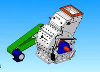
Increased milling space for R-CNC, the printable milling machine by ewald
by Thingiverse
Last crawled date: 3 years ago
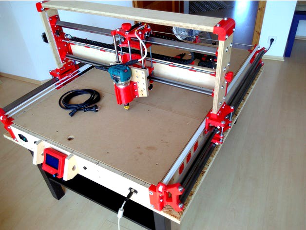
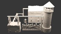
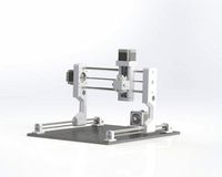
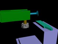
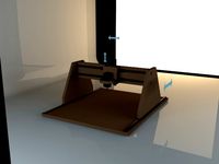
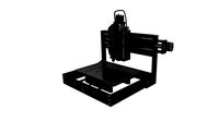
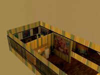
I am currently building a modified version of R-CNC, the printable milling machine. Since the original design is too small for my woodworking needs, I intend to blow it up a bit:
Increasing the width is easiest: add 200mm to all the original measurements.
More depth is a bit trickier as sturdiness degrades by the power of two when just increasing the length of the side tubes. In a first step I will go with the original 25mm tubes but 1200mm length and then test bending. So just adding 450mm to all the orginal measurements. If bending turns out too bad, I will either swap the corner pieces with holders for 40mm tubes or I will add a second 25mm tube below - which is more complicated and less likely to happen. So the 40mm solution is already part of this upload.
Another simple solution might be to insert a matching flat bar vertically into the tube and glue it on the full length of the corners. Maybe just flooding the corners with epoxy resin.
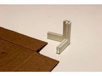
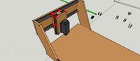
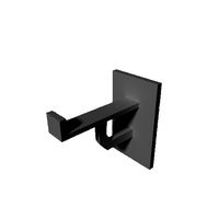
Adding more clearance below the router requires stretching the x-fixations and shifting them upwards. All the original measurements are increased by 50mm, except the two side pieces which will probably need at least additional 80mm. Since the resulting X-fixation was too big for common 3D printers like mine, I cut the piece in half and added small hooks. You probably need to file the hooks a bit once printed.
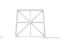
There is also an updated drilling template for paper prints. You will need to scale it correctly: print it, calculate the required scaling factor by dividing real measurement on paper by the printed value. Then print the second time. Afterwards fold it at the designated line and place the fold at the front sides to mark the locations. Be sure to shift equally on both sides.
Please note that as of now this is work in progress and the one the or the other detail might change for better performance.
Update 2017-07-23:
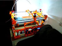
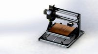
I am mostly done ;-)
Contrary to first assumptions, a 40mm tube is too big, is covers part of the space for the belt. So I added a second tube with 25mm below the original one. Additionally there are screws in the bottom board to support the second tube.
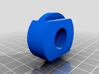
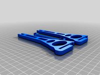
This project now contains virtually all my files. Each STL is accompanied by a JPG of the same name so you have an idea about the intended purpose and location. I omitted the Sketchup files. Should you want them, drop me a note.
I hacked the Marlin files a bit to make the endstops work and to display the current state on the otherwise empty space on the LCD.
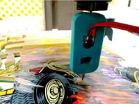
I also added support for a Z probe which acts as a second ZMIN for homing. Now I can wire up the router bit and place a thin piece of wired metal on top of my stock and have it homing.
Update 2018-03-04:
The sources with my modifications are all on Github
Since Marlin was not intended as software for a CNC, it does not understand every such gcode file. My current workflow comprises FreeCAD and the LinuxCNC or GRBL preprocessor. Just make sure, the output is not shortened as each line is required to contain X, Y, and Z-code like the following. There was a switch to accomplish just that bad setting, but I can't reproduce it right now.
G0 X109.8144 Y548.0000 Z13.0000
Increasing the width is easiest: add 200mm to all the original measurements.
More depth is a bit trickier as sturdiness degrades by the power of two when just increasing the length of the side tubes. In a first step I will go with the original 25mm tubes but 1200mm length and then test bending. So just adding 450mm to all the orginal measurements. If bending turns out too bad, I will either swap the corner pieces with holders for 40mm tubes or I will add a second 25mm tube below - which is more complicated and less likely to happen. So the 40mm solution is already part of this upload.
Another simple solution might be to insert a matching flat bar vertically into the tube and glue it on the full length of the corners. Maybe just flooding the corners with epoxy resin.
Adding more clearance below the router requires stretching the x-fixations and shifting them upwards. All the original measurements are increased by 50mm, except the two side pieces which will probably need at least additional 80mm. Since the resulting X-fixation was too big for common 3D printers like mine, I cut the piece in half and added small hooks. You probably need to file the hooks a bit once printed.
There is also an updated drilling template for paper prints. You will need to scale it correctly: print it, calculate the required scaling factor by dividing real measurement on paper by the printed value. Then print the second time. Afterwards fold it at the designated line and place the fold at the front sides to mark the locations. Be sure to shift equally on both sides.
Please note that as of now this is work in progress and the one the or the other detail might change for better performance.
Update 2017-07-23:
I am mostly done ;-)
Contrary to first assumptions, a 40mm tube is too big, is covers part of the space for the belt. So I added a second tube with 25mm below the original one. Additionally there are screws in the bottom board to support the second tube.
This project now contains virtually all my files. Each STL is accompanied by a JPG of the same name so you have an idea about the intended purpose and location. I omitted the Sketchup files. Should you want them, drop me a note.
I hacked the Marlin files a bit to make the endstops work and to display the current state on the otherwise empty space on the LCD.
I also added support for a Z probe which acts as a second ZMIN for homing. Now I can wire up the router bit and place a thin piece of wired metal on top of my stock and have it homing.
Update 2018-03-04:
The sources with my modifications are all on Github
Since Marlin was not intended as software for a CNC, it does not understand every such gcode file. My current workflow comprises FreeCAD and the LinuxCNC or GRBL preprocessor. Just make sure, the output is not shortened as each line is required to contain X, Y, and Z-code like the following. There was a switch to accomplish just that bad setting, but I can't reproduce it right now.
G0 X109.8144 Y548.0000 Z13.0000
Similar models
thingiverse
free
Cardboard Box Corner Joint by laserguru
...ed, but a dab of uhu or white glue will solve it if not.
a second file includes a smaller version, 25mm on the sides x 40mm tall.
thingiverse
free

TIL-Fusion360 - MyFirst CNC by lmnewey
...than a fixed gantry. intended to be fitted with a router, laser, plasma cutter and 3d printing head possibly multi extrusion head
thingiverse
free

Bowden Tube Cutter for Ender by lysithea81
...increased thickness of fragile parts for improved strength (i had printed the original design, which worked great, but it broke).
thingiverse
free
CNC-Probe by eduard80
...w.youtube.com/watch?v=r1olty4r90q&feature=youtu.be
https://www.invented.tech.blog
https://www.instructables.com/id/cnc-probe/
thingiverse
free

Pegboard Pliers Holder that Holds 2 by Gabeff
...lder was a little bit too wide- and i have quite a few pairs.
so i thinned it out just a bit, and added a second holder on to it!
thingiverse
free
![Tube Corner Joint (3 way) [25mm] by JamesCoyle](/t/8674306.jpg)
Tube Corner Joint (3 way) [25mm] by JamesCoyle
...er diameters if requested. if you need this part to connect a different number of tubes. get in touch and i can upload those too.
thingiverse
free
Tevo tarantula dual inverted Z oldham middle section by moderboy
...op side is great, the lower side is a bit larger than it is supposed to be, needs more sanding than it is intended to originally.
thingiverse
free
Marlin CoreXY skew test 200mm x 200mm remix by gallaghersart
...re precise areas to measure.
no type markings to speed up prints, just one coroner is different. this should be “a”.
enjoy!
`mike
thingiverse
free

Skadis Tube Holder Wide by piano333
...t's cause of my slicer of whatever, but i modified the model and figured i'd post in case anyone else has the same issue.
thingiverse
free
Prusa i3 (L frame) Spool Holder by abrokadabra
...quot;long" version has an additional 25mm added to its width, since certain spools are too wide for the normal center-piece.
Ewald
thingiverse
free
BigPrinter Customization by ewald
...same rod)
z: rod/profile: 350
the short vertical profiles for the middle carrier profile is 170 but could be anything you need.
free3d
$6

T-34 (1940)
...finest tank in the world” —field marshal paul ludwig ewald von kleist (liddell hart 1951) combat effectiveness of early...
grabcad
free

Zirkon
...did about 15 years ago for german r/c pilot ewald trumpp. mickey is from grabcad - mickey et...
grabcad
free

Paul Ludwig
...paul ludwig grabcad paul ludwig ewald von kleist (8 de agosto de 1881 – 13...
cg_trader
$12
T34-85 D-5T Medium Tank
...encountered the tank in 1941, german general paul ludwig ewald von kleist called it the finest tank in the...
grabcad
free

The unique future electric car system design
...future electric car system design grabcad hi . i'm ewald geduld. and i love to design the future in...
grabcad
free

J.G special unique house design
...i like to hear from you. email j.geduld@hotmail.com greetings ewald geduld. j.g...
grabcad
free

THE FUTURE SANDWICH CAR DESIGN
...the future sandwich car design grabcad hi i'm ewald geduld. i'm looking for money people for help my...
grabcad
free

J.G Design The unique G, robotics future car,s design
...unique g, robotics future car,s design grabcad hi i'm ewald geduld. i'm looking for money people for help my...
Milling
design_connected
$18
Mills
...mills
designconnected
minotti mills computer generated 3d model. designed by dordoni, rodolfo.
3ddd
$1

Mille Nuits
...mille nuits
3ddd
mille nuits
люстра из коллекции mille nuits
turbosquid
$25

Mill
...ll
turbosquid
royalty free 3d model mill for download as fbx on turbosquid: 3d models for games, architecture, videos. (1292872)
turbosquid
$15
The Mill
...urbosquid
royalty free 3d model the mill for download as obj on turbosquid: 3d models for games, architecture, videos. (1459219)
turbosquid
$3
Mill
...ll
turbosquid
royalty free 3d model mill for download as max on turbosquid: 3d models for games, architecture, videos. (1233201)
turbosquid
$1

mill
...
turbosquid
royalty free 3d model mill for download as blend on turbosquid: 3d models for games, architecture, videos. (1613409)
3d_export
$10
Coffee Mill
...coffee mill
3dexport
coffee mill
3d_export
$5
impact mill
...impact mill
3dexport
impact mill
archibase_planet
free
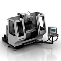
Milling machine
...base planet
milling machine miller milling-machine
milling machine vhf-680 n250413 - 3d model (*.gsm+*.3ds) for 3d visualization.
3ddd
$1
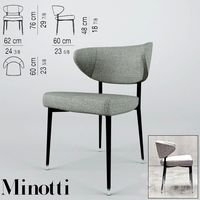
Minotti / Mills
...minotti / mills
3ddd
minotti
minotti / mills
Increased
3d_export
$15

among us
...among us
3dexport
turbosmooth modifier can be used to increase mesh resolution if necessary
3d_export
free
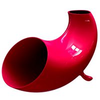
phone amplifier
...phone amplifier
3dexport
this model can stand up a medium cellphone and increase the voice in analog way.
3d_export
$5
V-Barracks
...xport
medieval barracks for training fighters for battle. dummies and pendulums will help fighters increase their survivability.
3d_export
$5
hookah
...thout water and without hoses. you have to apply the subdivision surface modifier in the .blend (the polygon count will increase)
3d_export
$70
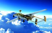
Of IAI Searcher 10 modified UAV
...glider searcher, which is modified as follows:<br>increased wing span. increased fuselage length. turboprop installed<br>120 hp engine.<br>air propeller. the dimensions...
3ddd
$1

Mesquite Tree
...дерево
mesquite tree for desert scenes.
growfx file included to increase and decrease the quality and make many different trees.
3d_export
$50

glider aircraft
...
glider design the glider has a long wingspan of 1.5 m motor to increase thrust contains 3 fans frame material balsawood or fiber
3d_export
free
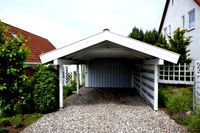
carports adelaide
...ing your space, enhancing security and increasing the appeal of your home? you require our premium carports in adelaide. [b] [/b]
3d_export
$25
The destroyer of the forts the modified frigate 3D Model
...clipper gun fourth warship sailboat sail frigate with the increased quantity and calibre of tools for bombardment of...
3d_export
$12
Nitro bottle 3D Model
...tro nos laughgas speed car motor engine increase injection nitrous oxide bottle
nitro bottle 3d model demigamer666 76696 3dexport
R
3ddd
$1
ORLANDO R
...orlando r
3ddd
новый стиль
новый стиль - orlando r
design_connected
$11
R-Table
...r-table
designconnected
henge r-table computer generated 3d model. designed by castagna, massimo.
design_connected
$7

Cone R
...cone r
designconnected
bonaldo cone r computer generated 3d model. designed by pasini, ennio.
3ddd
$1

R&B
...r&b
3ddd
r&b
спальный гарнитур r&b;
3d_export
$5

nissan gt-r
...nissan gt-r
3dexport
this is nissan gt-r
turbosquid
$10

R for ROBOT
...osquid
royalty free 3d model r for robot for download as max on turbosquid: 3d models for games, architecture, videos. (1694233)
turbosquid
$5

Letter r
...urbosquid
royalty free 3d model letter r for download as max on turbosquid: 3d models for games, architecture, videos. (1408525)
turbosquid
$5

Letter R
...urbosquid
royalty free 3d model letter r for download as max on turbosquid: 3d models for games, architecture, videos. (1408526)
3d_export
$5

react r
...r 9 lamps (6+3) ø 60 × 21 cm 12 lamps (9+3) ø 80 × 21 cm polys: 208 539 verts: 213 675 https://ru.lampachn.com/react-r-p0551.html
turbosquid
$40
R-73
...uid
royalty free 3d model r-73 for download as blend and fbx on turbosquid: 3d models for games, architecture, videos. (1620664)
Cnc
3d_export
$35
Cnc
...cnc
3dexport
the cnc machine is unfinished
3d_export
$10
cnc router
...cnc router
3dexport
prototipe cnc router
3d_export
$10
cnc machine
...cnc machine
3dexport
cnc machine model with individual model files with assembly
3d_export
$5
Cnc 3D Model
...cnc 3d model
3dexport
cnc
cnc 3d model csiszar 61289 3dexport
turbosquid
$10

cnc bedroom
...osquid
royalty free 3d model cnc bedroom for download as max on turbosquid: 3d models for games, architecture, videos. (1494981)
turbosquid
$9
cnc(wood)
...rbosquid
royalty free 3d model cnc(wood) for download as max on turbosquid: 3d models for games, architecture, videos. (1189189)
turbosquid
$1

CNC Frame
...rbosquid
royalty free 3d model cnc frame for download as stl on turbosquid: 3d models for games, architecture, videos. (1371706)
turbosquid
free
cnc table
...rbosquid
royalty free 3d model cnc table for download as max on turbosquid: 3d models for games, architecture, videos. (1500926)
turbosquid
$30
CNC Lathe
...
royalty free 3d model cnc lathe for download as max and obj on turbosquid: 3d models for games, architecture, videos. (1284634)
turbosquid
$25
CNC Machine
...
royalty free 3d model cnc machine for download as ma and fbx on turbosquid: 3d models for games, architecture, videos. (1307199)
Machine
archibase_planet
free

Machine
...machine
archibase planet
sewing-machine sewing machine equipment
singer machine- 3d model for interior 3d visualization.
archibase_planet
free

Machine
...hine
archibase planet
percolator equipment coffee-machine
machine n230708 - 3d model (*.gsm+*.3ds) for interior 3d visualization.
archibase_planet
free
Machine
...chibase planet
percolator coffee-machine kitchen equipment
coffee machine - 3d model (*.gsm+*.3ds) for interior 3d visualization.
archibase_planet
free
Slot machine
...ase planet
slot machine slot-machine playing machine
slot machine n260311 - 3d model (*.gsm+*.3ds) for interior 3d visualization.
turbosquid
$7

Machine
...ne
turbosquid
royalty free 3d model machine for download as on turbosquid: 3d models for games, architecture, videos. (1391792)
3d_ocean
$10
War machine
...war machine
3docean
camuflage machine robot war war machine
war machine created in 3dmax 2009 15.497-poly count
turbosquid
$7

machine
...turbosquid
royalty free 3d model machine for download as obj on turbosquid: 3d models for games, architecture, videos. (1452674)
3d_ocean
$12
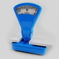
Weighing-machine
...weighing-machine
3docean
market shop weighing-machine
3d model weighing-machine
archibase_planet
free

Sewing machine
...ine
archibase planet
sewing machine sewing-machine
sewing machine n080311 - 3d model (*.gsm+*.3ds) for interior 3d visualization.
archibase_planet
free
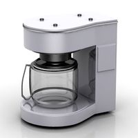
Coffee machine
...se planet
coffee machine percolator coffee-machine
coffee machine n010715 - 3d model (*.gsm+*.3ds) for interior 3d visualization.
Printable
turbosquid
$5
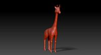
printable giraffe
...uid
royalty free 3d model printable giraffe for download as on turbosquid: 3d models for games, architecture, videos. (1504825)
turbosquid
$49

Longhorn Printable
...
royalty free 3d model longhorn printable for download as stl on turbosquid: 3d models for games, architecture, videos. (1712930)
3d_export
$2
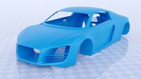
printable audi car
...printable audi car
3dexport
printable audi car
turbosquid
$40

Fox printable
...lty free 3d model fox printable for download as blend and stl on turbosquid: 3d models for games, architecture, videos. (1507558)
turbosquid
$23

Printable Statue
...ty free 3d model printable statue for download as obj and stl on turbosquid: 3d models for games, architecture, videos. (1415137)
turbosquid
$3

Ear Printable
...yalty free 3d model ear printable for download as obj and stl on turbosquid: 3d models for games, architecture, videos. (1671689)
turbosquid
$1

heart printable
...y free 3d model heart printable for download as stl and sldpr on turbosquid: 3d models for games, architecture, videos. (1209566)
turbosquid
$1
Printable Hook
...
royalty free 3d model 3d printable hook for download as stl on turbosquid: 3d models for games, architecture, videos. (1413683)
turbosquid
$30
Printable support
... model 3d printable support for download as max, 3ds, and stl on turbosquid: 3d models for games, architecture, videos. (1689342)
turbosquid
$24

Printable Dolphin
...el printable dolphin for download as , dae, fbx, obj, and stl on turbosquid: 3d models for games, architecture, videos. (1602353)
Space
3ddd
free
Space
... space , вытяжка
вытяжка elica space, производство elica evolution
3d_ocean
$19

Space station
...space station
3docean
space station
space station
3d_ocean
$7
Space Fighter
...space fighter
3docean
fighter space
space fighter
turbosquid
$5
space
...e
turbosquid
royalty free 3d model space for download as max on turbosquid: 3d models for games, architecture, videos. (1184221)
turbosquid
$2

Space
...turbosquid
royalty free 3d model space for download as blend on turbosquid: 3d models for games, architecture, videos. (1660625)
3d_ocean
$4
Space Station
...space station
3docean
habitat low poly ship space space ship space station vehicle
space station low poly modelled, not textured.
turbosquid
$2

Space
...royalty free 3d model space for download as max, fbx, and obj on turbosquid: 3d models for games, architecture, videos. (1644726)
turbosquid
$8

Space
...ty free 3d model space for download as c4d, 3ds, fbx, and obj on turbosquid: 3d models for games, architecture, videos. (1521166)
turbosquid
$160

space
... available on turbo squid, the world's leading provider of digital 3d models for visualization, films, television, and games.
turbosquid
$5

Space
... available on turbo squid, the world's leading provider of digital 3d models for visualization, films, television, and games.