Thingiverse
Curta Calculator Mods by mcmaven
by Thingiverse
Last crawled date: 3 years ago
I made a number of design modifications that I felt better supported 3D printing and the use of plastic vs. metal components.
3/28/19
Added case/container files.
Tens Sliders
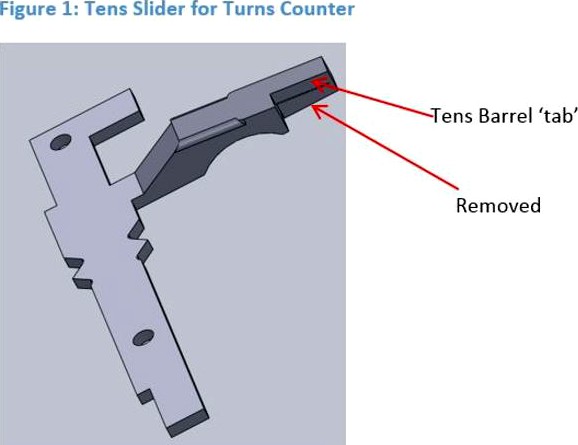
I believe that Mr. Wu’s STLs for the Tens Sliders were based on models of the original metal versions of the components. I had trouble with my 3D printed sliders because the arms that engaged the Tens Barrel were too fragile and too flexible.
I redesigned them so I didn’t need to enable supports for the parts, and made them stiffer. Also I added a fillet to the surface that engaged the transmission gear teeth so they were less likely to snag on the edge. After the print is complete, I used some dykes to snap off the support for the ‘tab’ that engaged the Tens Barrel.
Figure 1: Tens Slider for Turns Counter
I suspect that the holes in the sliders are an artifact from the original metal design. I couldn’t see any obvious use for them.
Figure 2: Tens Slider for Results
I also modified the Tens Slide Bearing to allow a little more room for the Sliders to move, and to position them vertically more accurately. I know the bolt holds them in place, but I found it made life easier when was fitting them. I ended up inserting and removing the slider assembly several times to adjust the spring to hold them in the correct position when the transmission gear was engaged and disengaged. There are a lot of them, and bolting them down every time was a pain. Now they snap in and don’t slide up and down without the bolt. However you still need the bolt to keep them from working out their way out of the slot over time.
9,10,11 digits transmission shafts
I had problems with these 3 transmission shafts in particular. I used the Lock Tight to hold the gears in place as recommended, but I didn’t wait until the Lock Tight was completely dry before removing the gears. Don’t touch the shafts for at least 24 hours after apply the Lock Tight.
Removing the gears prematurely smeared the Lock Tight the length of the shaft, and caused the bearing surface at the bottom of the shaft to bind. And that stuff is HARD to get off. The gears don’t slide up and down these shaft, like on the digits shafts, but it took a lot of sanding just to get bearing surfaces of the shafts so they did not feel sticky anymore.
Also with these 3 shafts, the transmission gear is in the center of the shaft. I found that the shaft would bend out when I turned the Tens Barrel, and cause it to jam. If I held them in place when I turned the Tens Barrel, they worked fine. So I designed this ‘Carry Brace’ to keep them from flexing when the they engaged the Tens Barrel teeth.
Figure 3: Carry Brace
The two large cutouts go around the Frame Supports, and the 3 smaller ones keep the transmission shafts from flexing. I used dichloromethane (Acrylic Solvent) to glue it to the Frame Supports, just below the lower transmission gears.
Figure 4: Carry Brace Installed
I tried printing the spring_clip_for_transmission_gears STL, and discovered the reason that Mr. Wu suggested using Lock Tight. They didn’t even appear after slicing because they were so thin. I believe that this was another case of trying to render a plastic 3D part from a metal part design. As an alternative, I designed some heftier clips, which seem to work pretty well. They snap it to the groves on the transmission shafts and are thin enough not to interfere with the Tens Barrel teeth. See them below the transmission gears in the figure above. In some cases I filed them to get the transmission gear to better align vertically with the Tens Barrel teeth.
Clearing Ring
I decided that I wanted to make a case for the Curta like the original bakelite cases that came with them. To do this, I had to redesign the Clearing Ring so it could be folded in to the body. I had already printed the clearing_cover, and didn’t want to do it again, so my design can be retrofitted to the current clearing_cover design.
Figure 5: Clearing Ring
The Clearing Ring is only slightly modified. I added a curve to the top ‘Clearing Ring Pin’ slot, so the Clearing ring could pivot around the bottom ‘Pivot’. The top hole is the same diameter as the rivet holes in the clearing_cover. This allows the Clearing Ring Pin to lock the clearing_cover in place when it is released. To make this work I also redesigned the rivets.
Figure 6: Pivotable Clearing Ring
The Clearing Ring Pin fits in the clearing_cover hole on the left, and the Clearing Ring Pivot fits in the hole on the right. Through the hole in the Clearing Ring Pin I ran some piano wire to act as a spring to hold the pin up. It was a hack, but I drilled some holes in the clearing_cover and popped the wire into them. If I were to print the clearing_cover again, I would design a better method of holding the piano wire. Flexing the piano wire to get it to go in to the drilled holes, bent it, causing the pin to not sit as high as it could. But it seems to work fine. Press the pin, and the Clearing Ring pivots against the crank.
Figure 7: Clearing Ring Pin
I added a flat to the Clearing Ring ‘Pivot’ so the Clearing Ring could be removed if desired. This I just glued in place.
Figure 8: Clearing Ring Pivot
Zero Positioning Assembly
I found the zero_positioning_lever would bind, and the roller was low enough to ride against the anti-rotation teeth of the zero_positioning_disc, rather than seating properly in the zero position notch. Also, given the zero_positioning lever and roller design, it wasn’t clear to me how to attach the roller to the lever.
I modified the zero_positioning_lever to have a longer shaft to hold the roller 1mm higher, so that the roller would only engage the zero position notch (not the anti-rotation teeth). I then modified the zero_positioning_lever_bolt_sleeve to handle the longer zero_positioning_lever shaft, and added some more length to it to ensure that the zero_positioning_lever would not bind.
Finally I made the zero_positioning_roller a little thinner, and the hole in it larger to accommodate a zero_positioning_roller_bolt_sleeve that I designed. This allowed a 5Mx10 bolt to be used to hold the roller in place.
Figure 9: Zero Positioning Lever Assembly
Reversing Shaft
I couldn’t get a 5M nut to stay on the reversing_shaft because there was just not enough plastic to cut a good thread. So I increased the radius of the treaded area to 4.8mm.
Bottom Cover
I printed the bottom cover with a 98 mm hole in it. This is very useful if it jams and you need to release the anti-reverse pawl. It also makes it much easier to hold with one hand.
To Support or Not Support
On my printer, any surface that sits on top of support material is ugly. I tried reducing the gap between the support material to .1 mm, but the surfaces still required a lot of clean up. Less than .1mm, the support material would not come off.
I also didn’t use any skirts.
As an experiment to minimize my need for using supports, I used meshmixer to split components into multiple parts, where each sub-component didn’t need support, and glued them together later. Depending on your printer, you may not want to go to these extents to avoid using supports.
I used this technique on the bearing plate, Step_Drum, zero_positioning_disk, main_crank, upper_housing, lower_housing, selector_knobs, tens_bell_spring, Reversing_Lever, results_dials, selector_shaft_top, and virtually all the shafts, i.e. the main_shaft, reversing_shaft, the transmission shafts, number_roll_carry pins, etc.
In most cases, the files that I generated for the split componets use same prefix, and a numeric suffix to indicate the stacking order. The Step_Drum files are an exception.
For the Step_Drum, I used the models from OnShape to group the various results_segments into small stacks that could be printed without supports. Each stack I had to sand down a little so they would have the correct spacing. Each results_segment was 1.5mm thick, so determining the heights of the various segment groups was straight forward.
The Step Drum Lower Segment STL file name suffixes indicate the number of teeth of the segment. Looking at Figure 10 the file order from top to bottom is:
Step Drum Termination Segment.STL
Step Drum Lower Segment 1-9.STL
Step Drum Lower Segment 2-8.STL
Step Drum Lower Segment 3-7.STL
Step Drum Lower Segment 4-6.STL
Step Drum Lower Segment 5-6.STL
Step Drum Lower Segment 4-7.STL
Step Drum Lower Segment 3-8.STL
Step Drum Lower Segment 2-9.STL
Step Drum Lower Segment 1-10.STL
Step Drum Frame Bottom.STL
I only used supports for the crank_collar, clearing_cover, main_body, tens_slide_bearing, tens_bell, and transmission gears.
The Case
Warning: For the case I used 2 1KG spools of filament (because I didn’t want to run out in the middle of print) and it took almost 75 hours to print. So it’s a commitment.
The Container bottom is a single file, Container Bottom.STL (35.5 Hrs).
Again, to reduce the support material requirements, the Container Top consists of 3 files.
Container Top 1.STL (8.5 Hrs) is the dome on the top. Container Top 2.STL (31.5 Hrs) is the cylinder part of the top. And the Container Top Spacer.STL presses against the Main Crank to prevent the calculator from moving in the case. I just carefully glued these together. Unless you know it’s there, you can’t see the seam between the Top 1 and 2 pieces.
The base layer of the Container Bottom lifted off the print plate a little on one side (sort of a crescent moon shape). I didn’t notice this until the print was complete. It only left a tiny artifact around the bottom of the base (that most people don’t notice), so I didn’t bother to try printing it again. But in looking up possible solutions for the problem, I fixated on the possibility that a large flat part (e.g. > 6 inches in diameter) can cool/contract at different rates and cause the base layer to break away. My solution to this was to reduce the contact area when I printer the Container Top 1.STL. If you look at the STL you will see concentric rings on the bottom. The every other ring is recessed 0.1mm. This seemed to do the trick, because the top didn’t lift at all.
The case is designed to support the use of ¼ in foam to act as padding on the bottom of the case, and on the bottom of the spacer (between it and the Main Crank). I used a high density which looks nice, but has too much memory. I designed the cover’s screw clamp mechanism based on what I could see from some low res photos that I found on the web. My design doesn’t provide a positive locking mechanism (e.g. plastic locking bumps) to hole the top on. It didn’t seem to make a difference at first because the foam put enough pressure on the connection to prevent the top from easily unscrewing. But after a couple weeks the foam had compressed, so a little bump caused the top to unscrew. So use better foam, or redesign the screw mechanism. After I got my design done, I got to look at an original Curta case, which used longer overlapping threads, and an O-ring to seal the case and to provide the pressure needed to keep it from unscrewing.
Other Stuff
• I tapered the ends of all the digit transmission gears that slide with a file so they would be less likely to snag a Step Drum tooth, when moved. I also filed out between the teeth for the same reason.
• I have a lathe, which I used liberally to clean up parts, and trim transmission shafts so the gears slid smoothly. I made a jig to hold the results_dials, and turned them and the selector_shaft_tops, to put a smooth surface on them for the lettering.
• Screwing the digits_cover to the upper_housing was a pain. I had put the digit lettering on the bottom of the upper_housing when I realized that it wasn’t tight, so now the digits don’t line up with the arrows.
• I bought a Silhouette Cameo 3 to do the lettering, and overall I’d say that it is a great little product. Within an hour of taking it out of the box, I had my initial stencils. It has no problem with the fine resolution of the small (5mm) characters. Their business model tries to suck you into a monthly subscription to get access to models/patterns, but the base software that it comes with will let you generate tool paths from jpg’s, jiff’s, and other formats.
• For some reason, reading the DXF files in to any program I had resulted in some or all of the characters being garbage (Figure 11). This is what 5mm_digits.dfx looked like when I imported it in 3 different programs, including the Silhouette software. Not pretty… And the other DFX files were distorted in other ways that made them unusable.
Mr. Wu had used QCAD to generate the DXF files. I downloaded it, and used it to export the DXFs as (ancient) R9 versions. These versions of the files imported correctly into the Silhouette software, but the problem was that they were stretched to full 12 in width of the vinyl cutter. I then had to resize them to fit the plastic.
• There is no alignment hole in the main_shaft STL file for the step_drum_frame_bottom, but there is a hole for a pin to fix the main shaft in the step_drum_frame_bottom model. When I drilled the hole, I was off by a couple of degrees. So I shortened the length of the zero_positioning_lever arm about 3 mm to compensate. Everything seems to be working, but need to go back and fix this correctly.
• I was lazy and applied the vinyl lettering directly everywhere, rather than using them as stencils and painting them on. Only two results dial digits have been rubbed off, but the only viable long term solution is to paint them on, as Mr. Wu has recommended.
Update 10/3/18
I generated the case artwork (Container Label) using the program that came with the Silhouette vinyl cutter. The Silhouette software is pretty limited in its export capability. So the 'Container Label.studio3' is the native format, and gsp is the only other format that it supports. I also captured screen shots in jpg and png, if that helps.
I took it to a local maker fair, and it took a beating after several hours of little kids cranking it. One of the selector shaft bearings broke, so I lost a digit, but then something else broke, and it stopped working all together. I have to tear it apart and find out what went wrong.
3/28/19
Added case/container files.
Tens Sliders
I believe that Mr. Wu’s STLs for the Tens Sliders were based on models of the original metal versions of the components. I had trouble with my 3D printed sliders because the arms that engaged the Tens Barrel were too fragile and too flexible.
I redesigned them so I didn’t need to enable supports for the parts, and made them stiffer. Also I added a fillet to the surface that engaged the transmission gear teeth so they were less likely to snag on the edge. After the print is complete, I used some dykes to snap off the support for the ‘tab’ that engaged the Tens Barrel.
Figure 1: Tens Slider for Turns Counter
I suspect that the holes in the sliders are an artifact from the original metal design. I couldn’t see any obvious use for them.
Figure 2: Tens Slider for Results
I also modified the Tens Slide Bearing to allow a little more room for the Sliders to move, and to position them vertically more accurately. I know the bolt holds them in place, but I found it made life easier when was fitting them. I ended up inserting and removing the slider assembly several times to adjust the spring to hold them in the correct position when the transmission gear was engaged and disengaged. There are a lot of them, and bolting them down every time was a pain. Now they snap in and don’t slide up and down without the bolt. However you still need the bolt to keep them from working out their way out of the slot over time.
9,10,11 digits transmission shafts
I had problems with these 3 transmission shafts in particular. I used the Lock Tight to hold the gears in place as recommended, but I didn’t wait until the Lock Tight was completely dry before removing the gears. Don’t touch the shafts for at least 24 hours after apply the Lock Tight.
Removing the gears prematurely smeared the Lock Tight the length of the shaft, and caused the bearing surface at the bottom of the shaft to bind. And that stuff is HARD to get off. The gears don’t slide up and down these shaft, like on the digits shafts, but it took a lot of sanding just to get bearing surfaces of the shafts so they did not feel sticky anymore.
Also with these 3 shafts, the transmission gear is in the center of the shaft. I found that the shaft would bend out when I turned the Tens Barrel, and cause it to jam. If I held them in place when I turned the Tens Barrel, they worked fine. So I designed this ‘Carry Brace’ to keep them from flexing when the they engaged the Tens Barrel teeth.
Figure 3: Carry Brace
The two large cutouts go around the Frame Supports, and the 3 smaller ones keep the transmission shafts from flexing. I used dichloromethane (Acrylic Solvent) to glue it to the Frame Supports, just below the lower transmission gears.
Figure 4: Carry Brace Installed
I tried printing the spring_clip_for_transmission_gears STL, and discovered the reason that Mr. Wu suggested using Lock Tight. They didn’t even appear after slicing because they were so thin. I believe that this was another case of trying to render a plastic 3D part from a metal part design. As an alternative, I designed some heftier clips, which seem to work pretty well. They snap it to the groves on the transmission shafts and are thin enough not to interfere with the Tens Barrel teeth. See them below the transmission gears in the figure above. In some cases I filed them to get the transmission gear to better align vertically with the Tens Barrel teeth.
Clearing Ring
I decided that I wanted to make a case for the Curta like the original bakelite cases that came with them. To do this, I had to redesign the Clearing Ring so it could be folded in to the body. I had already printed the clearing_cover, and didn’t want to do it again, so my design can be retrofitted to the current clearing_cover design.
Figure 5: Clearing Ring
The Clearing Ring is only slightly modified. I added a curve to the top ‘Clearing Ring Pin’ slot, so the Clearing ring could pivot around the bottom ‘Pivot’. The top hole is the same diameter as the rivet holes in the clearing_cover. This allows the Clearing Ring Pin to lock the clearing_cover in place when it is released. To make this work I also redesigned the rivets.
Figure 6: Pivotable Clearing Ring
The Clearing Ring Pin fits in the clearing_cover hole on the left, and the Clearing Ring Pivot fits in the hole on the right. Through the hole in the Clearing Ring Pin I ran some piano wire to act as a spring to hold the pin up. It was a hack, but I drilled some holes in the clearing_cover and popped the wire into them. If I were to print the clearing_cover again, I would design a better method of holding the piano wire. Flexing the piano wire to get it to go in to the drilled holes, bent it, causing the pin to not sit as high as it could. But it seems to work fine. Press the pin, and the Clearing Ring pivots against the crank.
Figure 7: Clearing Ring Pin
I added a flat to the Clearing Ring ‘Pivot’ so the Clearing Ring could be removed if desired. This I just glued in place.
Figure 8: Clearing Ring Pivot
Zero Positioning Assembly
I found the zero_positioning_lever would bind, and the roller was low enough to ride against the anti-rotation teeth of the zero_positioning_disc, rather than seating properly in the zero position notch. Also, given the zero_positioning lever and roller design, it wasn’t clear to me how to attach the roller to the lever.
I modified the zero_positioning_lever to have a longer shaft to hold the roller 1mm higher, so that the roller would only engage the zero position notch (not the anti-rotation teeth). I then modified the zero_positioning_lever_bolt_sleeve to handle the longer zero_positioning_lever shaft, and added some more length to it to ensure that the zero_positioning_lever would not bind.
Finally I made the zero_positioning_roller a little thinner, and the hole in it larger to accommodate a zero_positioning_roller_bolt_sleeve that I designed. This allowed a 5Mx10 bolt to be used to hold the roller in place.
Figure 9: Zero Positioning Lever Assembly
Reversing Shaft
I couldn’t get a 5M nut to stay on the reversing_shaft because there was just not enough plastic to cut a good thread. So I increased the radius of the treaded area to 4.8mm.
Bottom Cover
I printed the bottom cover with a 98 mm hole in it. This is very useful if it jams and you need to release the anti-reverse pawl. It also makes it much easier to hold with one hand.
To Support or Not Support
On my printer, any surface that sits on top of support material is ugly. I tried reducing the gap between the support material to .1 mm, but the surfaces still required a lot of clean up. Less than .1mm, the support material would not come off.
I also didn’t use any skirts.
As an experiment to minimize my need for using supports, I used meshmixer to split components into multiple parts, where each sub-component didn’t need support, and glued them together later. Depending on your printer, you may not want to go to these extents to avoid using supports.
I used this technique on the bearing plate, Step_Drum, zero_positioning_disk, main_crank, upper_housing, lower_housing, selector_knobs, tens_bell_spring, Reversing_Lever, results_dials, selector_shaft_top, and virtually all the shafts, i.e. the main_shaft, reversing_shaft, the transmission shafts, number_roll_carry pins, etc.
In most cases, the files that I generated for the split componets use same prefix, and a numeric suffix to indicate the stacking order. The Step_Drum files are an exception.
For the Step_Drum, I used the models from OnShape to group the various results_segments into small stacks that could be printed without supports. Each stack I had to sand down a little so they would have the correct spacing. Each results_segment was 1.5mm thick, so determining the heights of the various segment groups was straight forward.
The Step Drum Lower Segment STL file name suffixes indicate the number of teeth of the segment. Looking at Figure 10 the file order from top to bottom is:
Step Drum Termination Segment.STL
Step Drum Lower Segment 1-9.STL
Step Drum Lower Segment 2-8.STL
Step Drum Lower Segment 3-7.STL
Step Drum Lower Segment 4-6.STL
Step Drum Lower Segment 5-6.STL
Step Drum Lower Segment 4-7.STL
Step Drum Lower Segment 3-8.STL
Step Drum Lower Segment 2-9.STL
Step Drum Lower Segment 1-10.STL
Step Drum Frame Bottom.STL
I only used supports for the crank_collar, clearing_cover, main_body, tens_slide_bearing, tens_bell, and transmission gears.
The Case
Warning: For the case I used 2 1KG spools of filament (because I didn’t want to run out in the middle of print) and it took almost 75 hours to print. So it’s a commitment.
The Container bottom is a single file, Container Bottom.STL (35.5 Hrs).
Again, to reduce the support material requirements, the Container Top consists of 3 files.
Container Top 1.STL (8.5 Hrs) is the dome on the top. Container Top 2.STL (31.5 Hrs) is the cylinder part of the top. And the Container Top Spacer.STL presses against the Main Crank to prevent the calculator from moving in the case. I just carefully glued these together. Unless you know it’s there, you can’t see the seam between the Top 1 and 2 pieces.
The base layer of the Container Bottom lifted off the print plate a little on one side (sort of a crescent moon shape). I didn’t notice this until the print was complete. It only left a tiny artifact around the bottom of the base (that most people don’t notice), so I didn’t bother to try printing it again. But in looking up possible solutions for the problem, I fixated on the possibility that a large flat part (e.g. > 6 inches in diameter) can cool/contract at different rates and cause the base layer to break away. My solution to this was to reduce the contact area when I printer the Container Top 1.STL. If you look at the STL you will see concentric rings on the bottom. The every other ring is recessed 0.1mm. This seemed to do the trick, because the top didn’t lift at all.
The case is designed to support the use of ¼ in foam to act as padding on the bottom of the case, and on the bottom of the spacer (between it and the Main Crank). I used a high density which looks nice, but has too much memory. I designed the cover’s screw clamp mechanism based on what I could see from some low res photos that I found on the web. My design doesn’t provide a positive locking mechanism (e.g. plastic locking bumps) to hole the top on. It didn’t seem to make a difference at first because the foam put enough pressure on the connection to prevent the top from easily unscrewing. But after a couple weeks the foam had compressed, so a little bump caused the top to unscrew. So use better foam, or redesign the screw mechanism. After I got my design done, I got to look at an original Curta case, which used longer overlapping threads, and an O-ring to seal the case and to provide the pressure needed to keep it from unscrewing.
Other Stuff
• I tapered the ends of all the digit transmission gears that slide with a file so they would be less likely to snag a Step Drum tooth, when moved. I also filed out between the teeth for the same reason.
• I have a lathe, which I used liberally to clean up parts, and trim transmission shafts so the gears slid smoothly. I made a jig to hold the results_dials, and turned them and the selector_shaft_tops, to put a smooth surface on them for the lettering.
• Screwing the digits_cover to the upper_housing was a pain. I had put the digit lettering on the bottom of the upper_housing when I realized that it wasn’t tight, so now the digits don’t line up with the arrows.
• I bought a Silhouette Cameo 3 to do the lettering, and overall I’d say that it is a great little product. Within an hour of taking it out of the box, I had my initial stencils. It has no problem with the fine resolution of the small (5mm) characters. Their business model tries to suck you into a monthly subscription to get access to models/patterns, but the base software that it comes with will let you generate tool paths from jpg’s, jiff’s, and other formats.
• For some reason, reading the DXF files in to any program I had resulted in some or all of the characters being garbage (Figure 11). This is what 5mm_digits.dfx looked like when I imported it in 3 different programs, including the Silhouette software. Not pretty… And the other DFX files were distorted in other ways that made them unusable.
Mr. Wu had used QCAD to generate the DXF files. I downloaded it, and used it to export the DXFs as (ancient) R9 versions. These versions of the files imported correctly into the Silhouette software, but the problem was that they were stretched to full 12 in width of the vinyl cutter. I then had to resize them to fit the plastic.
• There is no alignment hole in the main_shaft STL file for the step_drum_frame_bottom, but there is a hole for a pin to fix the main shaft in the step_drum_frame_bottom model. When I drilled the hole, I was off by a couple of degrees. So I shortened the length of the zero_positioning_lever arm about 3 mm to compensate. Everything seems to be working, but need to go back and fix this correctly.
• I was lazy and applied the vinyl lettering directly everywhere, rather than using them as stencils and painting them on. Only two results dial digits have been rubbed off, but the only viable long term solution is to paint them on, as Mr. Wu has recommended.
Update 10/3/18
I generated the case artwork (Container Label) using the program that came with the Silhouette vinyl cutter. The Silhouette software is pretty limited in its export capability. So the 'Container Label.studio3' is the native format, and gsp is the only other format that it supports. I also captured screen shots in jpg and png, if that helps.
I took it to a local maker fair, and it took a beating after several hours of little kids cranking it. One of the selector shaft bearings broke, so I lost a digit, but then something else broke, and it stopped working all together. I have to tear it apart and find out what went wrong.
Similar models
thingiverse
free

lower ring bracket by bobbyshomerul
...ned a bracket to link it to the big gear.
you need to print 4 pcs and glue them to big gear and use upperring instead of lowering
thingiverse
free

Simple Centrifugal Puzzlebox by tarheel365
...er than they need to be because i had designed them around some screws i had, which didn't fit so i just 3d printed the pins.
thingiverse
free

Raspberry Pi3 B case refurbished by Viciente
...neither did help. so i additionally split the case top with the inside mounting of the fan in two pieces - to glue them together.
thingiverse
free

Walkera G-2D Gimbal to DJI Phantom 1 and F40 by Droneme
... print. i included a top part with and without supports.
added another version part to allow mounting to phantom 2 (6,16,2015)
thingiverse
free

CellMeter 8 charging station
...
upper case: supports for the bottom overhangs (leave windows unsupported)
light support: support only needed for bottom overhang
thingiverse
free

V2_arduino case, unten offen by juewei
... the nano's had their pin headers soldered at the bottom.
so here is a redesign of the bottom half with appropriate openings.
thingiverse
free

Medicine Cup/Shot Glass Holder/Display by Druha
...h but the uploaded models have no text. overall not a very complicated model and shouldn't require that much support, if any.
thingiverse
free

Hubsan CG/landing Pad by air2gnd
...es are pilot. previous inner ring had top heavy problems. i had 4 additional lower holes so weights can be added to lower the cg.
thingiverse
free

stm32f4-discovery box by BogdanKecman
...a solder there hitting them
on top piece i had to move the otg and audio holes 1.4mm to the side to properly align with the board
thingiverse
free

Polisher Machine
...nd made some holes for the power connector the switch and the wiring.
the bearing is 608 zz or abec 7 standard skate board gears.
Mcmaven
thingiverse
free

Mazda Rx7 Wankel Remix by mcmaven
...y only concern is that i might have lost some brain cells using so much superglue... make sure you have good ventilation!
mcmaven
thingiverse
free

Triaxial Motorized (Updated Arduino Code & Split Clock face for smaller printers) by jnash123
...for smaller printers) by jnash123 thingiverse brilliant design from mcmaven - thank you so much for sharing! just recently...
grabcad
free

Gyrotourbillon
...gyrotourbillon grabcad model design by mcmaven ...
grabcad
free

TT Furious Tourbillon
...tt furious tourbillon grabcad model design by mcmaven ...
grabcad
free

Triple Axis Tourbillon
...triple axis tourbillon grabcad model design by mcmaven ...
grabcad
free

Mazda Rx7 Wankel Remix
...mazda rx7 wankel remix grabcad model design by mcmaven /...
grabcad
free

Flat Head V8 Desktop Stand
...flat head v8 desktop stand grabcad model design by mcmaven /...
Curta
turbosquid
$1

Espada curta
...rbosquid
royalty free 3d model espada curta for download as on turbosquid: 3d models for games, architecture, videos. (1639209)
thingiverse
free

Handle for a Curta calculator by bholz
...a m3 screw and 2 washers to make it rotating on the handle.
the handle is fixed with the original tiny bolt onto the curtas axis.
thingiverse
free

Curta type 2 step drum by Mads_Eskildsen
...ed that in inventor i accidently put all the cm and mm dimensions as inches, i am not sure if these dimensions carry over to stl.
thingiverse
free

Curta Type I Case
... these print times are only mentioned as guidelines, your print times could vary depending on your printer and filament settings.
thingiverse
free

curta calculator type 1 1:3 multimaterial parts by DontTakeMyUsername
...s came assembledhttps://www.thingiverse.com/thing:3178684.
i hope this will makes the build process of the curta a bit more easy.
thingiverse
free

Curta Calculator Type I scaled at 3:1 by mwu
... height, infill, orientation, and support notes to the printed files in the bom. first step in getting actual build instructions.
thingiverse
free

Curta tens lever slider bearing (with spring) by gilly914
...f1044ccccd93f4d45c33c88f/w/8d0edb316652098105d1c527/e/121fb714e5f87f00de2dff73
(first time using onshape, so my work is sub-par.)
thingiverse
free

Dials with Debossed Numbers for Curta Calculator Type I scaled at 3:1 by RestoredOlive
...roove. make sure you sand the dials well before trying this, because the paint can easily get stuck in small print imperfections.
thingiverse
free

Curta Calculator Multimaterial Parts
..., 2019: initial publish of stls and (3/a)mf plates.
nov 17,2019: added the inner lower housing (and separate outer lower housing)
Calculator
archibase_planet
free

Calculator
...et
calculator pocket calculator office equipment
calculator n220514 - 3d model (*.gsm+*.3ds+*.max) for interior 3d visualization.
3d_export
free

calculator
...calculator
3dexport
calculator .fbx .max
3d_ocean
$6

Calculator
...ted in cinema 4d with vray. all needed materials and images included in the download file. also there is two format included (...
turbosquid
$3

calculator
...bosquid
royalty free 3d model calculator for download as fbx on turbosquid: 3d models for games, architecture, videos. (1219363)
turbosquid
$2

Calculator
...bosquid
royalty free 3d model calculator for download as fbx on turbosquid: 3d models for games, architecture, videos. (1297953)
turbosquid
free

calculator
...bosquid
royalty free 3d model calculator for download as max on turbosquid: 3d models for games, architecture, videos. (1640253)
turbosquid
$5

Calculator
...
royalty free 3d model pocket calculator for download as c4d on turbosquid: 3d models for games, architecture, videos. (1542343)
turbosquid
$1

Calculator
...
royalty free 3d model calculator for download as max and fbx on turbosquid: 3d models for games, architecture, videos. (1301935)
3d_export
$5

calculator
...calculator
3dexport
3d_export
free

calculator
...calculator
3dexport
Mods
design_connected
$13

MOD. 4233 - MOD. 4234 Table Lamp
...mod. 4233 - mod. 4234 table lamp
designconnected
arcahorn mod. 4233 - mod. 4234 table lamp computer generated 3d model.
design_connected
$11

MOD.1095
...mod.1095
designconnected
mod.1095 computer generated 3d model. designed by sarfatti, gino.
3ddd
$1

fireplaces mod Spec
...fireplaces mod spec
3ddd
камин
fireplaces mod spec 180x90x125h
3ddd
free

Flos Mod. 2129
... mod
фабрика: flos
модель: mod. 2129
описание: подвесной светильник, металл, белый, черный.
сайт: www.flos.com
turbosquid
$32
MOD A 001
... available on turbo squid, the world's leading provider of digital 3d models for visualization, films, television, and games.
turbosquid
$29
Maars Mod
... available on turbo squid, the world's leading provider of digital 3d models for visualization, films, television, and games.
turbosquid
$15
Mod 70..
... available on turbo squid, the world's leading provider of digital 3d models for visualization, films, television, and games.
turbosquid
$10

MOD Sofa
... available on turbo squid, the world's leading provider of digital 3d models for visualization, films, television, and games.
turbosquid
$1

Mod-Lite
... available on turbo squid, the world's leading provider of digital 3d models for visualization, films, television, and games.
turbosquid
$1
pc mod
... available on turbo squid, the world's leading provider of digital 3d models for visualization, films, television, and games.