Thingiverse
Arduino LED powered Hello World Sign by alfredosequeida
by Thingiverse
Last crawled date: 3 years ago
You can find all of the code required on my GitHub
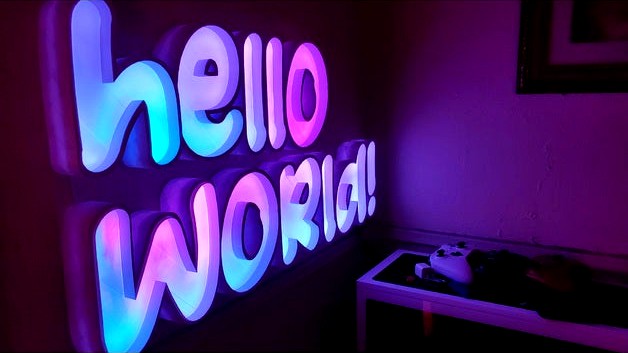
This is a 3d printed "hello world!" sign powered by the L0L1n/NodeMCU V3 board, which hosts the ESP8266E board. All of the code, schematics, openSCAD (3D model), and mechanical drawings for the project are open-source for you to modify however you want.
The model
The model for this design was made using openSCAD. Each letter is meant to be printed individually and then glued together. Because of this, each letter has been split into a module in the openSCAD code. Each letter is between 59.9mm and 205.10mm in length, 184.10mm and 193.3mm in width and 50mm in height in horizontal (laying down) orientation. This model was built with the thought in mind of mounting the letters on a wall, which is why 4 of the letters ("h", "o1", "w", "!", where a letter followed by an integer defines the letter in position to the whole phrase "hello world". Making "o1" the first "o" in "hello") have holes for a screw or nail. With that said, with the letters mounted on the wall split into two rows of the words "hello" and "world!", this entire sign measures a maximum of 790.5mm X 384.2mm X 50 mm (l X w X h) with the letters standing up mounted on a wall.
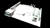
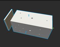
Every model also has an insert, which is a very thin copy of the letter with half the laying down height which serves as both a cover and a light defuser for the LEDs:
The inserts fit snug into the letters with a 0.5mm gap, however, you might want to use some sandpaper or a file to create a little more room for letters like the "e", "o", and "d", which have center cutouts since those parts might be a bit more difficult to fit easily.
Modifying the model
If you want to change the size of the model, this can easily be achieved by changing the attributes at the top of the openSCAD code. All of the measurements are unitless, but mm should be used as those are the units used to measure the electrical components.
font_size: The size of the font.
height: The height/depth of the model laying down +10mm, so 40mm makes the depth 50mm.
wall: The thickness of the walls -5mm, so 10mm makes the walls 5mm thick.
If the size is adjusted, the position of the LED pass through-holes should be modified as well. The same applies to the horizontal and vertical positions of the letters (h_x, w_y, etc).
The strange adding and subtracting of magical numbers in the measurements is due to the way the walls were created with openSCAD'S Minkowski method.
Printing the model
In the build for the video, this model was printed using a Creality Ender3 V2 with an extruder temperature of 225°C and base temperature of 70°C. Using 5% infill with a wall height of 0.28mm using white Inland PLA+. Each Letter took a maximum of 20 hours to print (the "w" took the longest time) and each insert took about 3 hours to print.
The Parts used
The following parts (electrical components) were used for this build:
(2) WS2812B LED Strip 5m 60leds/m
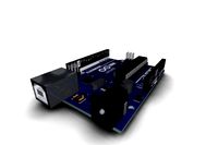
(1) LOL1n/NodeMCU V3 (ESP8266E) board
(1) LM2596S DC-DC 3A Buck Adjustable Step-down Power Supply Converter Module Used to step down the voltage to 5V if using a power supply larger than 5V.
(1) DC Female adapter
(1) 300 - 500 ohm resistor or combination of resistors to make the needed sum To protect the first LED when controlling the strip.
Wire, soldering iron, solder, shrink tube, and connectors to put everything together. With the exception of the wiring, the other parts are optional but recommended.
Included in the assets directory are SVG schematics for putting the parts together and mechanical drawings for the parts. Since they are SVG files, you can open them using a vector editing program like inkscape or a modern web browser and zoom in very close without losing detail.
The software
The software is controlled via the web interface hosted by the server on the ESP8266 board. To get the software on the board, it needs to be compiled and uploaded to the board using the Arduino IDE or arduino-cli. To do this, you must install the ESP8266 core for Arduino and these other dependencies not included with the ESP8266 core:
ArduinoJson: Used for handling the data sent via HTTP from the web application.
FastLED : Used to control the LED strip.
The code should also be modified using your local network's (WiFi) AP name and password. This can be set by modifying the character pointers const char* ssid and const char* password.
Then the LEDs can be controlled using the web interface accessible using a web browser using the IP address of the ESP8266 board after it has been connected to your network.
The web interface
The web interface is how you can control the LED colors, gradients, and animations of the LEDs. The interface is pretty self-explanatory, however, some of the logic behind it might be useful to explain for modification purposes. All of the HTML, CSS, and JavaScript for the web app can be found in the index.h file.
The gradients used for the lights are dynamically created at run time and are made using the CSS linear-gradient() function. This makes it easy to create gradients using CSS instead of using FastLED's method for creating gradients. The conversion to something FastLED can understand is handled using JavaScript and then sent over an HTTP POST request to the server as a JSON object with the following format to the /set-gradient-color endpoint.
{
"gradient":[
[
0,
255,
0,
0
],
[
255,
0,
0,
255
]
],
"brightness":255,
"animated":true
}
gradient: Array of arrays containing FastLED formatted gradient.
brightness : Integer containing FastLED formatter brightness value.
animated: Boolean value declaring if the gradient should be animated or not.
Thank you to Simon R. for his open-source project pickr, which provides the color picker for the web app.
Other notes
The wiring can be made a lot cleaner by rerouting the DC power input to the "W", where all of the electronic components are mounted. However, for my purposes, the exclamation point made a better location for the power input.
You can also use other LED strips, however, the software will need to be modified, and the chipset must be supported by FastLED. Note that the LEDs used in this project were used because they are individually addressable meaning that each LED can be controlled independently of the others, making it possible to create moving animations and gradients with the LEDs.
The font used for the model is Nooble Wooble
DISCLAIMER: Links included might be affiliate links. If you purchase a product with the links that I provide, I may receive a small commission. There is no additional charge to you!
This is a 3d printed "hello world!" sign powered by the L0L1n/NodeMCU V3 board, which hosts the ESP8266E board. All of the code, schematics, openSCAD (3D model), and mechanical drawings for the project are open-source for you to modify however you want.
The model
The model for this design was made using openSCAD. Each letter is meant to be printed individually and then glued together. Because of this, each letter has been split into a module in the openSCAD code. Each letter is between 59.9mm and 205.10mm in length, 184.10mm and 193.3mm in width and 50mm in height in horizontal (laying down) orientation. This model was built with the thought in mind of mounting the letters on a wall, which is why 4 of the letters ("h", "o1", "w", "!", where a letter followed by an integer defines the letter in position to the whole phrase "hello world". Making "o1" the first "o" in "hello") have holes for a screw or nail. With that said, with the letters mounted on the wall split into two rows of the words "hello" and "world!", this entire sign measures a maximum of 790.5mm X 384.2mm X 50 mm (l X w X h) with the letters standing up mounted on a wall.
Every model also has an insert, which is a very thin copy of the letter with half the laying down height which serves as both a cover and a light defuser for the LEDs:
The inserts fit snug into the letters with a 0.5mm gap, however, you might want to use some sandpaper or a file to create a little more room for letters like the "e", "o", and "d", which have center cutouts since those parts might be a bit more difficult to fit easily.
Modifying the model
If you want to change the size of the model, this can easily be achieved by changing the attributes at the top of the openSCAD code. All of the measurements are unitless, but mm should be used as those are the units used to measure the electrical components.
font_size: The size of the font.
height: The height/depth of the model laying down +10mm, so 40mm makes the depth 50mm.
wall: The thickness of the walls -5mm, so 10mm makes the walls 5mm thick.
If the size is adjusted, the position of the LED pass through-holes should be modified as well. The same applies to the horizontal and vertical positions of the letters (h_x, w_y, etc).
The strange adding and subtracting of magical numbers in the measurements is due to the way the walls were created with openSCAD'S Minkowski method.
Printing the model
In the build for the video, this model was printed using a Creality Ender3 V2 with an extruder temperature of 225°C and base temperature of 70°C. Using 5% infill with a wall height of 0.28mm using white Inland PLA+. Each Letter took a maximum of 20 hours to print (the "w" took the longest time) and each insert took about 3 hours to print.
The Parts used
The following parts (electrical components) were used for this build:
(2) WS2812B LED Strip 5m 60leds/m
(1) LOL1n/NodeMCU V3 (ESP8266E) board
(1) LM2596S DC-DC 3A Buck Adjustable Step-down Power Supply Converter Module Used to step down the voltage to 5V if using a power supply larger than 5V.
(1) DC Female adapter
(1) 300 - 500 ohm resistor or combination of resistors to make the needed sum To protect the first LED when controlling the strip.
Wire, soldering iron, solder, shrink tube, and connectors to put everything together. With the exception of the wiring, the other parts are optional but recommended.
Included in the assets directory are SVG schematics for putting the parts together and mechanical drawings for the parts. Since they are SVG files, you can open them using a vector editing program like inkscape or a modern web browser and zoom in very close without losing detail.
The software
The software is controlled via the web interface hosted by the server on the ESP8266 board. To get the software on the board, it needs to be compiled and uploaded to the board using the Arduino IDE or arduino-cli. To do this, you must install the ESP8266 core for Arduino and these other dependencies not included with the ESP8266 core:
ArduinoJson: Used for handling the data sent via HTTP from the web application.
FastLED : Used to control the LED strip.
The code should also be modified using your local network's (WiFi) AP name and password. This can be set by modifying the character pointers const char* ssid and const char* password.
Then the LEDs can be controlled using the web interface accessible using a web browser using the IP address of the ESP8266 board after it has been connected to your network.
The web interface
The web interface is how you can control the LED colors, gradients, and animations of the LEDs. The interface is pretty self-explanatory, however, some of the logic behind it might be useful to explain for modification purposes. All of the HTML, CSS, and JavaScript for the web app can be found in the index.h file.
The gradients used for the lights are dynamically created at run time and are made using the CSS linear-gradient() function. This makes it easy to create gradients using CSS instead of using FastLED's method for creating gradients. The conversion to something FastLED can understand is handled using JavaScript and then sent over an HTTP POST request to the server as a JSON object with the following format to the /set-gradient-color endpoint.
{
"gradient":[
[
0,
255,
0,
0
],
[
255,
0,
0,
255
]
],
"brightness":255,
"animated":true
}
gradient: Array of arrays containing FastLED formatted gradient.
brightness : Integer containing FastLED formatter brightness value.
animated: Boolean value declaring if the gradient should be animated or not.
Thank you to Simon R. for his open-source project pickr, which provides the color picker for the web app.
Other notes
The wiring can be made a lot cleaner by rerouting the DC power input to the "W", where all of the electronic components are mounted. However, for my purposes, the exclamation point made a better location for the power input.
You can also use other LED strips, however, the software will need to be modified, and the chipset must be supported by FastLED. Note that the LEDs used in this project were used because they are individually addressable meaning that each LED can be controlled independently of the others, making it possible to create moving animations and gradients with the LEDs.
The font used for the model is Nooble Wooble
DISCLAIMER: Links included might be affiliate links. If you purchase a product with the links that I provide, I may receive a small commission. There is no additional charge to you!
Similar models
thingiverse
free

An ESP8266-12E Compatible Peristaltic Pump base by coogle
...thingiverse.com/thing:803035
the code is also available to power the esp8266 here:
https://github.com/thissmarthouse/coogle-doser
thingiverse
free

Christmas Tree Ornament (WiFi Controlled) by GosseAdema
...nd a wifi connection.
a full description and the arduino code can be found on: http://www.instructables.com/member/gosse%20adema/
thingiverse
free

DaftPunk Arduino LED Code by GTIspeeder
...hing stopping you also treating the 4x8 array of leds on each side of the helmet as a matrix.
rename the attached stl file to ino
thingiverse
free

Jellyfish lamp by schme16
...tl" is more for a toy.
the code is being refined at the moment, but will be posted asap!
video! https://youtu.be/0j0szyd9kqc
thingiverse
free

Double Fan Mount (for Sanguinololu board) by JavierIH
...ed a more readable openscad file. the old one was my personal "hello world" to openscad and it had a really dirty code.
thingiverse
free

Eclipse RGB LED Wall Lamp with Wi-Fi by jasoncoon
...controller assembly instructions: https://www.evilgeniuslabs.org/wifi-led-controller
https://www.youtube.com/watch?v=h9ahnioacgq
thingiverse
free

ESP8266 Neopixel Controller
... able to use even more neopixels
setup
detailed informations about setup, source code and api interfaces can be founds on github.
thingiverse
free

Arduino Nano V3 Enclosure with led hole by Jhead
...mbine-to-one-led-pulse/854753/30
board: https://www.tinytronics.nl/shop/nl/arduino/main-boards/nano-v3.0-compatible-losse-headers
thingiverse
free

ESP8266 Self Balancing Robot by Kunnuck
...e a kick, because the robot doesn't have speed encoders, if you have any suggestion for make this project better let me know.
thingiverse
free

Somfy remote shade controller by bonnette
...he port forwarding and i am able to raise and lower my shades from anywhere in the world.
i have been using this for 2 years now.
Arduino
turbosquid
$7
Arduino
...turbosquid
royalty free 3d model arduino for download as max on turbosquid: 3d models for games, architecture, videos. (1197165)
turbosquid
$3
Arduino
...turbosquid
royalty free 3d model arduino for download as c4d on turbosquid: 3d models for games, architecture, videos. (1305484)
3d_export
$5
arduino satellite
...rt
this model is the exact arduino based satellite model with some basic sensors and camera modules and also includes batteries.
turbosquid
$1
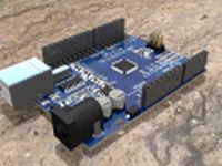
Arduino UNO
...alty free 3d model arduino uno for download as , stl, and wrl on turbosquid: 3d models for games, architecture, videos. (1515932)
3d_export
$5
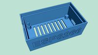
esp8266 box arduino
...esp8266 box arduino
3dexport
box for esp8266 module with wire hole. inside dimensions: 49x26 mm. height 15 mm.
3d_export
$60
Arduino Uno Rev3 Microcontroller 3D Model
...mega328p circuit board spark cable wire 5v 74v 9v 111v
arduino uno rev3 microcontroller 3d model danielgarnier4403 97237 3dexport
3d_export
free
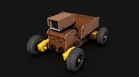
arduino rover kit
...no!!! materials: no!!! rigged: no animated: no uv mapped: no it is not an exact copy of the original! not subject to 3d printing!
3d_ocean
$7
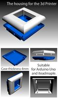
The housing for the 3d Printer
...the housing for the 3d printer 3docean arduino device housing stl the housing consists of two portions:...
3d_export
$5
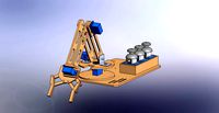
arm 4 axis
...uno -4 servo motor 180° -3 joystick (x,y) for arduino -mdf wood -some wires -cnc laser cut...
3d_export
$5
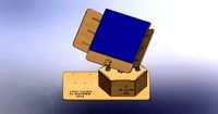
solar tracker
...machine for the frame . list of material : -arduino uno -2 step motor with driver -4 ldr sensor...
Hello
3ddd
$1

Кресло Hello
...кресло hello
3ddd
hello
кресло hello
3ddd
$1

Hello Kitty
...hello kitty
3ddd
hello kitty , кошка
мягкая игрушка hello kitty tartan + брелок
turbosquid
free

Hello
... available on turbo squid, the world's leading provider of digital 3d models for visualization, films, television, and games.
3ddd
$1

softline hello
...line
фабрика: softline
модель: hello
саит:http://www.softline.dk/en/products/chairs/hello.htm
--
turbosmooth не свернут
3ddd
$1

Hello Kitty
...hello kitty
3ddd
детская , hello kitty
настольная лампа - ночник в детскую комнату.
3ddd
$1

Кресло Hello
... softline , soft line
внутри архива копии fbx и obj
3ddd
free

кресло Hello
...проектировано дизайнерами busk+hertzog в качестве специального подарка для кайли миноуг от компании danish broadcast cooperation.
3ddd
free

hello kitty
...hello kitty
3ddd
hello kitty
подвесной шкаф в ванную с зеркалом. материалы и текстуры vray
3ddd
$1

Набор Hello Kitty
... набор , настольные принадлежности
настольные принадлежности для детской, hello kitty.
turbosquid
$7

hello bath
... available on turbo squid, the world's leading provider of digital 3d models for visualization, films, television, and games.
Sign
archibase_planet
free

Sign
...sign
archibase planet
signboard sign mask
restroom sign - 3d model for interior 3d visualization.
turbosquid
$1

Street Signs Stop Sign
...alty free 3d model street signs stop sign for download as fbx on turbosquid: 3d models for games, architecture, videos. (1672592)
turbosquid
free

Signs for the zodiac signs pack
...signs pack for download as 3ds, obj, wrl, fbx, stl, and sldpr on turbosquid: 3d models for games, architecture, videos. (1194807)
3d_ocean
$9

Road Signs
...road signs
3docean
outdoor road signs signpost waymark
road signs 3d models.
3d_export
$5

Biohazard sign
...biohazard sign
3dexport
biohazard sign
3ddd
$1

SUBWAY SIGN
...subway sign
3ddd
subway sign
3d_export
$5

road sign
...road sign
3dexport
road sign with the texture of a cyclist.
turbosquid
$45

Sign
... available on turbo squid, the world's leading provider of digital 3d models for visualization, films, television, and games.
turbosquid
$10

Sign
... available on turbo squid, the world's leading provider of digital 3d models for visualization, films, television, and games.
turbosquid
$5

sign
... available on turbo squid, the world's leading provider of digital 3d models for visualization, films, television, and games.
Led
3d_export
$5
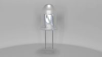
led
...led
3dexport
the led is cut with all the parts.
3ddd
$1
Monacor / PARL56DMX / LED-320RGBW / LED-345RGBW / LED-300RGB
... прожектор
http://www.monacor.dk/
parl56dmx
led-320rgbw
led-345rgbw
led-300rgb
turbosquid
$10
LED
...led
turbosquid
free 3d model led for download as blend on turbosquid: 3d models for games, architecture, videos. (1691856)
3d_export
$5

led lamp
...led lamp
3dexport
led lamp, brightness animation
3ddd
free
leds-c4
...leds-c4
3ddd
leds-c4
современный торшер
3ddd
free
leds-c4
...leds-c4
3ddd
leds-c4
настольный лампа
turbosquid
$19

LED
... available on turbo squid, the world's leading provider of digital 3d models for visualization, films, television, and games.
turbosquid
$12
Led
... available on turbo squid, the world's leading provider of digital 3d models for visualization, films, television, and games.
turbosquid
free
LED
... available on turbo squid, the world's leading provider of digital 3d models for visualization, films, television, and games.
turbosquid
free

LED
... available on turbo squid, the world's leading provider of digital 3d models for visualization, films, television, and games.
Powered
turbosquid
$100
power
...ower
turbosquid
royalty free 3d model power for download as on turbosquid: 3d models for games, architecture, videos. (1421990)
3d_export
$5

Power
...power
3dexport
3d_export
$5
power outlets
...power outlets
3dexport
power outlets
3ddd
$1
lion power
...lion power
3ddd
лев , статуя
lion power gold sculpture
3ddd
$1
Sea Power
...
компас , море , часы
часы с компасом sea power
3ddd
free
Meridiani / Power
...power
3ddd
meridiani , круглый
стол power производитель meridiani, диаметр 120,высота 67
3d_export
$5

Power Surge
...power surge
3dexport
the power surge is a all mesh carnival ride to lower in game part count and lag
turbosquid
$8
Airport Ground Power Unit (AXA Power )
... available on turbo squid, the world's leading provider of digital 3d models for visualization, films, television, and games.
turbosquid
$50

Power Houser
...rbosquid
royalty free 3d model power houser for download as on turbosquid: 3d models for games, architecture, videos. (1333800)
3d_export
$5

power outlet
...power outlet
3dexport
power outlet<br>format file maya 2018, 3d max 2017, obj, fbx
World
3d_ocean
$5
world
...world
3docean
3d earth model world
3d world model
turbosquid
$150

world
... available on turbo squid, the world's leading provider of digital 3d models for visualization, films, television, and games.
turbosquid
$30

world
... available on turbo squid, the world's leading provider of digital 3d models for visualization, films, television, and games.
turbosquid
$9

WORLD
... available on turbo squid, the world's leading provider of digital 3d models for visualization, films, television, and games.
turbosquid
$5

World
... available on turbo squid, the world's leading provider of digital 3d models for visualization, films, television, and games.
turbosquid
free

world
... available on turbo squid, the world's leading provider of digital 3d models for visualization, films, television, and games.
turbosquid
$1

world
...d
turbosquid
royalty free 3d model world for download as 3ds on turbosquid: 3d models for games, architecture, videos. (1487045)
3ddd
free
The World
... панно
багет the world. декор для стены в рамке, может так же использоваться как декор во всю стену без багета.
3d_ocean
$5

The world 3d
...the world 3d
3docean
3d map the world world
this is the 3d version of the word
3d_export
$5

a small world
...a small world
3dexport
a small world