Thingiverse
3018 CNC Engraving / Milling Machine Accessory Set by 8SquareFeet
by Thingiverse
Last crawled date: 3 years ago
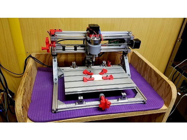
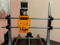
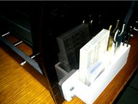
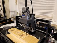
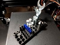
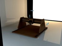
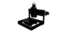
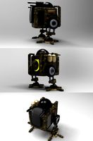
I recently purchased a little CNC Engraving Machine. They call it a "Wood Carving Milling Engraving Machine", but pretty sure it's not going to do any heavy milling. But that's OK with me. Since I already have a couple of 3D printers and a laser engraver/cutter, I wanted a small CNC "Mill" to play with. This is the model I got:
https://www.amazon.com/gp/product/B074PS7ZP6/ref=ox_sc_act_title_1?smid=A16P4TUM521SQ8&psc=1
Before I go to far, let me give credit to CaptainObvious. I did a partial remix of his "Clamp set for 4030 CNC Router" thing. https://www.thingiverse.com/thing:901649
All I basically did to his set was change the hardware from M4 to M3, because that's what I have. I've included the parts I modified here, but if you need M4 or want the whole set, go check out his thing.
OK, now that credit where due is out of the way....
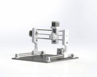
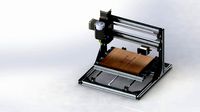
There are a lot of these little CNC machines out there, and other than work area, they're pretty much all the same. The one I got came with everything needed to assemble it, including tools, and had a few spare items left over. This one has a work area of 30 X 18 CM, but you should be able to use most of the parts even if your size is different.
After assembly, I found a few that were irritating or that I wanted to enhance:
Missing any kind of handwheels
No endstops included, so no auto-homing (I knew this when I bought it...)
No cable management
The workpiece clamps they included are jokes
Handwheels:
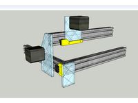
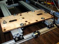
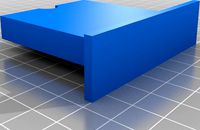
The first thing I found annoying is that the only way to move X and Y around was to either turn the lead screws by hand, or use the software. So it needed some handwheels. This was actually pretty easy. The lead screws have support bearings on the far ends of them. First I moved the X bearing/mount to the Y screw. The X bearing mount wraps around the extrusion, so to use it you can either do what I did and add some rubber feet to the bottom of the frame, or you can trim off the part the wraps around the extrusion. The 'new' Y bearing goes on the inside of the frame. This gives you a little more lead screw to use when attaching the Y handwheel.
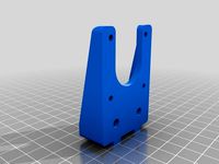
I designed a new bearing mount for the X lead screw. You use the bearing out of the old Y support. Mounting the X bearing support does take a little planning. The bearing gets pressed in after you install the mounting bolt/screw. First, run the X carriage almost all the way to left. Now take the screws out of the X stepper mount so you can slide everything to the right. Mount the the new bearing mount, but leave it loose enough to move a little if needed. Once the mount is in place, press the bearing into the mount. I had to use some pliers, but it didn't take any force at all. Now that the bearing is in place, you can slide the X assembly back to the left, running the lead screw through the bearing. Don't push it all the way through yet. You're using the X rods and lead screw to set the position of the bearing mount. Adjust the mount up and down until things look good, then go ahead and tighten the mounting bolt for the support bearing. Once tight, go ahead and slide everything the rest of the way to the left and reattach the stepper to the frame. It sounds complicated, but you'll see what I mean when you start doing it.
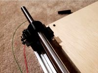
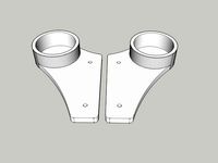
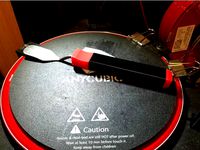
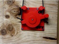
The handwheels come in two sizes. I used a large one on the X and the small one on the Y, but you could use the same size on both if you wanted to (and had clearance on the Y for it). The handwheel handle is the same for both sizes. They are designed around 3mm hardware. Place your screw through the handle and thread on a nut. Don't tighten it down. Place that assembly onto the handwheel. The nut should be in the recessed area. Attach a nut on the back of the handwheel, but don't tighten it too tight yet. Use an allen key to adjust the clearance between the handle and the first nut. The handle should spin freely on the screw. Now tighten the rear nut. You're basically squeezing the handwheel between the nuts. Once tight, the handle should still spin on the screw. If not, loosen the rear nut, adjust the screw and the retighten until you get it where you want it to be. Once you have that the way you want, install the handwheel assembly onto the lead screw. They should "screw" onto the leadscrews without too much force. You can secure the handwheels with a couple of short cap screws if you need to.
Endstops:
I knew endstops were not included before buying the kit, but I also knew the control board supported them.
WARNING: Before I go any further, you should be familiar with the "Right Hand Rule" and the way CNC machines understand that. Quoting from the GRBL wiki.... "By default, Grbl's homing cycle moves the Z-axis positive first to clear the workspace and then moves both the X and Y-axes at the same time in the positive direction." Also, "By default, Grbl assumes your homing limit switches are in the positive direction...". This means with a default GRBL config, the endstops for X and Y would opposite of the way I mounted mine.I had to modify the $23 variable (Homing dir invert mask) to get my machine doing what I wanted it to do.
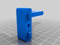
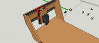
The X endstop mount mounts to the top extrusion on the frame and the switch is activated by hitting the side of the X carriage. The version I uploaded includes a small channel for wire routing.
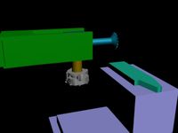
The Y endstop mounts to the lower rear extrusion of the frame. It could mount on either the left or right side. I'm using the right side because it's closer to the board. The Y endstop is triggered by a 'flag' hanging down under the work table. The flag slides into the table extrusion and is held in place by a captive nut and cap screw.
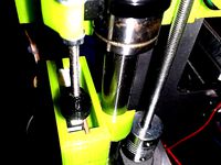
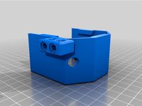
The Z endstop mount replaces 2 of the spacers under the Z stepper motor (the other spacers are replaced by X_Nema_Cable_Mnt). The Z endstop switch is activated by the Z carriage. It's tight, but it works.
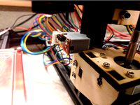
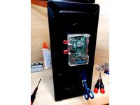
Cable management:
I used some split loom to clean up the wiring going to the carriage. The split loom clips into the spacers. I've tried to keep the spindle motor power lines mostly away from the stepper lines. Use X_Nema_Cable_Mnt to replace 2 of the Z stepper motor spacers (the other 2 are replaced with Z_Stop_Mount), keep things seperated using Cable_Spacer and secure the board ends of the wiring to the frame using Cable_Spacer_Frame_Mount.
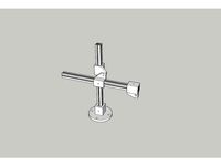
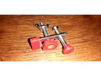
Workpiece clamps:
As I said at the top, I remixed https://www.thingiverse.com/thing:901649 to use 3mm hardware. Much better than the clamps supplied with the machine.
https://www.amazon.com/gp/product/B074PS7ZP6/ref=ox_sc_act_title_1?smid=A16P4TUM521SQ8&psc=1
Before I go to far, let me give credit to CaptainObvious. I did a partial remix of his "Clamp set for 4030 CNC Router" thing. https://www.thingiverse.com/thing:901649
All I basically did to his set was change the hardware from M4 to M3, because that's what I have. I've included the parts I modified here, but if you need M4 or want the whole set, go check out his thing.
OK, now that credit where due is out of the way....
There are a lot of these little CNC machines out there, and other than work area, they're pretty much all the same. The one I got came with everything needed to assemble it, including tools, and had a few spare items left over. This one has a work area of 30 X 18 CM, but you should be able to use most of the parts even if your size is different.
After assembly, I found a few that were irritating or that I wanted to enhance:
Missing any kind of handwheels
No endstops included, so no auto-homing (I knew this when I bought it...)
No cable management
The workpiece clamps they included are jokes
Handwheels:
The first thing I found annoying is that the only way to move X and Y around was to either turn the lead screws by hand, or use the software. So it needed some handwheels. This was actually pretty easy. The lead screws have support bearings on the far ends of them. First I moved the X bearing/mount to the Y screw. The X bearing mount wraps around the extrusion, so to use it you can either do what I did and add some rubber feet to the bottom of the frame, or you can trim off the part the wraps around the extrusion. The 'new' Y bearing goes on the inside of the frame. This gives you a little more lead screw to use when attaching the Y handwheel.
I designed a new bearing mount for the X lead screw. You use the bearing out of the old Y support. Mounting the X bearing support does take a little planning. The bearing gets pressed in after you install the mounting bolt/screw. First, run the X carriage almost all the way to left. Now take the screws out of the X stepper mount so you can slide everything to the right. Mount the the new bearing mount, but leave it loose enough to move a little if needed. Once the mount is in place, press the bearing into the mount. I had to use some pliers, but it didn't take any force at all. Now that the bearing is in place, you can slide the X assembly back to the left, running the lead screw through the bearing. Don't push it all the way through yet. You're using the X rods and lead screw to set the position of the bearing mount. Adjust the mount up and down until things look good, then go ahead and tighten the mounting bolt for the support bearing. Once tight, go ahead and slide everything the rest of the way to the left and reattach the stepper to the frame. It sounds complicated, but you'll see what I mean when you start doing it.
The handwheels come in two sizes. I used a large one on the X and the small one on the Y, but you could use the same size on both if you wanted to (and had clearance on the Y for it). The handwheel handle is the same for both sizes. They are designed around 3mm hardware. Place your screw through the handle and thread on a nut. Don't tighten it down. Place that assembly onto the handwheel. The nut should be in the recessed area. Attach a nut on the back of the handwheel, but don't tighten it too tight yet. Use an allen key to adjust the clearance between the handle and the first nut. The handle should spin freely on the screw. Now tighten the rear nut. You're basically squeezing the handwheel between the nuts. Once tight, the handle should still spin on the screw. If not, loosen the rear nut, adjust the screw and the retighten until you get it where you want it to be. Once you have that the way you want, install the handwheel assembly onto the lead screw. They should "screw" onto the leadscrews without too much force. You can secure the handwheels with a couple of short cap screws if you need to.
Endstops:
I knew endstops were not included before buying the kit, but I also knew the control board supported them.
WARNING: Before I go any further, you should be familiar with the "Right Hand Rule" and the way CNC machines understand that. Quoting from the GRBL wiki.... "By default, Grbl's homing cycle moves the Z-axis positive first to clear the workspace and then moves both the X and Y-axes at the same time in the positive direction." Also, "By default, Grbl assumes your homing limit switches are in the positive direction...". This means with a default GRBL config, the endstops for X and Y would opposite of the way I mounted mine.I had to modify the $23 variable (Homing dir invert mask) to get my machine doing what I wanted it to do.
The X endstop mount mounts to the top extrusion on the frame and the switch is activated by hitting the side of the X carriage. The version I uploaded includes a small channel for wire routing.
The Y endstop mounts to the lower rear extrusion of the frame. It could mount on either the left or right side. I'm using the right side because it's closer to the board. The Y endstop is triggered by a 'flag' hanging down under the work table. The flag slides into the table extrusion and is held in place by a captive nut and cap screw.
The Z endstop mount replaces 2 of the spacers under the Z stepper motor (the other spacers are replaced by X_Nema_Cable_Mnt). The Z endstop switch is activated by the Z carriage. It's tight, but it works.
Cable management:
I used some split loom to clean up the wiring going to the carriage. The split loom clips into the spacers. I've tried to keep the spindle motor power lines mostly away from the stepper lines. Use X_Nema_Cable_Mnt to replace 2 of the Z stepper motor spacers (the other 2 are replaced with Z_Stop_Mount), keep things seperated using Cable_Spacer and secure the board ends of the wiring to the frame using Cable_Spacer_Frame_Mount.
Workpiece clamps:
As I said at the top, I remixed https://www.thingiverse.com/thing:901649 to use 3mm hardware. Much better than the clamps supplied with the machine.
Similar models
thingiverse
free
P3Steel 2.x+ Y axis endstop mount by sigterm9
... the endstop will be trigerred by lm8 bearing. mounted by m3 screw with nut. endstop should be mounted by m2 screws without nuts.
grabcad
free

Alluminum Extrusion Stepper Motor and Bearing Mount
...pper motor, anti-backlash coupling, and bearing mounts for a cnc machine using aluminum extrusion with 1.75" channel spacing
thingiverse
free
Biqu Laser Engraver Endstop Mounts by 8SquareFeet
...imension to verify your switches will line up.
i printed these in petg, but pretty sure you could use whatever filament you like.
thingiverse
free
Makerfarm Pegasus 8" Z Endstop Mount by meie1kyl
...to the extrusion and m3's mount the board to the printed piece. will likely work on other printers made from 2020 extrusions.
thingiverse
free
Dual Makerslide y-axis parts and endstop mounts by Simonious
...en fixed and it is very nice - i've been using it for a week now with zero bolts, it snaps hard right to the 20x20 extrusion.
thingiverse
free
CNC Dremel endstop mounts
...nd adjust the length to trigger the endstop. i'm using a washer and nut to prevent the screw from being pushed into the hole.
thingiverse
free

Adjustable Z Endstop for MakerFarm Prusa i3v by clough42
...e.com/thing:321810
update: i now also have a micrometer-adjustable z endstop available: http://www.thingiverse.com/thing:356819
thingiverse
free
X-ends for holding 20x20 extrusion nuts/lm8uus by Simonious
...z-nut with spring pair - should fit m8 or similar i'm using it on acme 1/4" rods in the...
thingiverse
free
Mega Prusa i3 Z-EndStop mount by krogul
...endstops for megaprusa:
y-endstop - http://www.thingiverse.com/thing:1345831
x-endstop - http://www.thingiverse.com/thing:1345833
thingiverse
free
Reach 3D setup tools by jwass
...ugh i would have to think that with bed leveling it would be close enough as it got my column to within .015" over 13".
8Squarefeet
thingiverse
free

Cabinet Handle (Large) by 8SquareFeet
...mm self-tapping hardware.
it is a bigger handle, so it will hang out 35mm off the door on the outside.
print as many as you need!
thingiverse
free

Probe Cap for WSDCAM Cable Tester by 8SquareFeet
...y-security-firmware-upgraded-8600movtsadh-plus/dp/b00zx3b81y/ref=sr_1_2?ie=utf8&qid=1507406397&sr=8-2&keywords=wsdcam
thingiverse
free
Push out air vent by 8SquareFeet
...strength and heat resistance in the sun.
print with the largest flat side down. you will need some support for the retaining lip.
thingiverse
free
Machine Light Mount by 8SquareFeet
...ref=oh_aui_search_detailpage?ie=utf8&psc=1
i printed in pla with 45 or 50 percent infill, but it could probably do with less.
thingiverse
free
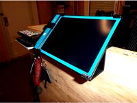
8.5" Boogie Board Mount by 8SquareFeet
...t now. i suspect it would work just as well in pla. i used 15% infill, 3 perimeters and 3 layers, but those are just my defaults.
thingiverse
free
Scraper Replacement Handle by 8SquareFeet
...d the tool rod up and pushed it into the hole.
i've included the sketchup model in case you'd like to make modifications.
thingiverse
free
Raspberry Pi Mount for Mediasonic Enclosure by 8SquareFeet
...ort usb 3 cable, and still provides access to all of the pi's io ports.
i printed this in petg, but any filament should work.
thingiverse
free
Indicator Stand (uses 15 X 15 Extrusion) by 8SquareFeet
...ll hardware is 3mm.
the files should be oriented for proper printing.
i used petg, but that's just what i had loaded already.
thingiverse
free
RGB Matrix Stand by 8SquareFeet
...no can power this small matrix without issue, but if you build a bigger one, you may want to run power directly to the led's.
thingiverse
free
Remote Light Switch by 8SquareFeet
...ect, but it works great for me. now i don't have to walk all the way to the back of a dark room to turn the light on and off.
3018
3d_export
$5

Cartoon Black Bus Car
...triangulated for the game engine. total number of polygons: 3018 ...
thingiverse
free

CNC 3018 by Assomer
...cnc 3018 by assomer
thingiverse
accessoire pour cnc diy 3018
3dfindit
free
3017, 3018
...3017, 3018
3dfind.it
catalog: 80/20
thingiverse
free
aspiration 3018
...rse
support pour brosse aspiration fraiseuse 3018
la brosse fait 69x43 mm
brosse ancien aspirateur je ne connais plus la marque
thingiverse
free
CNC 3018 rod mount
...cnc 3018 rod mount
thingiverse
rod mount for cnc 3018.
thingiverse
free
Outillage CNC 3018 Pro
...outillage cnc 3018 pro
thingiverse
ranger vos principaux outils cnc 3018 pro
thingiverse
free
CNC 3018 Calibrator by digital_technology_factory
...cnc 3018 calibrator by digital_technology_factory
thingiverse
this is a part to calibrate the rods of the z axis of the cnc 3018
thingiverse
free
CNC 3018 Dremel Mount
...d.com/custlink/vvdv4y6oc6https://amzn.to/2bjkmil
dremel 3000https://amzn.to/36bt4f9
(affiliate links! if you want to support me.)
thingiverse
free
CNC 3018 Clamp protection
...lamp protection
thingiverse
designed to protect the aluminium of the cnc 3018 and protect the wood
with a little power it fits.
thingiverse
free
CNC 3018 tools organizer
...cnc 3018 tools organizer
thingiverse
this is a tools organizer for my cnc 3018 that i designed.
feel free to use.
Engraving
turbosquid
$8

Engraved Sword
...alty free 3d model engraved sword for download as max and fbx on turbosquid: 3d models for games, architecture, videos. (1168563)
turbosquid
$10

Engraved tiger
...ree 3d model engraved tiger for download as max, obj, and fbx on turbosquid: 3d models for games, architecture, videos. (1298214)
turbosquid
$1

Engraver(General)
... available on turbo squid, the world's leading provider of digital 3d models for visualization, films, television, and games.
turbosquid
$19
Seax Knife Engraved
...model seax knife engraved for download as blend, fbx, and obj on turbosquid: 3d models for games, architecture, videos. (1497294)
3d_export
$5
scary monster engraving
...nal engraving for 3d printing will give your environment an exotic look! it will look great if you paint it in the color of stone
turbosquid
$59

Emerald Engraving Ring
... available on turbo squid, the world's leading provider of digital 3d models for visualization, films, television, and games.
turbosquid
$23

Runes Engraving Set
... available on turbo squid, the world's leading provider of digital 3d models for visualization, films, television, and games.
turbosquid
$15

Decoration Engraved table
... available on turbo squid, the world's leading provider of digital 3d models for visualization, films, television, and games.
turbosquid
$8

Viking helmet with engraved
...met with engraved for download as c4d, 3ds, dxf, fbx, and obj on turbosquid: 3d models for games, architecture, videos. (1618783)
turbosquid
$5

Engraved coffee cup
...ved coffee cup for download as blend, dae, fbx, obj, and gltf on turbosquid: 3d models for games, architecture, videos. (1713648)
Milling
design_connected
$18

Mills
...mills
designconnected
minotti mills computer generated 3d model. designed by dordoni, rodolfo.
3ddd
$1

Mille Nuits
...mille nuits
3ddd
mille nuits
люстра из коллекции mille nuits
turbosquid
$25

Mill
...ll
turbosquid
royalty free 3d model mill for download as fbx on turbosquid: 3d models for games, architecture, videos. (1292872)
turbosquid
$15

The Mill
...urbosquid
royalty free 3d model the mill for download as obj on turbosquid: 3d models for games, architecture, videos. (1459219)
turbosquid
$3
Mill
...ll
turbosquid
royalty free 3d model mill for download as max on turbosquid: 3d models for games, architecture, videos. (1233201)
turbosquid
$1

mill
...
turbosquid
royalty free 3d model mill for download as blend on turbosquid: 3d models for games, architecture, videos. (1613409)
3d_export
$10
Coffee Mill
...coffee mill
3dexport
coffee mill
3d_export
$5
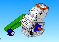
impact mill
...impact mill
3dexport
impact mill
archibase_planet
free
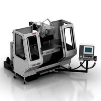
Milling machine
...base planet
milling machine miller milling-machine
milling machine vhf-680 n250413 - 3d model (*.gsm+*.3ds) for 3d visualization.
3ddd
$1

Minotti / Mills
...minotti / mills
3ddd
minotti
minotti / mills
Accessory
3ddd
$1
accessories
...accessories
3ddd
чаша
accessories
3ddd
$1

accessories
...accessories
3ddd
статуэтка
accessories
3ddd
$1

accessories
...accessories
3ddd
статуэтка
accessories
3ddd
$1

accessories
...accessories
3ddd
статуэтка
accessories
archibase_planet
free

Accessories
...accessories
archibase planet
fireplace accessories
accessories - 3d model (*.gsm+*.3ds) for interior 3d visualization.
archibase_planet
free
Accessories
...accessories
archibase planet
fireplace accessories
accessories - 3d model (*.gsm+*.3ds) for interior 3d visualization.
archibase_planet
free
Accessory
...accessory
archibase planet
art accessories design creative
accessory f1137 - 3d model for interior 3d visualization.
archibase_planet
free
Accessories
...accessories
archibase planet
kitchen ware kitchen accessories
accessories - 3d model (*.gsm+*.3ds) for interior 3d visualization.
archibase_planet
free

Accessories
...accessories archibase planet poker fireplace accessory accessories 3 - 3d model (*.gsm+*.3ds) for interior 3d...
archibase_planet
free
Accessories
...essories
archibase planet
kitchen accessories pots and pans cooking battery
accessories - 3d model for interior 3d visualization.
Cnc
3d_export
$35
Cnc
...cnc
3dexport
the cnc machine is unfinished
3d_export
$10
cnc router
...cnc router
3dexport
prototipe cnc router
3d_export
$10
cnc machine
...cnc machine
3dexport
cnc machine model with individual model files with assembly
3d_export
$5
Cnc 3D Model
...cnc 3d model
3dexport
cnc
cnc 3d model csiszar 61289 3dexport
turbosquid
$10

cnc bedroom
...osquid
royalty free 3d model cnc bedroom for download as max on turbosquid: 3d models for games, architecture, videos. (1494981)
turbosquid
$9
cnc(wood)
...rbosquid
royalty free 3d model cnc(wood) for download as max on turbosquid: 3d models for games, architecture, videos. (1189189)
turbosquid
$1

CNC Frame
...rbosquid
royalty free 3d model cnc frame for download as stl on turbosquid: 3d models for games, architecture, videos. (1371706)
turbosquid
free
cnc table
...rbosquid
royalty free 3d model cnc table for download as max on turbosquid: 3d models for games, architecture, videos. (1500926)
turbosquid
$30
CNC Lathe
...
royalty free 3d model cnc lathe for download as max and obj on turbosquid: 3d models for games, architecture, videos. (1284634)
turbosquid
$25
CNC Machine
...
royalty free 3d model cnc machine for download as ma and fbx on turbosquid: 3d models for games, architecture, videos. (1307199)
Machine
archibase_planet
free

Machine
...machine
archibase planet
sewing-machine sewing machine equipment
singer machine- 3d model for interior 3d visualization.
archibase_planet
free

Machine
...hine
archibase planet
percolator equipment coffee-machine
machine n230708 - 3d model (*.gsm+*.3ds) for interior 3d visualization.
archibase_planet
free

Machine
...chibase planet
percolator coffee-machine kitchen equipment
coffee machine - 3d model (*.gsm+*.3ds) for interior 3d visualization.
archibase_planet
free

Slot machine
...ase planet
slot machine slot-machine playing machine
slot machine n260311 - 3d model (*.gsm+*.3ds) for interior 3d visualization.
turbosquid
$7

Machine
...ne
turbosquid
royalty free 3d model machine for download as on turbosquid: 3d models for games, architecture, videos. (1391792)
3d_ocean
$10
War machine
...war machine
3docean
camuflage machine robot war war machine
war machine created in 3dmax 2009 15.497-poly count
turbosquid
$7

machine
...turbosquid
royalty free 3d model machine for download as obj on turbosquid: 3d models for games, architecture, videos. (1452674)
3d_ocean
$12
Weighing-machine
...weighing-machine
3docean
market shop weighing-machine
3d model weighing-machine
archibase_planet
free

Sewing machine
...ine
archibase planet
sewing machine sewing-machine
sewing machine n080311 - 3d model (*.gsm+*.3ds) for interior 3d visualization.
archibase_planet
free
Coffee machine
...se planet
coffee machine percolator coffee-machine
coffee machine n010715 - 3d model (*.gsm+*.3ds) for interior 3d visualization.
Set
archibase_planet
free

Setting
...setting
archibase planet
setting cover place setting
setting - 3d model (*.gsm+*.3ds) for interior 3d visualization.
archibase_planet
free
Setting
...setting
archibase planet
setting place setting cover
setting - 3d model (*.gsm+*.3ds) for interior 3d visualization.
archibase_planet
free

Setting
...setting
archibase planet
setting place setting cover
setting - 3d model (*.gsm+*.3ds) for interior 3d visualization.
3d_export
$8

decorative set mens set
...decorative set mens set
3dexport
decorative set men's set
archibase_planet
free
Set
...anet
set kitchen ware kitchen set kitchen tools
set kitchen tools n281114 - 3d model (*.gsm+*.3ds) for interior 3d visualization.
archibase_planet
free
Set
...set
archibase planet
beer set bar equipment
beer set - 3d model for interior 3d visualization.
archibase_planet
free

Set
...set
archibase planet
cover place setting
set - 3d model (*.gsm+*.3ds) for interior 3d visualization.
archibase_planet
free

Set
...set
archibase planet
kitchen set kitchen ware
set - 3d model (*.gsm+*.3ds) for interior 3d visualization.
archibase_planet
free

Set
...set
archibase planet
set cup glass kitchen ware
set - 3d model (*.gsm+*.3ds) for interior 3d visualization.
archibase_planet
free

Set
...set
archibase planet
flatware cover place setting
set n311210 - 3d model (*.gsm+*.3ds) for interior 3d visualization.