Thingiverse
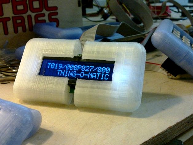
Thing-O-Matic LCD Temperature Readout by ScribbleJ
by Thingiverse
Last crawled date: 2 years, 11 months ago
I don't know why Thingiverse puts the descriptions in this order and makes you read through my extreme verbosity just to get to some instructions...
Cupcake users have been rigging up LCDs for a while, but as far as I (and the Firmware, and the RepG code) know, no one has done it on a Thing-O-Matic. I guess the latest RepG monitors temperatures, so that's nice, but I had this LCD in a box and I thought finally - something to use it on.
Yes, this has no keypad, but even if you have /nothing/ in your workshop, the total project cost for this is < $20.
It turned out to be a bit of a slog, since there was literally nothing written for it in the Thing-O-Matic firmware. But worse than that, since I personally have two extruders, and I hope others will follow ( http://www.thingiverse.com/thing:6632 ) ... it didn't make sense to hook it to the extruder controller as is traditional. It made sense to hook it to the motherboard.
This brings in a whole raft of problems. The motherboard firmware has never known the toolhead temperature. It doesn't really have any way to know. So I had to add one. Because the only way to get the temperatures is a round-trip comm with the extruder, this is a little costly; but I think in the latest version I've managed to completely eliminate any delays.
IMPORTANT NOTES FOR YOU!
I didn't bother to separate out the code for my estop ( http://www.thingiverse.com/thing:6704 ) from the below, so if you use the .patch file or firmware as-is you get both, but if there's nothing wired up to your estop it doesn't matter anyhow.
It's always best if you can use the .patch file to compile your own firmware. The .hex file attached is hardcoded to assume 1 toolhead, and prints "THING-O-MATIC" in the extra space. It also assumes you're using a 16x2 display with Hitachi addressing, so something like the black/white one from Sparkfun and NOT like my green Newhaven.
Any news below about delays is old news. What's published here is the final version and works brilliantly in all my tests.
The .STL files below are for my Newhaven display and are much too big for the Sparkfun displays. It'll probably be down to someone else to design a nice case for this.
If you are using your X-MAX endstop (you probably are using X-MIN, not X-MAX) the published .hex file will disable it. Use the .patch file and re-enable it or... well, no or really. You're on your own here. :) I don't think this will actually be an issue for anyone, I've never heard of anyone using X-MAX.
This also disables the debug LED on the motherboard.
UPDATE: (2011-03-01)
It does introduce delays. By splitting things up so that it doesn't try to do everything at once, the delays are vastly reduced, but not, I think, eliminated. However, there may be more I can do, and suggestions are welcome. I'll be uploading a new patch later tonight after I do some more work that will solve at least most of the problem.
Patch still pending; I've uploaded a plan for a LCD Case, which so far I've printed the smaller half of and it fits great. I've got a plan for fixing the delay completely; it turns out the LCD library form Arduino is stupid and sits and waits after each character for 100us. Assuming this adds up pretty quickly, but the LCD actually does require almost 100us to process a command, the sane thing to do is to pulse the line on, go on and do something else, and come back after about 100us to turn it off. This is easy to accomplish and when I upload the patch it'll have this change, but it may not be for several hours as I'm knee-deep in my day job right now.
-- new patch and firmware uploaded. These make a huuuuuuge improvement in how the LCD Library works, so there's fundamentally no delay there. But the querying of the extruders does still sometimes introduce a delay I still need to solve. I'm not sure how (or if - haven't used it myself) RepG is able to query for the temp during a print without causing minor interruptions...
But I'm imagining the solution is something like putting a check temperature command into the queue instead of just /doing/ it like I am now... since that'll make it fundamentally equivalent to whatever RepG is accomplishing.
So that'll be my next step... another pretty big one probably.
UPDATE: (2011-03-04)
Sorry for the delays on this one; my day job has been just killer lately and I've had to fit in ToM development where I can.
I got the LCD display I linked below from Sparkfun, and it turns out some of the assumptions I made about how these things work generally, extrapolated from the one I was using, were incorrect. It's not any major thing; the one wire I hooked up 'even though it's not used' turns out to be an analog contrast adjustment pin on most of these LCDs, so should be attached to a pot to make an easy contrast knob; or maybe PWM'd from the pin it's on now would work? Not sure; I'll probably go with the pot...
And a reason for that is I've recieved the $3 keypad mentioned in the comments. It needs 7 pins to drive. If you're keeping score at home, that makes 23 pins total used between the keypad and LCD, and the ToM expansion port only has 22 pins. If I take out the LCD contrast pin and run it through a pot, that frees up the final needed pin. However, I'm not doing that right now; I'm stealing the unused pin out of the x-max endstop.
There will be an updated firmware up sometime today that shows the beginnings of keypad support and HOPEFULLY clears up the last of the delays from polling the tools.
Incidentally, I looked over the cupcake LCD code by Revar to see how it was done there, and it seems to be on an unmaintained, outdated version of the code, sadly. (If I'm wrong, correct me!) It's too bad the stuff I'm putting together here is not likely to work for cupcake users without some modification. I did find some inspiration there for how to approach things overall, but not a lot, as that architecture is very different... not just that old firmware, but also his design -- it costs so much more to put together his because is uses i2c; it only needs a few pins to drive everything. Here the total cost is < $20 in dollars but about 22 in pins. Still, what ELSE are you going to use all those pins for?
No beginnings of keypad support in the code /as such/ but you will find the firmware below now clears up all delays... so it works perfectly as advertised.
UPDATE: (2011-03-05)
Tested with 16x2 display from Sparkfun:http://www.sparkfun.com/products/709
This should also apply to the following (at least):http://www.sparkfun.com/products/255http://www.sparkfun.com/products/791http://www.sparkfun.com/products/790http://www.sparkfun.com/products/256 4 lines!
I needed to tweak the firmware just the tiniest amount to fix up the support for the Hitachi standard, as the 20x2 Newhaven I had been using has some odd quirks. Now the patch should support either one, but the firmware below is compiled for the 16x2 from Sparkfun -- oops, and two toolheads. I'll recompile and upload it again shortly. As always, it's best if you can use the patch and compile your own!
I've uploaded some comparison photos.
The case I made for the sparkfun LCD failed to take into account the extended length of the backlighting, and so does not fit. I don't need to upload it; it's the same code as the other case just with the measurements changed.
I do still owe you all a new firmware, and I'll upload it tomorrow. I've got the keypad (linked below in the comments) up and running and I expect Big Things for tomorrow!
UPDATE: (2011-03-06)
I'm putting a DONE stamp on this. As a temperature readout for the Thing-O-Matic, it's complete and there are no issues I am aware of remaining. The published version of the firmware below is compiled with the patch labeled "finalprobably," which is just what it says.
Similar models
thingiverse
free

Sparkfun 12 Button Keypad by deisterhold
...sparkfun 12 button keypad by deisterhold
thingiverse
sparkfun keypadhttps://www.sparkfun.com/products/8653
thingiverse
free

Thing-O-Matic 4-Axis Stepper Extruder by ScribbleJ
... come crying to me. if you want to do it right, get the firmware from the git repo and compile it yourself. it's not hard.!
thingiverse
free

Housing for modtronix 4x4 keypad by jag
...for an rj45 connector so you can use a standard cat5 patch cable to connect it to an lcd in http://www.thingiverse.com/thing:6379
thingiverse
free

Keypad/LCD Mounting Bracket by ScribbleJ
...'t actually printed it yet; too big to print on the tom and the prusa z axis is getting replaced before i print again there.
thingiverse
free

Thing-O-Matic Control Panel by ScribbleJ
...d running on github. let me know if i'm doin' it right. quite a bit different than my svn!
https://github.com/scribblej
thingiverse
free

3D Printed Geiger Counter by Conrad2468
...code is available on request (i'm still fiddling with it so i'm hesitant to release it!).
https://youtu.be/zelxr_wnrry
thingiverse
free

Stand for Moto Droid by qfe0
... using sketchup.
once i've had a chance to clean up the .skp, i'll upload it as well.
i look forward to any comments. :-)
3dwarehouse
free

Sparkfun Serial Enabled 16x2 LCD - Black on Green
... accurate to ~ .01mm. but these parts are hand soldered, so yours is probably constructed differently. #lcd #make_parts #sparkfun
grabcad
free

Sparkfun Serial Enabled 16x2 LCD
...lcd
grabcad
rough model of the serial enabled 16x2 lcd, i needed to design an enclosure.
https://www.sparkfun.com/products/9395
thingiverse
free

Wire Holder by Bob8898
...e holes. it is designed to hold 6 spools of wire... the wire can be found on sparkfun: https://www.sparkfun.com/products/11367
:)
Scribblej
thingiverse
free
ScribbleJ CoreXY Beta by ScribbleJ
...j/corexy-v1https://github.com/scribblej/corexy-v1#corexy-beta
full gallery of development photos here: http://imgur.com/a/donun
thingiverse
free

RAMPS Clip-on Fanmount by ScribbleJ
...ramps clip-on fanmount by scribblej
thingiverse
simple clip-on mount for 40mm cooling fan.
thingiverse
free

Endcap for Pipe or Rod by ScribbleJ
...endcap for pipe or rod by scribblej
thingiverse
simple, customizable endcap for pipe or rod, with optional setscrew.
thingiverse
free

Chapstick Holder by ScribbleJ
...hapstick holder for bicycles!
you might ask "why?" and i couldn't tell you. this item was requested by a friend.
thingiverse
free
Parametric Pen Clip by ScribbleJ
...en clip by scribblej
thingiverse
useful for anything cylindrical. i use it to make clips for my electronic cigarette batteries.
thingiverse
free

Parametric Pipe Mounting Flange by ScribbleJ
...c pipe mounting flange by scribblej
thingiverse
for mounting pipes and rods to flat things -- for example, a shower curtain rod.
thingiverse
free

ScribbleJ's Ring Sizer with Embossed Labels by vandarin
...scribblej's ring sizer with embossed labels by vandarin
thingiverse
added text to the rings.
thingiverse
free

OpenSCAD Bend Module by ScribbleJ
...se
nothing fancy at all, just makes a bend in a cube.
update: as unfancy as it was, a minor bug means i posted a new version.
thingiverse
free
(Yet Another) Printable Quad Frame by ScribbleJ
...(yet another) printable quad frame by scribblej
thingiverse
i'll update this later. maybe.
thingiverse
free

Simple Prusa Spool Mount by ScribbleJ
...ount by scribblej
thingiverse
just a quick and dirty way to mount a spool to your prusa without having to disassemble anything.
Readout
3d_export
$30

Digital Caliper 3D Model
...digital caliper 3d model 3dexport digital caliper measure measuring readout accuracy digit scale gauge precision metalworking mechanical engineering gunsmithing...
3d_export
$9

marantz sr7013
...emission shader with a light blue hue and lastly "readoutquot; needs an emission shader in...
3d_export
$30

sephora bridge in obj and fbx format
...the last 2340`s.<br>three sit-down consoles behind the captain displayed readout for the engineering, communication, and science departments.<br>unlike later bridge...
thingiverse
free

Water Meter camera readout holder
...r meter camera readout holder
thingiverse
complete project is described here https://github.com/luc3as/watermeter-readout-camera
thingiverse
free

LR44 Battery Cover for Planer Digital Readout by tayarimoto
... other devices that use lr44 batteries, such as calipers.
the fitment is tight, by design, so it can't fall off incidentally.
thingiverse
free

3d Printer Filament Length Readout
... this, maybe just an idea to do something simular would be good.
ps here is a link to my 5v to 3v3 volt converter
cheers
kisssys
thingiverse
free

Osciliscope Probe Readout Adapter by dteck
...istor lead to contact the ring on the scope.
i'm including the sketchup file for anyone who may want to modify this design.
thingiverse
free

Hobby Lathe Digital Readout by Kisssys
...t off and do the other 2 screws. it's plastic so go easy. just takes a little turn to snug it up on the rail.
cheers
kissys
thingiverse
free

sports bracelet for Abbott Freestyle Libre by wassi
...to carry the abbott freestyle libre flash glucose monitoring readout device like a clock during sports activities like running...
thingiverse
free

Case for connected Temperature/Humidity device
...a case for my connected temperature/humidity sensor with lcd readout build. more details of the build can be found...
Matic
3d_ocean
$25

motorcycle matic
...cycle matic polygons transportation
-motorcycle matic -blender, obj, fbx. -rigged and ready to animate. -uvw,texture and shading.
turbosquid
$40

Motorcycle Matic
...quid
royalty free 3d model motorcycle matic for download as on turbosquid: 3d models for games, architecture, videos. (1291136)
turbosquid
$8

Pencil Bic Matic
... available on turbo squid, the world's leading provider of digital 3d models for visualization, films, television, and games.
turbosquid
$9

matic network black coin
...ty free 3d model matic network black coin for download as max on turbosquid: 3d models for games, architecture, videos. (1458291)
turbosquid
$4
Retro Egg-O-Matic
... available on turbo squid, the world's leading provider of digital 3d models for visualization, films, television, and games.
turbosquid
$1

Dr No The Drive-o-Matic
... available on turbo squid, the world's leading provider of digital 3d models for visualization, films, television, and games.
turbosquid
$5

crave O matic Crusher robot
...atic crusher robot for download as ma, obj, fbx, dae, and stl on turbosquid: 3d models for games, architecture, videos. (1300435)
3d_export
$11

tune o matic guitar bridge shaller
...cale model of a real tune o matic guitar bridge of shaller done mainly from several image references and similar physical bridge.
turbosquid
$25

Mold-A-Matic shark wax figure 3D Printable
...del mold-a-matic shark wax figure for download as stl and obj on turbosquid: 3d models for games, architecture, videos. (1530602)
turbosquid
$45

Les Paul guitar with tune-o-matic bridge
... available on turbo squid, the world's leading provider of digital 3d models for visualization, films, television, and games.
Temperature
3d_ocean
$9

Temperature Controlled Shaker
...ure
multitherm temperature controlled shaker model. centered, no quads. ready for texturing and animations. rendered in keyshot 4
turbosquid
$18
Convectors Ntherm and temperature controller Vartronic
...rature controller vartronic for download as max, fbx, and obj on turbosquid: 3d models for games, architecture, videos. (1553379)
turbosquid
$12

Dryer high temperature mechanical and electrical factory
...rature mechanical and electrical factory for download as max on turbosquid: 3d models for games, architecture, videos. (1615409)
3d_export
$12

Temperature Control Travel Mug
...; x 2.84" x 7.62"<br>- model parts: 2<br>- material count: 2<br>- xform: yes<br>- boxtrick: yes
3d_export
$7

GEARBOX BUSHING PEUGEOT 307
...bushing peugeot 307 3dexport print material - elastan\tpu nozzle temperature - 230°с bed temperature - 100°с layer height -...
3ddd
$1

Wash Basin with light indicator
...indicator 3ddd wash basin with light indicator according to temperature ...
3d_ocean
$6
Low Profile Radiator
...low profile radiator 3docean heat heater hot pipe radiator temperature thermostat warm a low profile version of the...
3d_ocean
$6

Radiator
...radiator 3docean copper heat home house joints pipe radiator temperature thermostat warm a normal radiator with pipes and...
archibase_planet
free

Thermometer
...thermometer archibase planet thermometer temperature gauge sauna equipment thermometer - 3d model (*.gsm+*.3ds) for...
archive3d
free

Thermoregulator 3D Model
...thermoregulator 3d model archive3d thermoregulator thermostat temperature controller thermoregulator 1 - 3d model (*.gsm+*.3ds) for interior...
Lcd
turbosquid
$20

lcd
... available on turbo squid, the world's leading provider of digital 3d models for visualization, films, television, and games.
turbosquid
$15

LCD
... available on turbo squid, the world's leading provider of digital 3d models for visualization, films, television, and games.
turbosquid
$10
LCD
... available on turbo squid, the world's leading provider of digital 3d models for visualization, films, television, and games.
turbosquid
$10

LCD
... available on turbo squid, the world's leading provider of digital 3d models for visualization, films, television, and games.
turbosquid
$2

lcd
... available on turbo squid, the world's leading provider of digital 3d models for visualization, films, television, and games.
turbosquid
$1

lcd
... available on turbo squid, the world's leading provider of digital 3d models for visualization, films, television, and games.
turbosquid
free
lcd
... available on turbo squid, the world's leading provider of digital 3d models for visualization, films, television, and games.
turbosquid
free

LCD
... available on turbo squid, the world's leading provider of digital 3d models for visualization, films, television, and games.
3ddd
$1

Noti Lcd Sofa
...noti lcd sofa
3ddd
noti , lcd
3d model of noti lcd sofa
3d_ocean
$7

Lcd tube wall
...hrome electronic electronic lcd tv videowall
lcd tube wall you can put in the lcd your own texture or movie in it and animate it.
O
design_connected
$13

O Tables
...o tables
designconnected
oxdenmarq o tables computer generated 3d model. designed by marquart, dennis.
design_connected
$11

O Bench
...o bench
designconnected
robert kuo o bench computer generated 3d model. designed by kuo, robert.
design_connected
$9

Doble O
...doble o
designconnected
nomon doble o computer generated 3d model. designed by reina, josé maría.
design_connected
$11

O-Nest
...o-nest
designconnected
moroso o-nest seating objects computer generated 3d model. designed by tord boontje.
turbosquid
$2

skillet casseroles o sarten o caserola
... available on turbo squid, the world's leading provider of digital 3d models for visualization, films, television, and games.
3ddd
$1

Foscarini O-Space
...foscarini o-space
3ddd
foscarini , o-space
o-space, suspension
design luca nichetto
turbosquid
$20

Ring O
...
turbosquid
royalty free 3d model ring o for download as stl on turbosquid: 3d models for games, architecture, videos. (1353794)
turbosquid
$5

Letter O
...urbosquid
royalty free 3d model letter o for download as max on turbosquid: 3d models for games, architecture, videos. (1408519)
turbosquid
$5

Letter O
...urbosquid
royalty free 3d model letter o for download as max on turbosquid: 3d models for games, architecture, videos. (1408496)
turbosquid
$5

Letter o
...urbosquid
royalty free 3d model letter o for download as max on turbosquid: 3d models for games, architecture, videos. (1408493)
Thing
turbosquid
free

spinny thing
...ng
turbosquid
free 3d model spinny thing for download as max on turbosquid: 3d models for games, architecture, videos. (1414103)
turbosquid
$9

The decorated Thing
...royalty free 3d model the decorated thing for download as obj on turbosquid: 3d models for games, architecture, videos. (1634636)
turbosquid
$2

HORROR THINGS
...quid
royalty free 3d model horror things for download as fbx on turbosquid: 3d models for games, architecture, videos. (1316296)
turbosquid
$1

Stone things
...osquid
royalty free 3d model stone things for download as ma on turbosquid: 3d models for games, architecture, videos. (1252237)
turbosquid
$90

the thing - Vyzandan
... available on turbo squid, the world's leading provider of digital 3d models for visualization, films, television, and games.
turbosquid
free

Yellow Thing
... available on turbo squid, the world's leading provider of digital 3d models for visualization, films, television, and games.
turbosquid
free

Ball Thing
... available on turbo squid, the world's leading provider of digital 3d models for visualization, films, television, and games.
3d_export
$20

The Thing 3D Model
...the thing 3d model
3dexport
slender alien horror monster enemy scary
the thing 3d model ileon18 99013 3dexport
3d_ocean
$5

Marvel Comics Thing
... poly count (triangles): 4056. files : .obj (multi format), .3ds (multi format), .fbx (multi format), .max (2011-2012-2013-2014).
3d_export
$5

the thing
...d and animated with meta-rig<br>particle system hair for fur<br>blend,fbx,obj,colada and abc files<br>unwrapped