Thingiverse
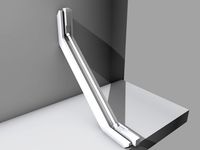
Prusa I3 MK2 M8 Brace (rear) Independent by Verskon
by Thingiverse
Last crawled date: 3 years ago
6 Month update: Overall, overkill. For a few dollars and hours' time, it was worth it while being still ungainly, ugly and heavy. Much of the desired stiffening has been achieved with new designs (ie I3 Mk3) but if you don't want the money layout required for extrusion channeling, or a new printer, additional bracing with M8 rods and secured footers is helpful. The paver's sound dampening brought noise levels down far enough so I could print overnight without being awakened from a few rooms away (I'm fairly sensitive to intermittent noises). Quieter fans and an enclosure with sound blanket took care of the rest.
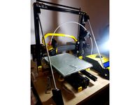
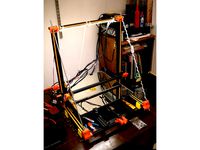
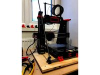
I liked aspects of the various Prusa I3 Mk2 frame braces on Thingiverse so I made my own in Fusion 360. In conjunction with a z-frame brace https://www.thingiverse.com/thing:1895661, x-frame brace https://www.thingiverse.com/thing:2438948 and TPU booties the printer is incredibly rigid and quiet. I believe this will improve high speed prints and has improved acoustics.
Update: After upgrading my Mk2s with frame braces my printing quality has improved markedly with both 400u and 250u brass nozzles in PLA. Printing at 40mm/s and 25mm/s Slic3r Prusa Edition perimeter default speeds respectively, .75mm dia meshmixer supports are actually printed successfully and cleanly removed from model and there's been less hairs and stringing on models overall. I can't tell if overall dimensional accuracy has improved but with less material needed and post-processing time required, I'm very happy. I can't tell a difference with ABS because I didn't print with it much before upgrade but the 400u prints so far have been very clean prints (so long as I use sufficient numbers of supports for the overhang).
Note before beginning: I removed the PSU and modified the Rambo case. You don't have to modify the Rambo case, just move that leg back a bit more. I moved the PSU out of the enclosure b/c I print with ABS as well.
Parts:
2x 400mm 5/16" or M8 threaded rods
8x 5/16" or M8 nuts
6x washers 9mm ID/18mm OD
4x 18mm M3 bolts
4x M3 nuts
4x 6-32 or M3.5 bolts and washers or screws to secure lower brace to base.
1x rigid base at least 400 mm x 400 mm. Concrete paver or 1/2"+ MDF board.
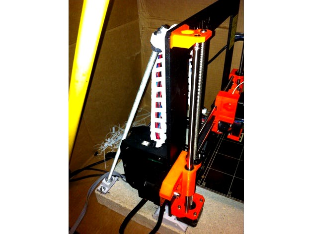
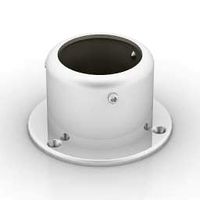
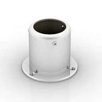
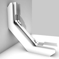
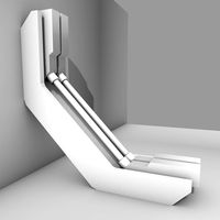
This rear brace is designed to be secured to a base independent of the printer frame so vibrations are not transferred directly to the rest of the printer. I used a concrete paver for more vibration dampening https://www.youtube.com/watch?v=OnfYA5QLA84 and rigidity.
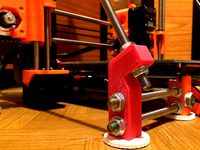
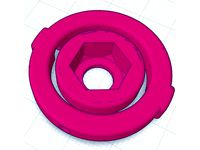
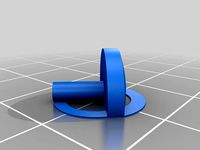
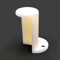
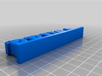
The lower brace uses a captured bottom nut. I used the threaded rod and a nut and washer on top of the lower brace to screw the bottom nut into the lower brace's cavity till it's bottomed out. If it's too tight (for an M8 nut), simply enlarge the lower brace a few %. The rod bottom should be flush with the bottom nut's bottom so the lower brace can sit flush on the base.
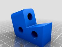
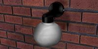
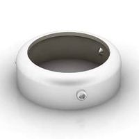
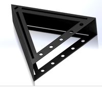
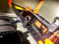
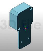
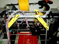
The upper brace will need supports when printing on its side but I left them oriented that way to transfer stresses from the frame to the M8 rod via filament strands instead of filament bonding layers. I used the extra 18mm-20mm M3 bolts and nuts from the MK2S kit to secure the upper brace to the frame. Simply snip any extra material away if you're using larger bolts or nuts.
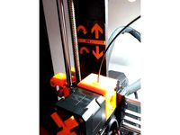
Assembly: Remove PSU. Assemble lower brace on one end of threaded rod. Emplace upper brace (designed for upper z-axis screw holes) to z frame. Thread a nut and washer on free end of the threaded rod before inserting into the upper brace. Test fit positions and clearances. The back of the lower brace is designed to be 170mm from the Z-axis frame. Mark positions and drill holes. I used epoxy anchored 35mm 6-32 bolts in 1/4" holes sunk in a 400x400x40mm concrete paver to secure the Z-frame braces, lower braces and x-axis braces (sequentially in that order). A 1/2"+ board of plywood or MDF with wood screws would work too (and be a bit easier) but I think the paver was worth it. Install vibration feeties to printer frame feet if so inclined.
After securing the lower brace to the base, lightly finger tighten the top upper brace nut and washer so it's snug but doesn't deflect the z-frame. Tighten bottom upper brace nut and washer. In conjunction with already installed z-frame brace, the frame should be super rigid now. If no z-frame brace, x-axis braces would secure the printer frame to the base creating a rigid structure as well.
I used some TPU flexible feeties with .45 mm thickness on the printer's 4 x/y axis feet to equal the z-Frame brace's .45 mm offset ( I printed with 3x .15mm layers). Also made some flexible anti-vibration pads for the paver for better vibration transmission isolation. Overall leveling achieved with cardboard scraps under anti-vibration pads.
I liked aspects of the various Prusa I3 Mk2 frame braces on Thingiverse so I made my own in Fusion 360. In conjunction with a z-frame brace https://www.thingiverse.com/thing:1895661, x-frame brace https://www.thingiverse.com/thing:2438948 and TPU booties the printer is incredibly rigid and quiet. I believe this will improve high speed prints and has improved acoustics.
Update: After upgrading my Mk2s with frame braces my printing quality has improved markedly with both 400u and 250u brass nozzles in PLA. Printing at 40mm/s and 25mm/s Slic3r Prusa Edition perimeter default speeds respectively, .75mm dia meshmixer supports are actually printed successfully and cleanly removed from model and there's been less hairs and stringing on models overall. I can't tell if overall dimensional accuracy has improved but with less material needed and post-processing time required, I'm very happy. I can't tell a difference with ABS because I didn't print with it much before upgrade but the 400u prints so far have been very clean prints (so long as I use sufficient numbers of supports for the overhang).
Note before beginning: I removed the PSU and modified the Rambo case. You don't have to modify the Rambo case, just move that leg back a bit more. I moved the PSU out of the enclosure b/c I print with ABS as well.
Parts:
2x 400mm 5/16" or M8 threaded rods
8x 5/16" or M8 nuts
6x washers 9mm ID/18mm OD
4x 18mm M3 bolts
4x M3 nuts
4x 6-32 or M3.5 bolts and washers or screws to secure lower brace to base.
1x rigid base at least 400 mm x 400 mm. Concrete paver or 1/2"+ MDF board.
This rear brace is designed to be secured to a base independent of the printer frame so vibrations are not transferred directly to the rest of the printer. I used a concrete paver for more vibration dampening https://www.youtube.com/watch?v=OnfYA5QLA84 and rigidity.
The lower brace uses a captured bottom nut. I used the threaded rod and a nut and washer on top of the lower brace to screw the bottom nut into the lower brace's cavity till it's bottomed out. If it's too tight (for an M8 nut), simply enlarge the lower brace a few %. The rod bottom should be flush with the bottom nut's bottom so the lower brace can sit flush on the base.
The upper brace will need supports when printing on its side but I left them oriented that way to transfer stresses from the frame to the M8 rod via filament strands instead of filament bonding layers. I used the extra 18mm-20mm M3 bolts and nuts from the MK2S kit to secure the upper brace to the frame. Simply snip any extra material away if you're using larger bolts or nuts.
Assembly: Remove PSU. Assemble lower brace on one end of threaded rod. Emplace upper brace (designed for upper z-axis screw holes) to z frame. Thread a nut and washer on free end of the threaded rod before inserting into the upper brace. Test fit positions and clearances. The back of the lower brace is designed to be 170mm from the Z-axis frame. Mark positions and drill holes. I used epoxy anchored 35mm 6-32 bolts in 1/4" holes sunk in a 400x400x40mm concrete paver to secure the Z-frame braces, lower braces and x-axis braces (sequentially in that order). A 1/2"+ board of plywood or MDF with wood screws would work too (and be a bit easier) but I think the paver was worth it. Install vibration feeties to printer frame feet if so inclined.
After securing the lower brace to the base, lightly finger tighten the top upper brace nut and washer so it's snug but doesn't deflect the z-frame. Tighten bottom upper brace nut and washer. In conjunction with already installed z-frame brace, the frame should be super rigid now. If no z-frame brace, x-axis braces would secure the printer frame to the base creating a rigid structure as well.
I used some TPU flexible feeties with .45 mm thickness on the printer's 4 x/y axis feet to equal the z-Frame brace's .45 mm offset ( I printed with 3x .15mm layers). Also made some flexible anti-vibration pads for the paver for better vibration transmission isolation. Overall leveling achieved with cardboard scraps under anti-vibration pads.
Similar models
thingiverse
free

anet a8 frame brace back y axis by nclsdf
...d two m8 washers.
front brace versions : http://www.thingiverse.com/thing:1844448
and : http://www.thingiverse.com/thing:1860060
thingiverse
free
Tarantula Z-Brace for 8mm threaded rod by Toxothrix
...ner braces. lower piece is unchanged.
works with 8mm or 5/16" threaded rod. 43cm per side. i've used 8 standard m8 nuts.
thingiverse
free

Z-axis reinforcement for Prusa i3 MK2 by R0peE
...s design: https://www.thingiverse.com/thing:1656945
modified the parts to be lighter, consuming less plastic and faster to print.
thingiverse
free
Prusa i3 Z-axis reinforcement by Shii
...x m3 25mm screw
4x m3 nut (preferably nylon insert locking nuts)
based on design by cylgomhttp://www.thingiverse.com/thing:397469
thingiverse
free
Z M8 Nut Inner by darkpiro
...will work for standard m8 nuts. you will have to press it in a little but that's a good thing. don't want it falling out.
thingiverse
free
CR-10 S5 Frame Stiffener by visualtrek
...the endcaps that came with the printer on the upper & lower extrusions,
or the 3d printed frame stiffener parts won't fit
thingiverse
free
Hictop Frame Reinforcement - Stabilize frame and reduces wobble and vibrations by igortopolski
...t bend that much.
if you like my design make sure you let me know in comments as i'd love to know what people think about it!
thingiverse
free

Anet A8 Frame Brace X-Axis Reinforcment by Phonogramm
...anet a8 frame brace x-axis reinforcment by phonogramm
thingiverse
03 x m8 threaded rod 400mm
12 x m8 nuts
04 x 45mm washers
thingiverse
free

anet a8 front brace Y axis by nclsdf
...ll need 2x m8 nuts, 2x m8 washers 2x m3 nuts 2x m3 bolts 30mm long.
back brace version : http://www.thingiverse.com/thing:1844389
thingiverse
free
Prusa i3 Z support lower Y corner mount M8 rod by wayne69x
...prusa i3 z support lower y corner mount m8 rod by wayne69x
thingiverse
y axis corner for z brace - all m8 threaded rod
Verskon
thingiverse
free
M3_Push_Pin by Verskon
...r m3 hole where friction fit can keep everything together. printed in abs. snap or cut off tabs. superglue into hole if paranoid.
thingiverse
free

Pokemon EEVEE Vaporeon Coin Token by Verskon
...urs, the pokemon tokens all went first. besides, there's tons of evolution for theming year to year.
gotta collect them all!
thingiverse
free
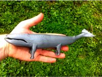
Adopt A Landwhale - Ugly Americans by Verskon
...for more stability.
i cut off the rear feet to add flippers to the ankles. a small studded leather harness was used for contrast.
thingiverse
free

608 Bearing BB by Verskon
... 608_bearing_bb_3.90_2.3_2.25 and the various iteration parts so you can mix and match so long as the raceway offset is the same.
thingiverse
free

608 Bearing Airsoft 6mm by Verskon
...s://www.thingiverse.com/thing:2229433 is a good option for slightly looser tolerances but better pre-breakin spin time than mine.
thingiverse
free
Filament Spool Hub For 608 Bearings by Verskon
...418959), printed washers and rod clips.
design inspired by https://www.thingiverse.com/thing:2135132. easy to make in fusion 360.
thingiverse
free

Anchor Hook Tie down for M3 - M12 Threaded Rod or Prusa I3 frame by Verskon
...e for screw or bolt is offset for ease of nut application and torquing.
i left v1 in case someone needs really close tolerances.
thingiverse
free
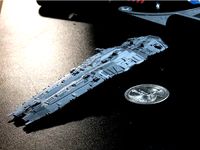
Hiigaran Battlecruiser - Maximum Battleship Homeworld 2 by Verskon
...del stand, turret mounting mechanism for turret rotation, fix eye of horus symbol for printing, design articulated barrel turrets
thingiverse
free

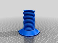
Turntable for Airbrush, Painting, Modeling Photos Rotating, 608 or BB bearing by Verskon
...thing:2111631, redesign for threaded section connecting, improve top 608 bearing stability (wide base structure/ roller wheels/ )
Mk2
turbosquid
$4

Mk2
...
royalty free 3d model mk2 for download as max, obj, and fbx on turbosquid: 3d models for games, architecture, videos. (1305687)
turbosquid
$9
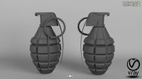
Mk2 Grenade
...osquid
royalty free 3d model mk2 grenade for download as fbx on turbosquid: 3d models for games, architecture, videos. (1175401)
turbosquid
$4

Mk2 Grenade
...quid
royalty free 3d model mk2 grenade for download as blend on turbosquid: 3d models for games, architecture, videos. (1228888)
turbosquid
$2

mk2 Grenade
...osquid
royalty free 3d model mk2 grenade for download as fbx on turbosquid: 3d models for games, architecture, videos. (1329079)
turbosquid
$2

GRENADE MK2
...osquid
royalty free 3d model grenade mk2 for download as fbx on turbosquid: 3d models for games, architecture, videos. (1202615)
turbosquid
$2

Grenade Mk2
...osquid
royalty free 3d model grenade mk2 for download as max on turbosquid: 3d models for games, architecture, videos. (1658201)
turbosquid
$75

Lanchester Mk2
...alty free 3d model lanchester mk2 for download as 3ds and max on turbosquid: 3d models for games, architecture, videos. (1497085)
turbosquid
$10

MK2 helmet
...
royalty free 3d model mk2 helmet for download as max and obj on turbosquid: 3d models for games, architecture, videos. (1371428)
turbosquid
$10

Grenade MK2
...royalty free 3d model grenade mk2 for download as max and fbx on turbosquid: 3d models for games, architecture, videos. (1146970)
turbosquid
free

MK2 Grenade
...
free 3d model mk2 grenade for download as png, obj, and fbx on turbosquid: 3d models for games, architecture, videos. (1225336)
Brace
archive3d
free
Bracing 3D Model
...
holder bracing strengthening
bracing 4 - 3d model (*.gsm+*.3ds) for interior 3d visualization.
archive3d
free
Bracing 3D Model
...
bracing strengthening holder
bracing 2 - 3d model (*.gsm+*.3ds) for interior 3d visualization.
turbosquid
$5
brace PARIS
...osquid
royalty free 3d model brace paris for download as max on turbosquid: 3d models for games, architecture, videos. (1284415)
archive3d
free
Bracing 3D Model
...older fastening strengthening
bracing 1 - 3d model (*.gsm+*.3ds) for interior 3d visualization.
archive3d
free
Bracing 3D Model
...older fastening strengthening
bracing 3 - 3d model (*.gsm+*.3ds) for interior 3d visualization.
turbosquid
$20
Corner Brace Bracket
...oyalty free 3d model corner brace bracket for download as stl on turbosquid: 3d models for games, architecture, videos. (1322777)
turbosquid
$10
Craftsman Handtools - Brace
... available on turbo squid, the world's leading provider of digital 3d models for visualization, films, television, and games.
turbosquid
$2
Degree Brace 4
...el degree brace 4 for download as 3ds, max, obj, c4d, and fbx on turbosquid: 3d models for games, architecture, videos. (1205705)
turbosquid
$1
Degree Brace 3
...el degree brace 3 for download as 3ds, max, obj, c4d, and fbx on turbosquid: 3d models for games, architecture, videos. (1205719)
turbosquid
$1
Degree Brace 2
...el degree brace 2 for download as 3ds, max, obj, c4d, and fbx on turbosquid: 3d models for games, architecture, videos. (1205714)
Independent
3d_export
$10

Party Hat Independence
...3dexport magic holiday hat for the inhabitants of an independent country, yellow and...
turbosquid
$39
Independent newspapers kwazhlunatal
...ewspapers kwazhlunatal for download as 3ds, max, obj, and fbx on turbosquid: 3d models for games, architecture, videos. (1304375)
3d_export
$149

USS Independence LCS1 3D Model
...itary modern ship war navy destroyer uss independence battle lcs-1 lcs1 batle
uss independence lcs1 3d model squir 84799 3dexport
3d_export
$18
meteor dragon purgatory-independent stone
...meteor dragon purgatory-independent stone
3dexport
meteor dragon purgatory-independent stone<br>3ds max 2015
3d_export
$50

Independence Monument in Almaty Kazakhstan 3D Model
...arrior казахстан монумент независимости золотой воин
independence monument in almaty kazakhstan 3d model addvanced 39392 3dexport
turbosquid
$5

Independent jack with low pick-up
...d model independent jack with low pick-up for download as max on turbosquid: 3d models for games, architecture, videos. (1291909)
cg_studio
$149
USS Independence LCS-13d model
....3ds .c4d .fbx .lwo .max .obj - uss independence lcs-1 3d model, royalty free license available, instant download after purchase.
turbosquid
$20

Commonwealth of Independent States 3d Flag
... available on turbo squid, the world's leading provider of digital 3d models for visualization, films, television, and games.
cg_studio
$20

Commonwealth of Independent States texture Flag3d model
...
.mb - commonwealth of independent states texture flag 3d model, royalty free license available, instant download after purchase.
3d_export
$99
mexican monument - angel of independence
...ady to use for blender users and for non blender users you just have to assign the provided textures.<br>- not 3d printable
M8
3d_ocean
$19
M8 Tank
...my game ready low poly m8 military tank us vehicle world war
low poly m8 world war 2 us tank, 2048×2048 diffuse texture included.
3d_ocean
$15

HTC One M8
...you see, were rendered in maya without any 3rd party plugin and photoshop manipulation! materials : maya and cinema 4d materia...
3ddd
$1
Wooder Miola Model M8
...wooder miola model m8
3ddd
wooder , дверь
дверь wooder, коллекция miola, модель m8
3d_export
free
barrett m8
...barrett m8
3dexport
in maya 2019 for free low poly<br>convert to .stl
turbosquid
$24
AN-M8 Smoke Grenade
... available on turbo squid, the world's leading provider of digital 3d models for visualization, films, television, and games.
turbosquid
$20

Polar Grill M8
... available on turbo squid, the world's leading provider of digital 3d models for visualization, films, television, and games.
turbosquid
$20

M8 Smoke Grenade
... available on turbo squid, the world's leading provider of digital 3d models for visualization, films, television, and games.
turbosquid
$17

HTC One M8
... available on turbo squid, the world's leading provider of digital 3d models for visualization, films, television, and games.
cg_studio
$49

HTC M8 Gray3d model
...tphone
.max .obj .mb .lwo .fbx .c4d .3ds - htc m8 gray 3d model, royalty free license available, instant download after purchase.
3d_ocean
$15

Htc one m8
...e screen) like image preview and it included in maps folder as (screen, screen2, screen3) - the preview images were rendered o...
I3
3d_export
$10
suv i3
...suv i3
3dexport
suv i3 2013 series
3d_ocean
$89

BMW i3 2012
...y, in real units of measurement, qualitatively and maximally close to the original. model formats: - *.max (3ds max 2008 scanl...
cg_studio
$99

BMW i3 20143d model
...
cgstudio
.3ds .c4d .fbx .lwo .max .obj - bmw i3 2014 3d model, royalty free license available, instant download after purchase.
cg_studio
$99

BMW i3 20123d model
...tudio
.3ds .c4d .fbx .lwo .max .mb .obj - bmw i3 2012 3d model, royalty free license available, instant download after purchase.
cg_studio
$99

BMW i3 20143d model
...tudio
.3ds .c4d .fbx .lwo .max .mb .obj - bmw i3 2014 3d model, royalty free license available, instant download after purchase.
humster3d
$75

3D model of BMW i3 2014
...
buy a detailed 3d model of bmw i3 2014 in various file formats. all our 3d models were created maximally close to the original.
humster3d
$40

3D model of Kitchen Set I3
...uy a detailed 3d model of kitchen set i3 in various file formats. all our 3d models were created maximally close to the original.
3d_ocean
$30
Kitchen set i3
...ensils oven plates shelves sink table ware
kitchen set i3 include 3d models: cooker, oven, sink, cupboards, table, chair, plates.
3d_ocean
$89

BMW i3 2014
...y, in real units of measurement, qualitatively and maximally close to the original. model formats: - *.max (3ds max 2008 scanl...
cg_studio
$99

BMW i3 Concept 20113d model
...i3
.3ds .c4d .fbx .lwo .max .obj - bmw i3 concept 2011 3d model, royalty free license available, instant download after purchase.
Prusa
turbosquid
$2
Frame Filament Guide Clip-On for Prusa Mk3
...rame filament guide clip-on for prusa mk3 for download as stl on turbosquid: 3d models for games, architecture, videos. (1634730)
3d_export
free
prusa i3 mk3s laser mount for opt lasers
...to learn more about the blue laser technology that conceived the cutting and engraving laser heads from opt lasers, please visit:
turbosquid
free
Prusa small printer adapter holder
...er for download as ipt, skp, dwg, dxf, fbx, ige, obj, and stl on turbosquid: 3d models for games, architecture, videos. (1642936)
3d_export
$30

geisha by jonathan adler
...** i did a 3d printing test in the prusa software, you can find it among the attached images.<br>exchange:<br>.blend...
thingiverse
free

Prusa without Prusa (rc2) by madless
...prusa without prusa (rc2) by madless
thingiverse
just the main part of prusa rc2 faceshield, without writing.
enjoy :)
thingiverse
free
Prusa by acejbc
...prusa by acejbc
thingiverse
prusa knob info
m3 8mm screw
thingiverse
free
Prusa house
...prusa house
thingiverse
how prusa house could look like...
thingiverse
free

Prusa Mk2 "Fake Prusa" LCD cover by anraf1001
...r by anraf1001
thingiverse
version of prusa's lcd cover with "fake prusa" instead of "original prusa"
thingiverse
free
Prusa stabilizator by gutiueugen
...prusa stabilizator by gutiueugen
thingiverse
prusa stabilizator
thingiverse
free
Keychain Prusa by rbarbalho
...keychain prusa by rbarbalho
thingiverse
keychain with text prusa.
Rear
3d_export
$48
engine case rear
...re efficient as it eliminates the need for the propeller shaft while the differential merges with the transmission to save space.
turbosquid
$39
rear rim
... available on turbo squid, the world's leading provider of digital 3d models for visualization, films, television, and games.
3d_export
$5
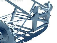
Rear Suspension 3D Model
... suspension 3d model
3dexport
rear suspension spring sport car disc brake chasis
rear suspension 3d model bayazoff 30675 3dexport
turbosquid
$20

Rear sport wheel
...del rear sport wheel for download as ige, obj, stl, and sldas on turbosquid: 3d models for games, architecture, videos. (1227527)
turbosquid
$99
Rear tyre set
... available on turbo squid, the world's leading provider of digital 3d models for visualization, films, television, and games.
turbosquid
$49
Wet Rear tyre
... available on turbo squid, the world's leading provider of digital 3d models for visualization, films, television, and games.
turbosquid
$49
Hard rear tyre
... available on turbo squid, the world's leading provider of digital 3d models for visualization, films, television, and games.
turbosquid
$49
Medium Rear tyre
... available on turbo squid, the world's leading provider of digital 3d models for visualization, films, television, and games.
turbosquid
$49

Supersoft Rear tyre
... available on turbo squid, the world's leading provider of digital 3d models for visualization, films, television, and games.
turbosquid
$39
tractor rim rear
... available on turbo squid, the world's leading provider of digital 3d models for visualization, films, television, and games.