Thingiverse
MPSM Fully Adjustable Z Spacer (MP Select Mini) by wileykyoto
by Thingiverse
Last crawled date: 3 years ago
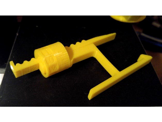
Fully Adjustable Z Spacer
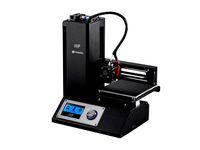
MP Select Mini
By Wiley Kyoto
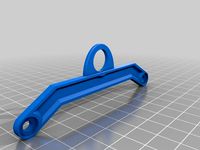
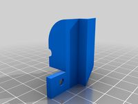
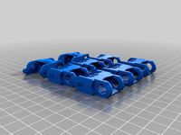
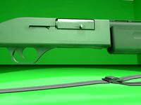
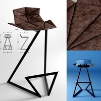
This Z spacer is designed to give you continuous adjustment from 1mm to 5mm. If you want to switch between the stock bed and glass bed, you don't have to adjust your print bed and then re-level it. If the beds already level, just adjust the spacer for the change in height to account for the glass thickness. Also If you change nozzles, the new one might be slightly longer or shorter, so just adjust the Z offset accordingly. I gave the Bracket a slight bend so it keeps constant pressure to hold it firmly in place.
My Print Setup:
PLA
210/60C
No Supports
0.175mm Layer Height
1.4mm Wall Thickness
1.05mm Top and Bottom Thickness
Orientation - Lay the AdjArm and Bracket flat on their sides. Put the AdjDial on one of the flat ends (I had numbers near the top).
Assembly:
Put the AdjDial on the Bracket, in the groove next to the indicator mark, with the numbers closest to the outside edge.
Insert the sloped edge of the AdjArm through the AdjDial, with the threads of the AdjArm facing away from the Bracket.
Keep pressure pushing the AdjArm into the AdjDial as you start to turn the AdjDial clockwise. Keeping in mind that the thread is reversed thread, such that turning the AdjDial clockwise will wind the AdjArm farther in.
Set the AdjDial to roughly the right spot (See Reading the Dial).
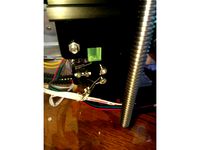
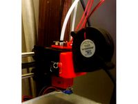
Make sure the head position of the printer is a good couple centimetres in the +Z direction, to prevent damage to the Z limit switch.
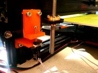
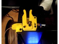
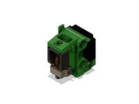
Insert the assembled spacer through the vertical slot in the back of the printer tower, snapping it into place on the Z Bearing Block(Black Plastic Block with metal rods running vertically through it), which you can see through the vertical slot. You should hear and feel a solid click as it snaps securely into place, pushing forward firmly on the top lever of the spacer should help it snap into place.
Make final adjustments the the AdjDial but homing the printer and checking the fit with a piece of paper under the nozzle.
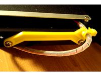
Reading the Dial:
Note - the readings won't have absolute accuracy as it depends on the exact placement of the Z Limit switch, but the relative accuracy should be great.
The AdjArm has 4 notches, with numbers 1 to 4 next to them. These represent whole mm steps.
The AdjDial has 40 notches, every 4 notches are numbered .0 through .9. These represent decimal mm steps. Each notch is a 0.025mm step.
The Bracket has one indicator notch which lines up with the notches on the AdjDial to indicate where to read the setting.
When the outside edge of the Bracket is lined up with the first notch(next to the 1) on the AdjArm and the .0 setting on the AdjDial is centred on the indicator notch, the spacer is set to 1.0mm.
When the AdjArm is all the way into the AdjDial, and the AdjDial is set to .0, the spacer is set to 5.0mm.
The spacer can be set less than 1mm but at some point (around 0.7mm on my printer) the limit switch will slip off the end of the spacer and effectively act as 0mm offset.
MP Select Mini
By Wiley Kyoto
This Z spacer is designed to give you continuous adjustment from 1mm to 5mm. If you want to switch between the stock bed and glass bed, you don't have to adjust your print bed and then re-level it. If the beds already level, just adjust the spacer for the change in height to account for the glass thickness. Also If you change nozzles, the new one might be slightly longer or shorter, so just adjust the Z offset accordingly. I gave the Bracket a slight bend so it keeps constant pressure to hold it firmly in place.
My Print Setup:
PLA
210/60C
No Supports
0.175mm Layer Height
1.4mm Wall Thickness
1.05mm Top and Bottom Thickness
Orientation - Lay the AdjArm and Bracket flat on their sides. Put the AdjDial on one of the flat ends (I had numbers near the top).
Assembly:
Put the AdjDial on the Bracket, in the groove next to the indicator mark, with the numbers closest to the outside edge.
Insert the sloped edge of the AdjArm through the AdjDial, with the threads of the AdjArm facing away from the Bracket.
Keep pressure pushing the AdjArm into the AdjDial as you start to turn the AdjDial clockwise. Keeping in mind that the thread is reversed thread, such that turning the AdjDial clockwise will wind the AdjArm farther in.
Set the AdjDial to roughly the right spot (See Reading the Dial).
Make sure the head position of the printer is a good couple centimetres in the +Z direction, to prevent damage to the Z limit switch.
Insert the assembled spacer through the vertical slot in the back of the printer tower, snapping it into place on the Z Bearing Block(Black Plastic Block with metal rods running vertically through it), which you can see through the vertical slot. You should hear and feel a solid click as it snaps securely into place, pushing forward firmly on the top lever of the spacer should help it snap into place.
Make final adjustments the the AdjDial but homing the printer and checking the fit with a piece of paper under the nozzle.
Reading the Dial:
Note - the readings won't have absolute accuracy as it depends on the exact placement of the Z Limit switch, but the relative accuracy should be great.
The AdjArm has 4 notches, with numbers 1 to 4 next to them. These represent whole mm steps.
The AdjDial has 40 notches, every 4 notches are numbered .0 through .9. These represent decimal mm steps. Each notch is a 0.025mm step.
The Bracket has one indicator notch which lines up with the notches on the AdjDial to indicate where to read the setting.
When the outside edge of the Bracket is lined up with the first notch(next to the 1) on the AdjArm and the .0 setting on the AdjDial is centred on the indicator notch, the spacer is set to 1.0mm.
When the AdjArm is all the way into the AdjDial, and the AdjDial is set to .0, the spacer is set to 5.0mm.
The spacer can be set less than 1mm but at some point (around 0.7mm on my printer) the limit switch will slip off the end of the spacer and effectively act as 0mm offset.
Similar models
thingiverse
free

MP Mini X-Axis Limit Switch Bracket by kapakahi
...emoved the x-axis shroud/guard you are going to need this bracket to keep the limit switch in place.
for monoprice select mini.
thingiverse
free
Tevo Tarantula Z-stop for glass bed by waimeai
...ng the z stop limit switch. adding this u-spacer can compensate for the glass thickness, and the z switch does not have to move.
thingiverse
free

Tronxy P802E adjustable Z limit switch bracket by shadowtrk
...tronxy p802e adjustable z limit switch bracket by shadowtrk
thingiverse
adjustable z limit switch bracket for the tronxy p802e
thingiverse
free

Anet A8 Z Limit Switch Bracket by TheHomeMAK3R
...bracket by thehomemak3r
thingiverse
anet a8 z limit switch bracket/brace to help keep your z-limit switch at the correct height.
thingiverse
free

Dial Indicator Holder for A8 by HollWaz
... possible.
this works best if you set the z height to roughly the middle of the indicators range so it can show + and - readings.
thingiverse
free

Sapphire Pro Improved Z Limit Switch Mount by cluberic
...1/2/3/5mm spacer - spaces in case your nozzle is larger than the stock nozzle and you need the bed to be farther from the hotend.
thingiverse
free

Monoprice MP Select Mini Z Axis Adjustable Endstop by divide
...o keep the spring from binding on the head of the screw.
reused:
limit switch m2 screws and nuts
x carriage shield plastic screw
thingiverse
free

Glass (mirror) Z axis limit switch spacer by DennyNC
... axis limit switch spacer by dennync
thingiverse
simple spacer for z axis offset if you did glass(mirror) mod.
for ctc printers
thingiverse
free

X and Y Limit Switch Spacers - JGAurora A-3 by Helichael
...usable space along the right and rear portions of the bed.
the potential to print in the air to the left and in front of the bed.
thingiverse
free
TEVO Tarantula Z axis limit switch adjustable bracket V2.0 by Todd_Optional
...this part is simple an adjustable z axis limit switch bracket and a upper bracket that holds a screw for simple level adjustment.
Wileykyoto
thingiverse
free

Snowflake Ornaments by wileykyoto
...s here:christmas bauble ornamentsfractal tree ornaments
i hope you enjoy making these for your loved ones.
merry xmas
wiley kyoto
thingiverse
free
MPSM Wire Brace by wileykyoto
...ll do just fine.
update 2017-12-14
added a version with the wire brace centered.
added a version with the wire brace on the left.
thingiverse
free

Extruder base with filament filter by Scanjo
...can either print the rest of the parts from wileykyoto#39;s thing, or modify a metal arm as i...
thingiverse
free
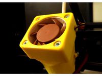
40mm Fan Cover (20mm and 10mm Height) by wileykyoto
...lls. i printed it with a layer height of 0.175mm. i also recommend printing this upside down, so you don't need any supports.
thingiverse
free
MPSM Bed Leveling Utility by wileykyoto
...he beginning. ex "g1 f4800 z1;" sets the feed rate to 4800mm/min before issuing the first move command.
happy printing!
thingiverse
free
Monoprice Select Mini Wire Brace by bradyhuutch
...your makes! the original designs can be found below. wileykyoto https://www.thingiverse.com/thing:2710870 janbbeck:...
thingiverse
free

MPSM V2 Extruder (Outdated See Decription) by wileykyoto
...s:
shout out to robin7331 and his mpsm extruder baseplate v1 for the idea to make a slot for a nut to work with a pc4-m6 fitting.
thingiverse
free
MPSM V2 Improved Extruder (WK9) by wileykyoto
...s:
shout out to robin7331 and his mpsm extruder baseplate v1 for the idea to make a slot for a nut to work with a pc4-m6 fitting.
thingiverse
free
monoprice select mini V2 bowden tube stabilizer
...bowden extruder with mpsm v2 improved extruder (wk9) by wileykyoto and it works great as well as adding capricorn...
Mpsm
thingiverse
free
MPSM Mosquito 2GT
... mosquito 2gt
thingiverse
my adaptation of the mosquito to the mpsm.
printed in petg
1/12/20 added 4010 blower mounting and duct
thingiverse
free
MPSM E3D mount by tekhertz
...mpsm e3d mount by tekhertz
thingiverse
just another e3d mount, fits into original carriage on mpsm v1
thingiverse
free

Best MPSM Post Caitlin by Dr_Joel
...best mpsm post caitlin by dr_joel
thingiverse
for most charming post on the facebook mpsm group.
thingiverse
free

Santa and Sleigh Spinner for MPSM by itsonlym3
...santa and sleigh spinner for mpsm by itsonlym3
thingiverse
topper/spinner for the mpsm and just in time for christmas. ;-)
thingiverse
free

MPSM Vent and single fan by Quadfather818
...and single fan by quadfather818
thingiverse
moved fan from back of mpsm-v2 for heat bed rewire and added to passive cooling vent
thingiverse
free
Cube Spinner MPSM by oxamo
...cube spinner mpsm by oxamo
thingiverse
a spinner for the extruder wheel.
thingiverse
free

MPSM Bowden Clip by Rico_3D
...mpsm bowden clip by rico_3d
thingiverse
for hot end and extruder
thingiverse
free
MPSM Bed Rewiring Parts
...mpsm bed rewiring parts
thingiverse
3d printer parts.
thingiverse
free

Gyro Spinner For MPSM by itsonlym3
...gyro spinner for mpsm by itsonlym3
thingiverse
topper/spinner for your extruder.https://youtu.be/swbjup3tcym
thingiverse
free
MPSM Blower - no part duct by jbkuma
...sm that fits stock carriage. no part cooler. i use a separate $9 clip fan for part cooling that is dead silent and works great.
Mp
turbosquid
$19
MP-5
...-5
turbosquid
royalty free 3d model mp-5 for download as fbx on turbosquid: 3d models for games, architecture, videos. (1537795)
turbosquid
$3

MP-18
...turbosquid
royalty free 3d model mp-18 for download as blend on turbosquid: 3d models for games, architecture, videos. (1506436)
turbosquid
$5

Mp-28
...quid
royalty free 3d model mp-28 for download as fbx and obj on turbosquid: 3d models for games, architecture, videos. (1613220)
turbosquid
$5

Nightstand MP
...yalty free 3d model nightstand mp for download as max and fbx on turbosquid: 3d models for games, architecture, videos. (1655571)
turbosquid
$25

MP 3008
... available on turbo squid, the world's leading provider of digital 3d models for visualization, films, television, and games.
turbosquid
$25

MP 28
... available on turbo squid, the world's leading provider of digital 3d models for visualization, films, television, and games.
turbosquid
$20
MP-44
... available on turbo squid, the world's leading provider of digital 3d models for visualization, films, television, and games.
turbosquid
$20
MP-153
... available on turbo squid, the world's leading provider of digital 3d models for visualization, films, television, and games.
turbosquid
$2

Mp 41
... available on turbo squid, the world's leading provider of digital 3d models for visualization, films, television, and games.
turbosquid
free
MP-44.3ds
... available on turbo squid, the world's leading provider of digital 3d models for visualization, films, television, and games.
Spacer
turbosquid
$55
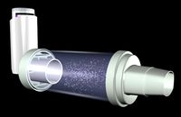
Spacer
... available on turbo squid, the world's leading provider of digital 3d models for visualization, films, television, and games.
turbosquid
$60
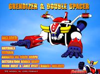
grendizer & double spacer
... available on turbo squid, the world's leading provider of digital 3d models for visualization, films, television, and games.
3d_export
$5
Hex Spacers M3 Male-Female
... spacers m3 male-female
3dexport
hex spacers m3 male-female with length from 5mm to 60mm for printed circuit boards. step files.
3d_export
$5
industrial lift - spacer crane
...crane<br>- 500 kg<br>- render 3ds max 2020 and corona renderer.<br>- formats: max 2020, max 2017, obj, fbx, stp
3d_export
$5

spacer hanging light
...lampshades: any total number of lamps: 6 polys: 18 546 verts: 19 045 https://imperiumloft.ru/lyustry-175/ev_a048924-eurosvet.html
turbosquid
$5
Industrial lift Spacer crane Renaissance construction
...naissance construction for download as max, max, fbx, and obj on turbosquid: 3d models for games, architecture, videos. (1571898)
3d_export
$7

industrial lift - spacer crane renaissance construction
...ction<br>- 750 kg<br>- render 3ds max 2020 and corona renderer.<br>- formats: max 2020, max 2017, obj, fbx, stp
3d_export
$10
Spacer Sliding Wardrobe 1200 Hanger
...painter available for all software<br>ue4. ue5. blender. maya. 3d max. unity. c4d.<br>formats: .obj .gltf .fbx .blend
3d_export
$5
Hockey puck 3D Model
...hockey puck 3d model 3dexport hockey puck spacer washer disk shim hockey puck 3d model gizmo_fbi 28754...
3d_export
$5

Front 30mm Lift Kit for 1996-2004 Nissan Pathfinder and 1997-2003 Infiniti QX4
...terrano r50, regulus 1997-2003 infiniti qx4 - front strut spacer ...
Select
3ddd
$1

TUBADZIN SELECT
...max 2014, 2011.
fbx 2014, 2013, 2011,
obj
_____________________________________http://www.tubadzin.pl/en/collection/324
3ddd
$1
Плитка Selection
... supergres , плитка
плитка selection - supergres ceramiche
turbosquid
$15
Christmas Selection
...royalty free 3d model christmas selection for download as fbx on turbosquid: 3d models for games, architecture, videos. (1696333)
turbosquid
$39

Vases selection
... available on turbo squid, the world's leading provider of digital 3d models for visualization, films, television, and games.
turbosquid
free

SELECTIVE RACKING SYSTEM
...yalty free 3d model selective racking system for download as on turbosquid: 3d models for games, architecture, videos. (1282512)
turbosquid
$10
Hansgrohe ShowerTablet Select
...ee 3d model hansgrohe showertablet select for download as max on turbosquid: 3d models for games, architecture, videos. (1336955)
turbosquid
$29
Chill selectional sofa
...odel chill selectional sofa for download as max, obj, and fbx on turbosquid: 3d models for games, architecture, videos. (1465691)
3ddd
free

Lunaria - Nova, ASA Selection
... asa selection , dried flowers
ветка лунарии в вазе nova, asa selection
3ddd
$1
inno SELECT SLIM chair
...inno select slim chair
3ddd
inno
high detailed inno select slim chair
turbosquid
$29

Select Chaise Lounge
... available on turbo squid, the world's leading provider of digital 3d models for visualization, films, television, and games.
Z
3d_export
$5
nissan z
...nissan z
3dexport
nissan z
3ddd
$1
Vase Z
...vase z
3ddd
vase z
3ddd
$1
полотенцесушить Z
...полотенцесушить z
3ddd
полотенцесушитель
полотенцесушить z
design_connected
free
Z-Chair
...z-chair
designconnected
free 3d model of z-chair designed by karman, aleksei.
design_connected
$11
Z Lamp
...z lamp
designconnected
phillips z lamp computer generated 3d model. designed by kalff, louis.
3d_export
$5
Dragon balls z
...dragon balls z
3dexport
dragon ball z
turbosquid
$20

Fighter Z
...
turbosquid
royalty free 3d model fighter z for download as on turbosquid: 3d models for games, architecture, videos. (1292563)
turbosquid
$9

Pen Z
...pen z
turbosquid
free 3d model pen z for download as obj on turbosquid: 3d models for games, architecture, videos. (1686775)
turbosquid
free
z chair
...z chair
turbosquid
free 3d model z chair for download as max on turbosquid: 3d models for games, architecture, videos. (1410230)
turbosquid
$5

Letter Z
...urbosquid
royalty free 3d model letter z for download as max on turbosquid: 3d models for games, architecture, videos. (1408540)
Mini
turbosquid
$10
Mini Mini Luceplan
...
royalty free 3d model mini mini luceplan for download as max on turbosquid: 3d models for games, architecture, videos. (1227359)
3d_ocean
$39
Mini Cooper
...mini cooper
3docean
cabrioler cooper mini
mini cooper cabrioler
3d_export
$30

Mini lathe
...mini lathe
3dexport
mini lathe
3d_export
$5
mini mouse
...mini mouse
3dexport
mini mouse
3d_export
$5
mini house
...mini house
3dexport
mini house
3d_export
free

Mini Mecha
...mini mecha
3dexport
concept of mini mecha
3d_ocean
$20
Mini Gun
...mini gun
3docean
gatling gun gun machine gun mini gun weapon
model of a mini gatling gun.
3ddd
free
Herve mini
... кофейный , herve
http://www.mobiliavenanti.it/ru/products/hervè-mini
3d_export
$5
mini wall
...mini wall
3dexport
mini wall for living room
3d_export
$5

mini bank
...mini bank
3dexport
mini bank 3d model
Fully
turbosquid
$50

Drone fully rigged
...
royalty free 3d model drone fully rigged for download as max on turbosquid: 3d models for games, architecture, videos. (1282280)
turbosquid
$12
FULLY PARAMETRIC CHAIR
...alty free 3d model fully parametric chair for download as rvt on turbosquid: 3d models for games, architecture, videos. (1280209)
turbosquid
$10

firetruck-fully-rigged
...yalty free 3d model firetruck-fully-rigged for download as ma on turbosquid: 3d models for games, architecture, videos. (1653811)
turbosquid
$6

Fully rigged character
...ty free 3d model fully rigged character for download as blend on turbosquid: 3d models for games, architecture, videos. (1486076)
turbosquid
$3

Fully Rigged shark
...ee 3d model fully rigged 3d shark model for download as blend on turbosquid: 3d models for games, architecture, videos. (1517695)
turbosquid
$75
Fully Customizable Hospital
... available on turbo squid, the world's leading provider of digital 3d models for visualization, films, television, and games.
turbosquid
free
Fully Rigged Link
... available on turbo squid, the world's leading provider of digital 3d models for visualization, films, television, and games.
design_connected
$16

Troy W Fully Covered
...troy w fully covered
designconnected
magis troy w fully covered computer generated 3d model. designed by wanders, marcel.
cg_studio
$99

Pepe fully rigged3d model
...ully rigged3d model
cgstudio
.max - pepe fully rigged 3d model, royalty free license available, instant download after purchase.
3d_export
$60

Ankylosaur 8K - fully animated
...ankylosaur 8k - fully animated
3dexport
Adjustable
3d_ocean
$7
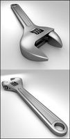
Adjustable Wrench
...adjustable wrench
3docean
adjustable wrench highly detailed wrench
highly detailed adjustable wrench.
3ddd
$1
Adjustable Stool
...adjustable stool
3ddd
табурет
wooden adjustable stool.
3d_ocean
$20

Adjustable Gym Bench
...st adjustable bench black equipement gym gymnastic indoor silver sport workout
3d model of black and silver adjustable gym bench.
3d_ocean
$20
Adjustable Gym Bench
...st adjustable bench black equipement gym gymnastic indoor silver sport workout
3d model of black and silver adjustable gym bench.
3d_ocean
$16

Adjustable Weight Bench
...arbell bench black equipement gym gymnastic indoor sport weight workout
3d model of black adjustable weight bench with a barbell.
turbosquid
$5

Adjustable wrench
...
royalty free 3d model adjustable wrench for download as fbx on turbosquid: 3d models for games, architecture, videos. (1313414)
3d_export
$5
adjustable tension lock
...adjustable tension lock
3dexport
adjustable tension lock
turbosquid
$1

Adjustable Wrench
...free 3d model adjustable wrench for download as obj and blend on turbosquid: 3d models for games, architecture, videos. (1446736)
turbosquid
$1

Adjustable Wrench
...y free 3d model adjustable wrench for download as c4d and fbx on turbosquid: 3d models for games, architecture, videos. (1379022)
3d_export
$5
Adjustable key
...adjustable key
3dexport