GrabCAD
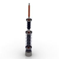
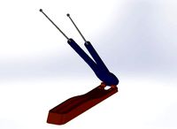
2m Amateur Radio Halo Omni-Directional Antenna
by GrabCAD
Last crawled date: 1 year, 11 months ago
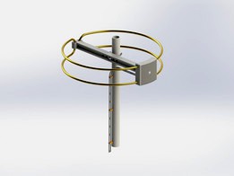
This is a model of a 2m Amateur Radio Halo Omni-Directional Antenna that i designed after a commercially available one wherein i made modifications to remove all ferrous materials to help improve the performance of the antenna.
https://www.amazon.com/FM-Loop-Antenna-Outdoor-Attic-mount/dp/B006SLV25C/ref=asc_df_B006SLV25C/
I also chose NOT to use coax and use a 300 ohm twin ladder line instead. The particular one i used has a larger gauge wire as 18 AWG instead of the typical 20 or 22 AWG and is a 'window' type that reduces the dielectric losses by the cutouts. Typical loss of "type RG-58 coaxial cable loses 6.6 dB per 100 m at 30 MHz, while 300 ohm twin-lead loses only 0.55 dB" (https://en.wikipedia.org/wiki/Twin-lead).
High quality 18 AWG 300 ohm twin-leand cable is available from the 'wireman' : https://thewireman.com/product/18-awg-300ohm-stranded-window-line/#iLightbox[]/0
The halo antenna is basically a folded dipole that is wrapped in a cylindrical shape which is useful for cars, RVs, boats, or other areas where a smaller antenna does well. Since the folded dipole is 4x the impedance of the dipole antenna @ 74 ohms x 4 = 292 ohms ~ 300 ohms, which is what the twin-lead feed line is, so a matching network is not local to the antenna in the NEAR field, but a 300:50 or 6:1 balun should be used close to the ground level. https://en.wikipedia.org/wiki/Dipole_antenna#Folded_dipole
The elements are 1/4" (6mm) aluminum tubing. I choose a gold anodizing passivation for the color.
Design note : there are only (2) fasteners for the assembly : (1) 6mm or 1/4" carriage bolt with a nylock nut and (1) 4mm rounded nylon screw. The carriage bolt can be nylon (if available) or aluminum as well as the nut. I specifically choose NOT to use steel (iron) based fasteners as they will detune the antenna and re-shape the radiation pattern.
Design note : the use of twin-lead reduces line losses *significantly*, however the transition to coax must be done at least 12" (1 foot or 1/3 meter) above Earth ground, otherwise ground coupling will incur losses to the twin-lead cable. A 300:50 or 6:1 Bal-Un (balanced twin lead to unbalanced coax) is required here. There is no issue with coax laying on the Earth ground and in fact it may reduce EMI issues on the outside of the coax better than other choke and magnetic methods. And the coax can also be buried into the earth ground as well !
There are (3) 3D printed parts :
(1) beam support
(1) access cover
(12++) twin feed line standoffs
All of these being 3D printed in a non-conductive material will also help performance.
Halo antennas come in other shapes with a split single loop being the most common :
https://en.wikipedia.org/wiki/Halo_antenna
However NX7U has a 3-coil design that's worth taking a look at :
https://www.nx7u.net/HiPar.html
Similar models
grabcad
free

450 Ohm Impedance Ladder Line Antenna Cable
...k to the manufacturer is here and they also sell wire dipole cable supports too ! :
https://www.wimo.com/en/parallel-wire-450-ohm
grabcad
free

450 Ohm Impedance Ladder Line Antenna Cable
...ine away from metal objects.
this type of wire is also affected by earth ground and should not be run close or along the ground.
grabcad
free

2m Amateur Radio Cycloid Omni-Directional Antenna
...wire feed from a balun lower down the mast similar to the feed method that i used in the...
3dwarehouse
free

3D Printable case for old TV set antenna plug
...se
i made this case in order to build a male plug for a 300 ohm twin lead antenna line to be connected to an old vhf tv receiver
thingiverse
free
Coax Dipole Antenna Enclosure by ka9etc
...provides an alternative to a pvc pipe enclosure or similar when installing a coax dipole outdoors. the structure keeps...
grabcad
free

2m Slot-Cube Amateur Radio Omni-Directional Antenna
...www.w6nbc.com/
lastly there is a video on youtube about creating this style of antenna :
https://fuzzthepiguy.tech/cube-antenna/
grabcad
free

23cm Amateur Band EME Septum Feed Antenna Aperture
... than a casagrain / gregorian configuration, but may be used for either as well : https://en.wikipedia.org/wiki/parabolic_antenna
thingiverse
free

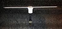
Dipole antenna center T-case by DzikuVx
...tubes, but will fit all cables and tubes with similar diameter. you need 2 elements for one...
thingiverse
free

1/4 Wave Ground Plane Antenna Mk II by _HAZMAT
...ax cable, than a 45 degree tilt
improved rigidity
my specific instance of this object was designed for the 2m amateur radio band.
thingiverse
free
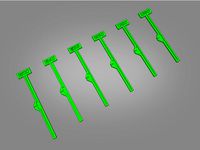
Dipole Antenna Jig 1.2-1.3GHz by StuntDouble
...e or even 24 awg silicon wire.
there are 6 of the common 1.2-1.3ghz frequencies to choose from: 1200/1240/1258/1280/1320/1360 mhz
Omni
turbosquid
$10

Omni Wheel
...turbosquid
royalty free 3d model omni wheel for download as on turbosquid: 3d models for games, architecture, videos. (1632961)
turbosquid
$89

Omni Armchair
... available on turbo squid, the world's leading provider of digital 3d models for visualization, films, television, and games.
turbosquid
$79

Omni Bench
... available on turbo squid, the world's leading provider of digital 3d models for visualization, films, television, and games.
turbosquid
$69

Omni Chair
... available on turbo squid, the world's leading provider of digital 3d models for visualization, films, television, and games.
turbosquid
$10

Omni King
... available on turbo squid, the world's leading provider of digital 3d models for visualization, films, television, and games.
turbosquid
$9

OMNI CHAIR
... model omni chair for download as max, max, 3ds, fbx, and obj on turbosquid: 3d models for games, architecture, videos. (1644795)
3ddd
$1

Materia - Omni
...oak top, complement the armchair perfectly, making omni a modern and elegant, eye-catching feature in hotels and reception areas.
turbosquid
$9

Omni black coin
...id
royalty free 3d model omni black coin for download as max on turbosquid: 3d models for games, architecture, videos. (1499436)
turbosquid
$9

Omni gold coin
...uid
royalty free 3d model omni gold coin for download as max on turbosquid: 3d models for games, architecture, videos. (1499434)
turbosquid
$9

Omni Techo chair
...e 3d model omni techo chair for download as max, obj, and fbx on turbosquid: 3d models for games, architecture, videos. (1528704)
Amateur
3d_export
$30

Amateur Leather Dress
...amateur leather dress
3dexport
amateur leather dress
turbosquid
$3

Pistol Amateur Model
...oyalty free 3d model pistol amateur model for download as max on turbosquid: 3d models for games, architecture, videos. (1299726)
3d_export
$5

Beretta 92FS 9mm
...beretta 92fs 9mm 3dexport a pistol made by an amateur modeler. can be used as a static...
3d_export
$6

MercedesEW124Cabriolet1985
...mercedesew124cabriolet1985 3dexport amateur high poly 3d model. there are both squares and...
3d_export
$15
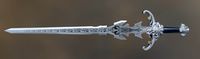
fantasy sword 3d
...fantasy sword 3d 3dexport my another amateur try :) . it took my 5 hours ......
3d_export
$70

Ten Tec Eagle Transceiver 3D Model
...transceiver 3d model 3dexport ten tec eagle transceiver ham amateur radio communication reciever transmit talk cb citizens band ssb...
3ddd
$1
Паук-гнилец / rotten-spider
...model of the rotten-spider. this model was made for amateur game project. polycount - 55k triangles. archive contains textures...
3d_export
$149

AV-1 helicopter
...designed and built by<br>in the garage by a self-taught amateur vasily artemchuk from ukraine in the 90s.<br>the helicopter was...
3d_export
$90

extreme raptor collection - 8k
...this one really resembles the one in the movies.<br>these amateur models mimic the animals we see in movies, but...
3d_sky
free

Amateur 166
...amateur 166
3dsky
camera
soviet medium format twin-lens reflex camera simplified type.
2M
turbosquid
$15
Camera Chaika 2M
...d
royalty free 3d model camera chaika 2m for download as max on turbosquid: 3d models for games, architecture, videos. (1328666)
turbosquid
$17
Swing 2m Hardwood
... 3d model swing 2m hardwood for download as max, fbx, and obj on turbosquid: 3d models for games, architecture, videos. (1630788)
turbosquid
$79

Creative Booth Design Template 4m * 4m - 3m * 3m - 2m * 2m
... available on turbo squid, the world's leading provider of digital 3d models for visualization, films, television, and games.
turbosquid
$10

Helmet ZSH 1-2M
...ee 3d model helmet zsh 1-2m for download as obj, fbx, and dae on turbosquid: 3d models for games, architecture, videos. (1330777)
humster3d
$75

3D model of SR-2M Veresk
...
buy a detailed 3d model of sr-2m veresk in various file formats. all our 3d models were created maximally close to the original.
turbosquid
$29

Concrete Fence Panel PO-2M
...po-2m for download as blend, unitypackage, fbx, obj, and gltf on turbosquid: 3d models for games, architecture, videos. (1712966)
turbosquid
$20

Norway Maple (Acer platanoides) 2m
...er platanoides) 2m for download as ma, max, obj, c4d, and fbx on turbosquid: 3d models for games, architecture, videos. (1175968)
turbosquid
$49

Kiosk Exhibition Stand Project 3m x 2m
...ition stand project 3m x 2m for download as obj, c4d, and fbx on turbosquid: 3d models for games, architecture, videos. (1322108)
turbosquid
$39

Kiosk Expo Stand Display 2m x 3m
... expo stand display 2m x 3m for download as obj, c4d, and fbx on turbosquid: 3d models for games, architecture, videos. (1322389)
turbosquid
$29

Kiosk Exhibition Counter Stand 2m x 3m
...ition counter stand 2m x 3m for download as obj, c4d, and fbx on turbosquid: 3d models for games, architecture, videos. (1323971)
Radio
archibase_planet
free
Radio
...radio
archibase planet
radio
radio - 3d model for interior 3d visualization.
archibase_planet
free
Radio
...radio
archibase planet
radio
radio - 3d model for interior 3d visualization.
3d_export
$10
radio
...radio
3dexport
radio 3d, ojb
archibase_planet
free

Radio
...radio
archibase planet
radio set wireless receiver wireless set
radio 2 - 3d model (*.gsm+*.3ds) for interior 3d visualization.
archibase_planet
free
Radio
...radio
archibase planet
radio set wireless receiver wireless set
radio 7 - 3d model (*.gsm+*.3ds) for interior 3d visualization.
archibase_planet
free
Radio
...radio
archibase planet
radio set wireless receiver wireless set
radio 10 - 3d model (*.gsm+*.3ds) for interior 3d visualization.
3d_ocean
$9
Vintage Radio
...vintage radio
3docean
old radio radio set vintage
this is a vintage radio modeled to help in interior design arrangements.
3d_ocean
$8
Radio Branu
...radio branu
3docean
detail radio vintage
vintage radio with detail
3d_export
$5

radio
...radio
3dexport
turbosquid
$25

Radio
...o
turbosquid
royalty free 3d model radio for download as max on turbosquid: 3d models for games, architecture, videos. (1203794)
Antenna
archibase_planet
free
Antenna
...chibase planet
antenna aerial television antenna
antenna kathrein n090913 - 3d model (*.gsm+*.3ds) for exterior 3d visualization.
archibase_planet
free
Antenna
...antenna
archibase planet
satellite antenna
antenna 1 - 3d model (*.gsm+*.3ds) for exterior 3d visualization.
archibase_planet
free
Antenna
...antenna
archibase planet
equipment satellite antenna
antenna 2 - 3d model (*.gsm+*.3ds) for exterior 3d visualization.
archibase_planet
free
Antenna
...ntenna
archibase planet
satellite antenna equipment dish aerial
antenna 3 - 3d model (*.gsm+*.3ds) for exterior 3d visualization.
archibase_planet
free
Antenna
...antenna
archibase planet
satellite antenna dish dish aerial
antenna 4 - 3d model (*.gsm+*.3ds) for exterior 3d visualization.
archibase_planet
free
Antenna
...e planet
antenna dish dish aerial
antenna c-band satellite s180-g n210612 - 3d model (*.gsm+*.3ds) for exterior 3d visualization.
3d_export
$5
car antenna
...car antenna
3dexport
car antenna, antenna, car gadgets
turbosquid
$1

antenna
...rbosquid
royalty free 3d model antenna for download as blend on turbosquid: 3d models for games, architecture, videos. (1655786)
3d_export
free

Station with antenna
...station with antenna
3dexport
station with antenna
turbosquid
$5

Antenna
...id
royalty free 3d model antenna for download as max and fbx on turbosquid: 3d models for games, architecture, videos. (1381532)
Halo
3ddd
$1

Halo
...halo
3ddd
halo
бра,диаметр 46см,
3ddd
$1

Vibia / Halo
...vibia / halo
3ddd
vibia
подвес halo от vibia
turbosquid
$5

Halo
... available on turbo squid, the world's leading provider of digital 3d models for visualization, films, television, and games.
3ddd
$1

Halo - Professor
...halo - professor
3ddd
halo
http://homeconcept.ru/catalog/section.php?section_id=18998#tab_0_0
3ddd
free

Artifort Halo
...t halo
3ddd
halo , artifort
в архиве max 2014 / fbx
чертеж с размерами на 3 изображении.
3ddd
$1

Halo Huntington
...--------------------------------------
polygons: 520605
vertices: 525856
единицы измерения - real world size (system units - mm)
3ddd
$1
Halo
...r
l 125 d 87 h 109 sh 39 cm
sofa
l 242 d 87 h 109 sh 39 cm
designer
skrivo
year of design: 2015http://www.softline.dk
turbosquid
$3

HALO RING
...rbosquid
royalty free 3d model halo ring for download as stl on turbosquid: 3d models for games, architecture, videos. (1355249)
turbosquid
$5

Artemide - Halo
...lty free 3d model artemide - halo for download as max and obj on turbosquid: 3d models for games, architecture, videos. (1159228)
3ddd
$1
Artemide CLS Halo
...artemide cls halo
3ddd
artemide
artemide cosmic leaf soffitto halo
Directional
design_connected
free

Compas Direction
...compas direction
designconnected
free 3d model of compas direction by vitra designed by prouvé, jean.
design_connected
$18

Direction Pivotant
...direction pivotant
designconnected
vitra direction pivotant computer generated 3d model. designed by prouvé, jean.
turbosquid
$6
not direct the front
...oyalty free 3d model not direct the front for download as max on turbosquid: 3d models for games, architecture, videos. (1213034)
turbosquid
$10

Rails Direct
... available on turbo squid, the world's leading provider of digital 3d models for visualization, films, television, and games.
3d_export
$5

Picto toilet directions
...lude 3d files next to rhino6: x3dv, step, igus, obj and stl. double-sided, flipping changes the gender directions to the toilets.
3ddd
$1
fauteuli direction
...d
chair , vitra , fauteuli
fauteuli vitra chair
design_connected
$18

Fauteuil Direction, 1951
...fauteuil direction, 1951
designconnected
vitra fauteuil direction, 1951 computer generated 3d model. designed by prouvé, jean.
3d_export
$5
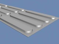
Directional tactile 3D Model
...tactile 3d model
3dexport
directional tactile braille tile flooring interior
directional tactile 3d model renob000 71068 3dexport
turbosquid
$26

Radio direction finder A
...ty free 3d model radio direction finder a for download as fbx on turbosquid: 3d models for games, architecture, videos. (1212490)
turbosquid
$7

Wooden direction signage
...ty free 3d model wooden direction signage for download as max on turbosquid: 3d models for games, architecture, videos. (1453747)