Thingiverse

Z-axis_linear_rails_MGN12H by Far_a_way
by Thingiverse
Last crawled date: 3 years, 1 month ago
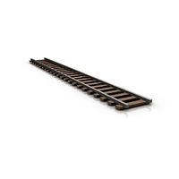
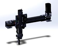
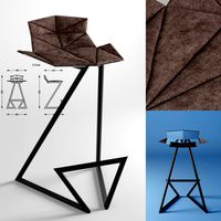
Conversion of the Z-axis with linear rails MGN12H
Anet E10 MGN12H; 300mm lg
Anet E12 MGN12H; 400mm lg
As part of the renovation, I moved the extruder motor upwards so that one
Filament change the Z-axis can no longer be accidentally adjusted.
For the extruder motor mount above you need a ball bearing 688ZZ (8x16x5mm), which is pressed in.
For people who do not want this, I have also provided a solution.
Print required components, I printed my parts with 15% support. The X-axis motor mount
was printed with 60% infill, the other parts only with 30% infill.
The Z-axis conversion can be used with original X-carriages and when converting to MGN12 linear rails, followed by a conversion of the X-axis to beltless.
After printing out the required components, the X-carriage must be dismantled. It is best to start with the right side, where there is no motor bracket, as follows, move the Z-axis as high as possible, dismantle the X-axis, dismantle the Z-slide on the right-hand side, dismantle the trapezoidal thread spindle guide at the top right, trapezoidal thread nut as well Place the new component, mount the linear rail with the fixed carriage (!! fix otherwise the balls will fall out of the guide), I have attached the linear rail at the top so that the air gap remains at the bottom, screw the printed Z-axis guide onto the threaded spindle and fix it with 4 screws M3x6mm on the linear rail carriage. Place the X-axis loosely between the Z-axis carriages (1 screw on each side), Carefully lower the Z-axis and only screw the X-axis down at the bottom, so the distance between the Z-spindles is not adjusted much. Move the Z-axis back up and only now screw on the loose threaded spindle guide on top. The same is done on the left-hand side, but before the X-axis is set here, the X-axis motor mount is attached to the stop on the X-axis. If you now push the fastening strap of the motor bracket to the linear rail carriage, the X-axis limit switch is back in its original position.
There is an M3 threaded opening on the underside of the X-axis motor bracket, where a M3x20 flat head screw can be used as a stop adjustment.
If necessary, extend the cable and tube.
Reattach the dismantled components of the X-axis, lower the X-axis and adjust.
Similar models
thingiverse
free

Tronxy X5SA linear guides by Far_a_way
... the y-limit switch, print out the modified retaining bracket, dismantle the limit switch, relocate and reassemble on the inside.
3dwarehouse
free

SolidCore CoreXY Y-Carriage Assembly
...y carriage and z-axis. the y-axis assembly components mount to a mgn12h linear rail. https://3ddistributed.com/corexy-3d-printer/
thingiverse
free

X-Z axis plate -right side - with DC motor mount by unix_guru
...ount by unix_guru
thingiverse
right side x/z axis plate to mount z-axis linear bearings, x-axis rods, and x-axis dc servo motor.
thingiverse
free

Tevo Tarantula Z-Axis MGN12 Rail Brackets/Mounts by evil_k
...
you will need to change the belt drive for the x-axis. the parts i used are on thingiverse. check the tevo tarantula collection.
thingiverse
free

Dual Z axis MGN12H linear rails kit Print parts by HoganZeng
... reduces the z-axis layer pattern, offset, and distortion of higher models, and improves the surface effect of the printed model.
thingiverse
free

Y-Axis Linear Bearing Mod MGN12H for Ender 3 V2 by ngungbi
... then tighten the rail screw at the rear.
make sure the carriage can move freely with very little resistance.
reassemble the bed.
grabcad
free

tevo tarantula aluminum parts all axis linear rail.
... parts all axis linear rail.
grabcad
the axis has mgn12h rail
the z axis has mgn12h rail (dual z axis)
the x axis has mgn9c rail
thingiverse
free

Carriage for MGN12H and Bondtech BMG by 3ddruckqueck
...e carriage has lots of mounting points designed to take cheap 4mm x 3mm m3 bronze inserts.
i included a bltouch mounting bracket.
thingiverse
free

BD's Tarantula Z Motor and Nut Mounts by bdwalker1
... print bed. it moves things far enough back to allow the x-axis carriage to pass between the lead screw and the x-axis extrusion.
thingiverse
free

Dremel CNC X-carriage redesign by mgreven
...er than the original design to mount it to the mgn12 sliding block and the moter of the z-axis is mounted on top of the carriage.
Mgn12H
thingiverse
free

Mount 775 motor mgn12h by crazysova
...mount 775 motor mgn12h by crazysova
thingiverse
mount 775 motor mgn12h
thingiverse
free

Servo mount for MGN12H rail by Kieranod
...servo mount for mgn12h rail by kieranod
thingiverse
servo mount for mgn12h rail
thingiverse
free

MGN12H Titan Mount Vfire by 3DPrintingEverything
...mgn12h titan mount vfire by 3dprintingeverything
thingiverse
mgn12h mount for a titan e3d extuder
thingiverse
free

Kossel Mini carriage for MGN12H by gnahz
...kossel mini carriage for mgn12h by gnahz
thingiverse
kossel mini carriage for mgn12h with end stop
thingiverse
free

Tarantula Y carriage for MGN12H by ikong
...tarantula y carriage for mgn12h by ikong
thingiverse
tevo tarantula y carriage for mgn12h (of mgn12 rail).
thingiverse
free

MGN12H clamping V-slot by SviatoslavWolf
...mgn12h clamping v-slot by sviatoslavwolf
thingiverse
создал крепление для напрявляющих mgn12h под профиль v-slot
thingiverse
free

MGN12H aero p3steel v18 campy by maskeperro
...eperro
thingiverse
mgn12h aero p3steel v18 campy , pieza modificada para usar con mgn12h ....la original de campy es para mgn12c
thingiverse
free

MGN12H to 2020 and belt holder for x Axis by Kieranod
...epper.
mgn12h without belts.stl has no belt i used it on the side of the nema17 stepper.https://www.thingiverse.com/thing:2959042
thingiverse
free

MGN12C and MGN12H adapter plate by 3r4th
...h
thingiverse
i created a adapter plate for the y axis from mgn12c and mgn12h to a hole pattern of the sc8uu.
best regards 3r4th
thingiverse
free

MGN12H linear rail 20x20 adapter by Goretec
... linear rail 20x20 adapter by goretec
thingiverse
mgn12h linear rail adapter for mounting 20x20 extrusion to the linear guide.
Linear
3ddd
$1
Linear Diffusers
...linear diffusers
3ddd
диффузор
set of linear diffusers for ceiling.
design_connected
$27
Linear Sofa
...linear sofa
designconnected
scp linear sofa computer generated 3d model.
design_connected
$18

Atlantis linear
...atlantis linear
designconnected
terzani atlantis linear pendant lights computer generated 3d model. designed by barlas baylar.
3d_export
$5
light linear unit
...light linear unit
3dexport
light linear unit
turbosquid
$5
Linear Actuator
...
royalty free 3d model linear actuator for download as blend on turbosquid: 3d models for games, architecture, videos. (1589061)
turbosquid
$29
Linear panel
...oyalty free 3d model linear panel for download as max and obj on turbosquid: 3d models for games, architecture, videos. (1391254)
turbosquid
$12
Linear Chandelier
...y free 3d model linear chandelier for download as max and obj on turbosquid: 3d models for games, architecture, videos. (1574289)
turbosquid
$10

Linear Axis
... available on turbo squid, the world's leading provider of digital 3d models for visualization, films, television, and games.
turbosquid
$10

Grohe Lineare
... available on turbo squid, the world's leading provider of digital 3d models for visualization, films, television, and games.
3d_export
$5

Linear Unit 3D Model
...linear unit 3d model
3dexport
linear unit force torque velocity
linear unit 3d model fau 71218 3dexport
Far
3d_export
$10

far west buildings
...far west buildings
3dexport
some far west buildings like saloon, sheriff office...
3ddd
free

Bellavista - Dolce far niente pleated
... dolce , банкетка
bellavista - dolce far niente pleated
turbosquid
$9

Chandra rugs FAR-6207
... available on turbo squid, the world's leading provider of digital 3d models for visualization, films, television, and games.
3d_export
free

water collector far art-3822-3412tp bonus
...le includes next models:<br>1) water collector far art-3822-3412tp<br>2) metal bracket with fasteners far.art-7480-34
3d_export
$5

mysterio - spdierman far from home
...from home
3dexport
excellent for small size 3d printing.<br>simple sketchup modeling.<br>ideal model for papercraft.
3d_export
$5

spiderman - spiderman far from home
...from home
3dexport
excellent for small size 3d printing.<br>simple sketchup modeling.<br>ideal model for papercraft.
turbosquid
free

Water Collector FAR Art-3822-3412TP plus Bonus
...ollector far art-3822-3412tp plus bonus for download as blend on turbosquid: 3d models for games, architecture, videos. (1639022)
3d_export
$41

Iranian Khalij Fars Cruise Missile 3D Model
...range up to 300km.nose fins designed for animations.2048x2048 texture map & bump map provided.1024x1024 texture maps for fins
3d_export
$5

spiderman stealth suit - spiderman far from home
...from home
3dexport
excellent for small size 3d printing.<br>simple sketchup modeling.<br>ideal model for papercraft.
3d_export
$40

R2D2 Star Wars
...a plucky little astromech droid from a galaxy far, far away. he is an ally to the rebel alliance,...
Rails
3d_ocean
$5
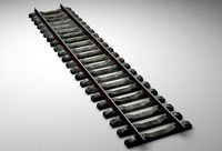
rails
...rails
3docean
old rails rails sleepers
old rails
archibase_planet
free
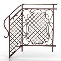
Rail
...chibase planet
rail railing handrail guard-rail
rail forged fence n310814 - 3d model (*.gsm+*.3ds) for exterior 3d visualization.
archibase_planet
free

Rail
...rail
archibase planet
handrail railing guard-rail
rail n220914 - 3d model (*.gsm+*.3ds) for interior 3d visualization.
archibase_planet
free

Rail
...rail
archibase planet
railing hand-rail banisters
rail n130309 - 3d model (*.gsm+*.3ds) for interior 3d visualization.
archibase_planet
free
Rail
...rail
archibase planet
railing hand-rail banisters
rail n270510 - 3d model (*.gsm+*.3ds) for interior 3d visualization.
archibase_planet
free
Railing
...
archibase planet
railing handrail fence guard-rail
railing n140314 - 3d model (*.gsm+*.3ds+*.max) for exterior 3d visualization.
archibase_planet
free
Railing
...railing
archibase planet
railing
railing- 3d model (*.gsm+*.3ds) for interior 3d visualization.
archibase_planet
free
Railing
...railing
archibase planet
railing enclosure barrier
light railing - 3d model for interior 3d visualization.
archibase_planet
free
Rail
...rail
archibase planet
metal railing
rail n280608 - 3d model (*.gsm+*.3ds) for interior 3d visualization.
archibase_planet
free
Railing
...railing
archibase planet
railing kitchen ware
railing 1 - 3d model (*.gsm+*.3ds) for interior 3d visualization.
Axis
3ddd
$1

Мария Axis
...
3ddd
кухня , классическая , axis
модель кухни.
3d_export
$22
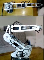
Axis robot 6-axis robotic arm
...ing parts drawings, standard parts purchased parts list, can be produced directly according to the drawings, welcome to download!
3ddd
free
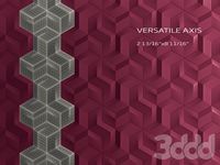
Versatile Axis
...ddd
nexus , плитка
http://bvtileandstone.com/ceramic-porcelain/versatile-axis/
3d_export
$19
robot 2 axis
...robot 2 axis
3dexport
robot 2 axis
turbosquid
$40
Axis R5F
... available on turbo squid, the world's leading provider of digital 3d models for visualization, films, television, and games.
turbosquid
$40
Axis S5F
... available on turbo squid, the world's leading provider of digital 3d models for visualization, films, television, and games.
turbosquid
$30
Axis Athlon
... available on turbo squid, the world's leading provider of digital 3d models for visualization, films, television, and games.
turbosquid
$10
Linear Axis
... available on turbo squid, the world's leading provider of digital 3d models for visualization, films, television, and games.
3d_export
$15

drawing axis
...drawing axis
3dexport
simple rendering of the scene file
3ddd
$1
versatile axis ARC
...versatile axis arc
3ddd
versatile , плитка
versatile axis arc red dot design award
Z
3d_export
$5
nissan z
...nissan z
3dexport
nissan z
3ddd
$1

Vase Z
...vase z
3ddd
vase z
3ddd
$1
полотенцесушить Z
...полотенцесушить z
3ddd
полотенцесушитель
полотенцесушить z
design_connected
free

Z-Chair
...z-chair
designconnected
free 3d model of z-chair designed by karman, aleksei.
design_connected
$11

Z Lamp
...z lamp
designconnected
phillips z lamp computer generated 3d model. designed by kalff, louis.
3d_export
$5
Dragon balls z
...dragon balls z
3dexport
dragon ball z
turbosquid
$20

Fighter Z
...
turbosquid
royalty free 3d model fighter z for download as on turbosquid: 3d models for games, architecture, videos. (1292563)
turbosquid
$9

Pen Z
...pen z
turbosquid
free 3d model pen z for download as obj on turbosquid: 3d models for games, architecture, videos. (1686775)
turbosquid
free
z chair
...z chair
turbosquid
free 3d model z chair for download as max on turbosquid: 3d models for games, architecture, videos. (1410230)
turbosquid
$5

Letter Z
...urbosquid
royalty free 3d model letter z for download as max on turbosquid: 3d models for games, architecture, videos. (1408540)
Way
3ddd
$1

Backhausen Fabric WAY
...x 2014, 2013, 2011,
obj
__________________________________________http://www.backhausen.com/en/products/fabric-catalog/
design_connected
$16

Way Turqoise
...way turqoise
designconnected
way turqoise computer generated 3d model. designed by gemvall, karin.
turbosquid
$9

Gerard Way
...
royalty free 3d model gerard way for download as max and fbx on turbosquid: 3d models for games, architecture, videos. (1682114)
3ddd
$1

Formerin - MY WAY
... my way , угловой
диван formerin - my way, в размере, с текстурами.
turbosquid
$7

End Way
...ty free 3d model end way for download as ma, ma, fbx, and obj on turbosquid: 3d models for games, architecture, videos. (1688865)
turbosquid
$15

American way
... available on turbo squid, the world's leading provider of digital 3d models for visualization, films, television, and games.
turbosquid
$1
sub way
... available on turbo squid, the world's leading provider of digital 3d models for visualization, films, television, and games.
3ddd
$1

Pregno / WAY OF LIFE
...pregno / way of life
3ddd
гардероб , pregno
гардероб pregno way of life
design_connected
$16

Team - 4 ways
...team - 4 ways
designconnected
arper team - 4 ways computer generated 3d model. designed by lievore, alberto.
design_connected
$11

Wai Highboy Highboard
...wai highboy highboard
designconnected
bonaldo wai highboy highboard computer generated 3d model. designed by mazzer, mario.