Thingiverse

Yagi Antenna Fixtures
by Thingiverse
Last crawled date: 4 years, 3 months ago
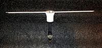
To build a yagi antenna, you need a dipole as the driven element, a reflector and one or more directors. I've created a holder for both the dipole driven element and the reflector/director that fit on a 3/4" non-conductive tube (21.5mm).
The dipole holder is made for 1/8" material with a separation between sides of the dipole of 2mm. A cavity is provided to accommodate solder joints from the coax (RG6) connection. The top is held on with 1 inch 6-32 screws. I chose to tap the dipole holder body for these threads and it ended up being quite strong. Silicone sealant is used to fill the rest of the internal void (coax connection) as well as the surface between the top and dipole holder body. I also filled the screw holes and antenna grooves with sealant to avoid as much moisture contamination as possible.
The reflector/director holder is a simple 1/8" through hole where the required length of material is held at its center.
Both dipole and R/D holders have a countersunk hole in the bottom intended to anchor the unit to the correct position on the antenna shaft.
The driven element is two sections of 1/8" brass, and the reflector/director are 1/8" aluminum (obtained at a welding supply store).
I built this antenna for a 390 MHz, but I've also done one in the same fashion at 435MHz (UHF HAM band). I highly recomment YagiCad by VK3DIP as it was incredibly useful to determine a starting point and then to tune it exactly. I highly recommend tuning with a Vector Network Analyser.
Using these the antenna came out to 52 ohm impedance, -5 ohms reactance, with a SWR of 1.13. Gain is simulated at 7.5dBi, but I've not verified it in the field yet.
Similar models
thingiverse
free

WiFi Yagi Supports by Technic2025
...please see my video for more details, spacing of the elements, and the design process!https://www.youtube.com/watch?v=mhgvs2ihnly
grabcad
free

Paperclip 5.6 GHz Folded Dipole with Reflector
...sign starting with this small paperclip folded dipole with matching reflector. both are mounted to 75 ohm 0.047" rigid coax.
grabcad
free

Paperclip 5.8 GHz Folded Dipole with Reflector
...sign starting with this small paperclip folded dipole with matching reflector. both are mounted to 75 ohm 0.047" rigid coax.
thingiverse
free

Retractable yagi antenna parts by Balua
....com/files/orig/f8h/zm28/h8xm1w8r/f8hzm28h8xm1w8r.jpg
it was also tested and verified. check instructions for more information.
thingiverse
free

Yagi-Uda antenna director holder with grip by SQ9MDD
...yagi-uda antenna director holder with grip by sq9mdd
thingiverse
yagi-uda antenna director holder with grip
thingiverse
free

Biquad Yagi Antenna - 2.4 GHz by ReallyBigTeeth
...e antenna to my usb wifi adaptor.
have a look at the video that inspired this design here: biquad yagi 2 4ghz and 5 8ghz upgrade!
thingiverse
free

Yagi Antenna element mounting tab by resago
... the center.
for "insulated" use 4 screws, on the sides.
full mount already has places for set screws, fully insulated.
thingiverse
free

Yagi antenna element mount for 2020 extrusion boom by RAThomas
...made this design for prototyping antennae. i do not expect it to be weatherproof for outdoor or permanent antenna installations.
thingiverse
free
Coax Dipole Antenna Enclosure by ka9etc
...provides an alternative to a pvc pipe enclosure or similar when installing a coax dipole outdoors. the structure keeps...
thingiverse
free

Yagi 2.4Ghz - 3mm elements by jfaerber
...elements:
59,7 mm - reflector
50,2mm - director 1
49,5mm - director 2
48,7mm - director 3
48,1mm - director 4
47,4mm - director 5
Yagi
turbosquid
$50

yagi
... available on turbo squid, the world's leading provider of digital 3d models for visualization, films, television, and games.
3d_export
$12

TV Aerial 1 3D Model
...uhf vhf band outdoor radio mast log periodic yagi-uda yagi array telecommunication digital tv aerial 1 3d model firdz3d...
3d_export
$10

Antenna 3D Model
...parabolic parabolle dish radio dishes telecom reception air wave yagi zx shortwave antenna 3d model mkms 35034...
thingiverse
free

Text by yagi
...text by yagi
thingiverse
just text
thingiverse
free

Yagi Support by GesehenFPV
...gesehenfpv
thingiverse
this is a simple yagi antenna support.
gopro standard connectors to connect with the main tripod support.
thingiverse
free

YAGI 15mm fi6 by norbert740
...yagi 15mm fi6 by norbert740
thingiverse
yagi boom elements mount 15 mm and fi6
thingiverse
free

Yagi Tripod mount
... quick tripod adapter for my yagi, might update it later to house a nut for the screw to go in. but works for a quick fix for now
thingiverse
free

yagi antenna by lellelel
...ng one of the many online calculators. this one is designed to use with the smaller diameter brazing rods, 2.3-2.5mm in thickness
thingiverse
free

Yagi Element Crib by gilifon
...yagi element crib by gilifon
thingiverse
a crib for 11 mm diameter yagi antenna elements.
the bottom surface is 25x20 mm.
thingiverse
free

Yagi Hanger by dlsspy
... hanging from a nail with a millitie and rubber band. decided to make something real quick to store it more easily and securely.
Antenna
archibase_planet
free
Antenna
...chibase planet
antenna aerial television antenna
antenna kathrein n090913 - 3d model (*.gsm+*.3ds) for exterior 3d visualization.
archibase_planet
free
Antenna
...antenna
archibase planet
satellite antenna
antenna 1 - 3d model (*.gsm+*.3ds) for exterior 3d visualization.
archibase_planet
free
Antenna
...antenna
archibase planet
equipment satellite antenna
antenna 2 - 3d model (*.gsm+*.3ds) for exterior 3d visualization.
archibase_planet
free
Antenna
...ntenna
archibase planet
satellite antenna equipment dish aerial
antenna 3 - 3d model (*.gsm+*.3ds) for exterior 3d visualization.
archibase_planet
free
Antenna
...antenna
archibase planet
satellite antenna dish dish aerial
antenna 4 - 3d model (*.gsm+*.3ds) for exterior 3d visualization.
archibase_planet
free
Antenna
...e planet
antenna dish dish aerial
antenna c-band satellite s180-g n210612 - 3d model (*.gsm+*.3ds) for exterior 3d visualization.
3d_export
$5
car antenna
...car antenna
3dexport
car antenna, antenna, car gadgets
turbosquid
$1

antenna
...rbosquid
royalty free 3d model antenna for download as blend on turbosquid: 3d models for games, architecture, videos. (1655786)
3d_export
free

Station with antenna
...station with antenna
3dexport
station with antenna
turbosquid
$5
Antenna
...id
royalty free 3d model antenna for download as max and fbx on turbosquid: 3d models for games, architecture, videos. (1381532)
Fixtures
turbosquid
$5

Fixture
...turbosquid
royalty free 3d model fixture for download as max on turbosquid: 3d models for games, architecture, videos. (1160462)
turbosquid
$39

FIXTURE
...id
royalty free 3d model fixture for download as ige and obj on turbosquid: 3d models for games, architecture, videos. (1332983)
turbosquid
$2

Fixture
... available on turbo squid, the world's leading provider of digital 3d models for visualization, films, television, and games.
turbosquid
$1

fixture
... available on turbo squid, the world's leading provider of digital 3d models for visualization, films, television, and games.
turbosquid
$1

fixture
... available on turbo squid, the world's leading provider of digital 3d models for visualization, films, television, and games.
3d_export
$10

ROBOT FIXTURE
...fixture
3dexport
it is a robot fixture. it is used to pick the insert from the table and place that insert into the mold cavity.
turbosquid
free

lighting fixtures
...odel lighting fixtures for download as 3ds, max, obj, and fbx on turbosquid: 3d models for games, architecture, videos. (1428616)
3d_ocean
$2

Light Fixture 02
...light fixture 02 3docean electric electronic enviroment fixture fixtures for game game ready light lights low poly ready...
turbosquid
$29

bathroom fixtures
...odel bathroom fixtures for download as 3ds, max, obj, and c4d on turbosquid: 3d models for games, architecture, videos. (1180328)
turbosquid
$20

Wall Fixture
... 3d model wall fixture for download as 3ds, obj, c4d, and fbx on turbosquid: 3d models for games, architecture, videos. (1270353)