Thingiverse
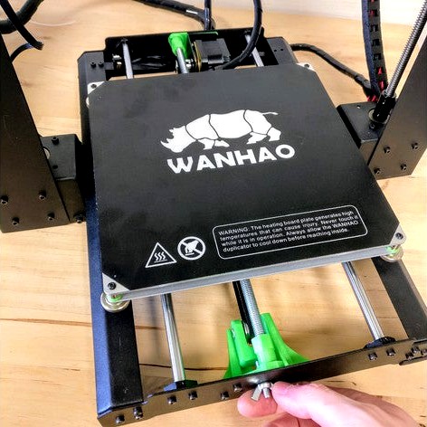
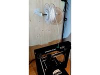
Y-axis Brace and Tensioner for Wanha Di3 by printingotb
by Thingiverse
Last crawled date: 3 years ago
What
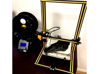
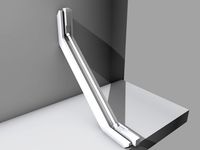
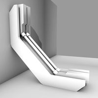
A Y-axis brace and belt tensioner, with consideration taken for the Y motor staying perpendicular to the belt even when using stepper dampers (I recommend dampers to lower noise. I have tested and not been able to detect any effect on print quality, neither good nor bad).
Why
For easy adjustment of the Y axis belt-tension.
For being able to tighten the Y axis without flexing the frame and throwing the Y motor out of alignment. This is especially helpful when using stepper dampers.
I use a guitar-tuning app to tune the tension of my belts to 100Hz. Please note that I do not know what the perfect tension is or how accurate the app is.
Options
You can use the tensioner without the bracing rod if you drill a hole in the frame for the third M3 screw for the YTensionerBody. This screw is not necessary with the bracing rod.
You can use the stock idler but I provide a second version of the idler holder made for two flanged bearings instead. The flanged bearings require two M5 washers.
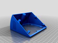
The RearBracket comes in two versions:
With a small 1° angle to compensate for the motor bracket bending slightly.
With a larger 3° angle to also compensate for a stepper damper being flexible.
Hardware needed
List of US SAE hardware needed can be found in this awesome looking make by Fatman66 https://www.thingiverse.com/make:529646
Metric hardware needed:
(If you want to use the tensioner without the brace, you will need an extra M3 nut.)
Preferably one 3mm drill and one 5,5 - 6mm drill
Two M3x5mm screws (re-use from old idler bracket)
Two M3 nuts
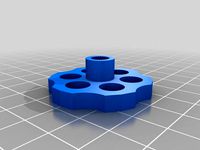
One M5 nut, preferably winged, OR print the "Knob.stl"
One M5 nut
One M5 locknut for stock idler or One standard M5 nut for flanged bearings.
One M5x25 screw with hexagonal head (longer will work)
One M5x30 screw with hexagonal head (longer will work)
Either
One M8 threaded rod, 377mm long (print two "M8CenteringNuts")
Or
One 5/16-18" threaded rod, 10,9" long (print two "5-16-18 Nuts")**Optionally**
Two flanged bearings with inner Ø5mm, outer Ø16mm, thickness 5mm (flange Ø18).
And two M5 washers.
Print recommendations
5 walls
0,16 layer height
No supports needed on any parts, including the Knob.
Installation
See pictures
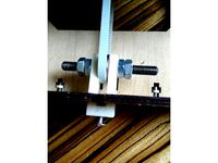
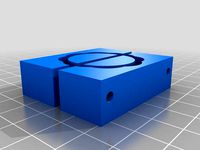
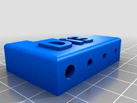
-Mount the DrillHelper and make sure it is level with the top of the frame
While holding it in place, drill a 3mm hole and then a 6mm hole. To get a cleaner exit, use a 5.5mm drill before the 6mm hole.
De-burr, use a file if necessary.
-Insert the M3 nuts in the YTensionerBody, (glue them if you like).
Install it on the frame, it should be level with the upper edge of the frame but 0,5-1mm below.
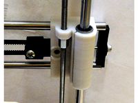
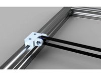
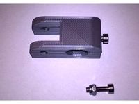
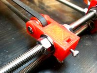
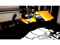
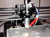
-Assemble the BearingHolder, start with inserting the 30mm hexagonal screw in the bottom and put the belt around the bearing(s). Insert the 25mm hexagonal screw through the Holder and bearing(s). For the stock idler it looks like this: Holder-idler-holder-Locknut. For the dual flanged bearings it looks like this: Holder-washer-flanged_bearingx2-washer-holder-nut.
Insert the assembled BearingHolder in the YTensionerBody with the 30mm screw going through the frame and into a (winged) nut. The BearingHolder should have a distance of roughly 13mm (0,5") between itself and the YTensionerBody to allow maximum space for tightening. Don't go further away since it will not be guided well.
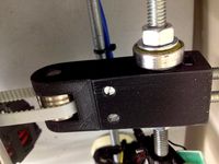
-Remove the the screws holding the motor mount and put a RearBracket between the frame and mount. If you use a Stepper damper, choose the 3° version, otherwise choose the 1° version. If you use the 3° rear bracket, you can't use all three stock screws but it will still work with only two. Alternatively, use a longer screw and perhaps some washers to prevent it from touching the motor.
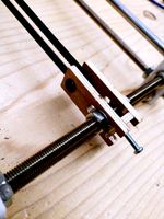
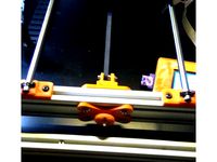
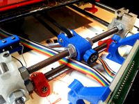
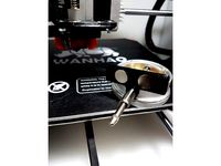
-Screw on a M8CenteringNut on each end of the threaded rod and insert in it's sockets.
Screw the nuts towards the frame on both ends until it is locked in place.
Make sure the belt runs as it should and shorten the belt preliminary. Use only one zip-tie for now.
-Start to tighten the belt using the winged nut and watch the frame's front and rear to see if it flexes. Do not over-tighten.
If necessary, adjust the M8CenteringNuts until the front and rear is decently straight.
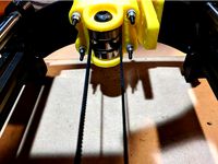
Carefully check that no parts is touching the bed carriage while moving the bed by hand (slowly to not generate back-current with the motor).
-Check that the motor shaft is decently perpendicular to the belt. To some degree, you can adjust the M8CenteringNuts to intentionally flex the front and rear of the frame to adjust the angle a bit.
-When everything is fine, put on a second zip-tie and cut off the excess belt. Also adjust the screws holding the belt so that the belt is in line with the motor and idler.
-Print a couple of things and recheck the tension.
Debugging
Q: I get a ticking noise from the belt when the bed travels near one end of the printer.
A: It is likely that you need to adjust on of the screws that holds the belt under the bed, or the belts position on it. This will prevent the belt from trying to climb the bearing edge/flange.
A Y-axis brace and belt tensioner, with consideration taken for the Y motor staying perpendicular to the belt even when using stepper dampers (I recommend dampers to lower noise. I have tested and not been able to detect any effect on print quality, neither good nor bad).
Why
For easy adjustment of the Y axis belt-tension.
For being able to tighten the Y axis without flexing the frame and throwing the Y motor out of alignment. This is especially helpful when using stepper dampers.
I use a guitar-tuning app to tune the tension of my belts to 100Hz. Please note that I do not know what the perfect tension is or how accurate the app is.
Options
You can use the tensioner without the bracing rod if you drill a hole in the frame for the third M3 screw for the YTensionerBody. This screw is not necessary with the bracing rod.
You can use the stock idler but I provide a second version of the idler holder made for two flanged bearings instead. The flanged bearings require two M5 washers.
The RearBracket comes in two versions:
With a small 1° angle to compensate for the motor bracket bending slightly.
With a larger 3° angle to also compensate for a stepper damper being flexible.
Hardware needed
List of US SAE hardware needed can be found in this awesome looking make by Fatman66 https://www.thingiverse.com/make:529646
Metric hardware needed:
(If you want to use the tensioner without the brace, you will need an extra M3 nut.)
Preferably one 3mm drill and one 5,5 - 6mm drill
Two M3x5mm screws (re-use from old idler bracket)
Two M3 nuts
One M5 nut, preferably winged, OR print the "Knob.stl"
One M5 nut
One M5 locknut for stock idler or One standard M5 nut for flanged bearings.
One M5x25 screw with hexagonal head (longer will work)
One M5x30 screw with hexagonal head (longer will work)
Either
One M8 threaded rod, 377mm long (print two "M8CenteringNuts")
Or
One 5/16-18" threaded rod, 10,9" long (print two "5-16-18 Nuts")**Optionally**
Two flanged bearings with inner Ø5mm, outer Ø16mm, thickness 5mm (flange Ø18).
And two M5 washers.
Print recommendations
5 walls
0,16 layer height
No supports needed on any parts, including the Knob.
Installation
See pictures
-Mount the DrillHelper and make sure it is level with the top of the frame
While holding it in place, drill a 3mm hole and then a 6mm hole. To get a cleaner exit, use a 5.5mm drill before the 6mm hole.
De-burr, use a file if necessary.
-Insert the M3 nuts in the YTensionerBody, (glue them if you like).
Install it on the frame, it should be level with the upper edge of the frame but 0,5-1mm below.
-Assemble the BearingHolder, start with inserting the 30mm hexagonal screw in the bottom and put the belt around the bearing(s). Insert the 25mm hexagonal screw through the Holder and bearing(s). For the stock idler it looks like this: Holder-idler-holder-Locknut. For the dual flanged bearings it looks like this: Holder-washer-flanged_bearingx2-washer-holder-nut.
Insert the assembled BearingHolder in the YTensionerBody with the 30mm screw going through the frame and into a (winged) nut. The BearingHolder should have a distance of roughly 13mm (0,5") between itself and the YTensionerBody to allow maximum space for tightening. Don't go further away since it will not be guided well.
-Remove the the screws holding the motor mount and put a RearBracket between the frame and mount. If you use a Stepper damper, choose the 3° version, otherwise choose the 1° version. If you use the 3° rear bracket, you can't use all three stock screws but it will still work with only two. Alternatively, use a longer screw and perhaps some washers to prevent it from touching the motor.
-Screw on a M8CenteringNut on each end of the threaded rod and insert in it's sockets.
Screw the nuts towards the frame on both ends until it is locked in place.
Make sure the belt runs as it should and shorten the belt preliminary. Use only one zip-tie for now.
-Start to tighten the belt using the winged nut and watch the frame's front and rear to see if it flexes. Do not over-tighten.
If necessary, adjust the M8CenteringNuts until the front and rear is decently straight.
Carefully check that no parts is touching the bed carriage while moving the bed by hand (slowly to not generate back-current with the motor).
-Check that the motor shaft is decently perpendicular to the belt. To some degree, you can adjust the M8CenteringNuts to intentionally flex the front and rear of the frame to adjust the angle a bit.
-When everything is fine, put on a second zip-tie and cut off the excess belt. Also adjust the screws holding the belt so that the belt is in line with the motor and idler.
-Print a couple of things and recheck the tension.
Debugging
Q: I get a ticking noise from the belt when the bed travels near one end of the printer.
A: It is likely that you need to adjust on of the screws that holds the belt under the bed, or the belts position on it. This will prevent the belt from trying to climb the bearing edge/flange.
Similar models
thingiverse
free
Y-Axis tensioner/Idler by lslewis901
... screw and two m4 nuts for tension adjuster.
the design is made to allow placement of part after printer frame already assembled.
thingiverse
free
Belt Tensioner - Idle Pulley for Prusa Mendel I2 by Chris918
... old 608 bearing idler on the frame's threaded rod. it is acting as a washer on one side between the nut and the tensioner ;)
thingiverse
free
Sintron i3 X Axis Tension kit by JWag
...der washer into the two 3mm holes on the bracket. this should increase the strength of the bracket and keep it from delaminating.
thingiverse
free
Graber I3 Y-Belt Tensioner by keinervonuns
...imple y-belt tensioner for graber i3.
parts list
608 skate bearing
m8 threaded rod or screw + nuts
m5 screw to adjust the tension
thingiverse
free
FolgerTech 2020 Y Axis Idler Bearing Holder by JWag
...er over the bolt and thread on the nylock
attach the holder to the 2020 frame with m5 bolts and t-nuts.
tension your y-axis belt.
thingiverse
free
Y belt tensioner for 2020 and 2040 aluminum extrusion by FFranzmann
...f prusa and haribo mod designs
you need to drill a hole for the m4 in your extrusion
added a version for 2020 although untested.
thingiverse
free
Extended Externally Accessible Y Belt Idler with Tensioner by Naonak
...oom to slide the belt up and down, giving you more options for how to mount your motor or make other modifications to the y-axis!
thingiverse
free
Prusa_I3_MK2_Y_Belt_Idler_Tensioner by Andison
... and washers.
the idler is designed in a way that it does not impact heat bed movement or minimize printing area respectively.
thingiverse
free
Y axis idler tensioner by tonymtsai
... section in the scad file.
uses the m5 nut and bolt and two 625 bearings
tightening is done via a m3 nut and bolt at the back
thingiverse
free
prusa i3 Y idler with belt tightener. by liusega
...ith belt tightener. by liusega
thingiverse
prusa i3 y idler with belt tightener
m5x20 screw x1
m5 nut
m3x15 screw x1
m3 nut x1
Wanha
3dwarehouse
free

Wanha pirtti
...wanha pirtti
3dwarehouse
wanha pirtti, tyrävaara old house, finland
3dwarehouse
free

Wanha Villatehdas
...wanha villatehdas
3dwarehouse
old woolfactory
3dwarehouse
free

The Church of the Holy Cross (Rauma)
...#church #cross #fransiscan #holy #kirkko #monastery #old #rauma #vanha #wanha ...
Printingotb
thingiverse
free
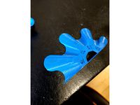
DecapiCat by printingotb
...support under the tongue and the lowest part of he head.
attached my support settings but they are by no means the best settings.
thingiverse
free
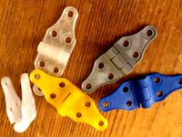
Hinges by printingotb
...tertight and suitable for 3d-printing.
i have printed these in every material i have tried. pla, abs, petg, nylon all work well.
thingiverse
free
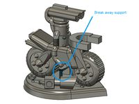
Robo Rally Twitch upgrade by printingotb
...ree supports + a modelled custom break away support under the middle.
a total 1.5 workdays to design, print and paint.
100% happy
thingiverse
free
Curve Overhang test *halved* by printingotb
...all lines works better than more but only if you allow the bottom skin on top of the walls, see picture from cura (yellow areas).
thingiverse
free
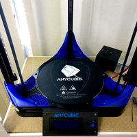
Anycubic kossel L+ Corner Supports and Bed holder by printingotb
...ee pictures for instructions.
the top corners can be used everywhere if you only want the corner supports and not the bed holder.
thingiverse
free
Z-Brace 0.5 by printingotb
...ble "helper" to get the holes right as well as easy to follow instructions.
https://www.youtube.com/watch?v=aglek3ychea
thingiverse
free
Spool core with sides for Eco refill by printingotb
...es.
cut-out for layer seam on inner diameter.
lots of holes for attaching the filament end
designated place for material sticker.
thingiverse
free
Stepper Smoother Box by printingotb
...ave one:https://www.thingiverse.com/thing:1997411
performance
see second picture, the issue was mild on my printer to begin with.
thingiverse
free
Simple topmounted spoolholder for enclosure by printingotb
...ss.
oh, and no need to mount it so close to the edge of your enclosure, i had a leaning ceiling just above my printer before :-p
thingiverse
free
CR10 2.3kg Spool Holder for controlbox by printingotb
...realized that there is not enough space for them lol.
feel free to remix this in any way you want :)
https://youtu.be/sw5s5zl6jey
Di3
thingiverse
free
Wanhao Di3 v2 Light / Wanhao Di3 v2 Beleuchtung by JMDesigns
...wanhao di3 v2 light / wanhao di3 v2 beleuchtung by jmdesigns
thingiverse
wanhao di3 v2 light / wanhao di3 v2 beleuchtung
thingiverse
free
Wanhao Di3 MagFix System by JMDesigns
...wanhao di3 magfix system by jmdesigns
thingiverse
wanhao di3 magfix system
thingiverse
free
Wanhao Di3 Silicone Softgrip by JMDesigns
...wanhao di3 silicone softgrip by jmdesigns
thingiverse
wanhao di3 silicone softgrip
thingiverse
free
Di3 rotary dial by 3Dplanner
...hingiverse
original model of jo3ri http://www.thingiverse.com/thing:33286 , adjusted for the di3.
layer 0.2
shell 2
fill 50%
pla
thingiverse
free
Di3 LCD Angler ( With Air Vents ) by diamonddrake
...3 lcd angler ( with air vents ) by diamonddrake
thingiverse
this is a remix of rtideas di3 lcd angler, i simply added air vents.
thingiverse
free
Di3 Hex Wrench Holder by BliNDF123
...de a hex wrench holder for the ones that come with the di3, stuck it to the side frame of my printer with some double sided tape.
thingiverse
free
E3D v6 mount for Wanhao Di3 by slimc
...w design http://www.thingiverse.com/thing:1657971
set of components that allow the e3d v6 hotend to be mounted on the wanhao di3.
thingiverse
free

Wanhao Di3 V2.1 Knob Grip by Hyperlinks
...
thingiverse
this is a remix for the di3 v2.1. it did not fit properly on my printer (too tall), so i scaled it down minus 7 mm.
thingiverse
free
Wanhao Di3+ filament cleaner by Alpin3D
...wanhao di3+ filament cleaner by alpin3d
thingiverse
v1.1
filament cleaner / sponge
v1.2
better filament control
thingiverse
free
Di3 Nozzle LED Mount by sprfly
...e cooler. uses a 3 led section of self adhesive strip leds. i tapped into the always on hotend fan to provide the 12v to my leds.
Brace
archive3d
free
Bracing 3D Model
...
holder bracing strengthening
bracing 4 - 3d model (*.gsm+*.3ds) for interior 3d visualization.
archive3d
free
Bracing 3D Model
...
bracing strengthening holder
bracing 2 - 3d model (*.gsm+*.3ds) for interior 3d visualization.
turbosquid
$5

brace PARIS
...osquid
royalty free 3d model brace paris for download as max on turbosquid: 3d models for games, architecture, videos. (1284415)
archive3d
free
Bracing 3D Model
...older fastening strengthening
bracing 1 - 3d model (*.gsm+*.3ds) for interior 3d visualization.
archive3d
free
Bracing 3D Model
...older fastening strengthening
bracing 3 - 3d model (*.gsm+*.3ds) for interior 3d visualization.
turbosquid
$20
Corner Brace Bracket
...oyalty free 3d model corner brace bracket for download as stl on turbosquid: 3d models for games, architecture, videos. (1322777)
turbosquid
$10

Craftsman Handtools - Brace
... available on turbo squid, the world's leading provider of digital 3d models for visualization, films, television, and games.
turbosquid
$2
Degree Brace 4
...el degree brace 4 for download as 3ds, max, obj, c4d, and fbx on turbosquid: 3d models for games, architecture, videos. (1205705)
turbosquid
$1
Degree Brace 3
...el degree brace 3 for download as 3ds, max, obj, c4d, and fbx on turbosquid: 3d models for games, architecture, videos. (1205719)
turbosquid
$1
Degree Brace 2
...el degree brace 2 for download as 3ds, max, obj, c4d, and fbx on turbosquid: 3d models for games, architecture, videos. (1205714)
Tensioner
3d_export
$5
adjustable tension lock
...adjustable tension lock
3dexport
adjustable tension lock
turbosquid
$5

tension ring
...oyalty free 3d model tension ring for download as fbx and stl on turbosquid: 3d models for games, architecture, videos. (1553452)
turbosquid
$3

Tension Chair
...free 3d model tension chair for download as obj, c4d, and fbx on turbosquid: 3d models for games, architecture, videos. (1251503)
3d_export
$5
transformador de tension
...transformador de tension
3dexport
transformador de tension entrada 460vac salida 220vac marca audax
turbosquid
$20

Motorbike Chain Tensioner
...y free 3d model motorbike chain tensioner for download as stl on turbosquid: 3d models for games, architecture, videos. (1428322)
turbosquid
$25
TENSION-WOOD-CHAIR
... available on turbo squid, the world's leading provider of digital 3d models for visualization, films, television, and games.
turbosquid
$25

tension-bentwood-chair
... available on turbo squid, the world's leading provider of digital 3d models for visualization, films, television, and games.
turbosquid
$19
Tension engagement ring
...n engagement ring for download as obj, fbx, 3dm, dwg, and stl on turbosquid: 3d models for games, architecture, videos. (1491631)
3d_export
$10

Ruby Tension set Ring 3D Model
...ruby tension set ring 3d model
3dexport
tension set ruby ring in 18k
ruby tension set ring 3d model rehansheikh 25254 3dexport
turbosquid
$20
Superficial Tension Exp. Image.max
... available on turbo squid, the world's leading provider of digital 3d models for visualization, films, television, and games.
Axis
3ddd
$1

Мария Axis
...
3ddd
кухня , классическая , axis
модель кухни.
3d_export
$22
Axis robot 6-axis robotic arm
...ing parts drawings, standard parts purchased parts list, can be produced directly according to the drawings, welcome to download!
3ddd
free

Versatile Axis
...ddd
nexus , плитка
http://bvtileandstone.com/ceramic-porcelain/versatile-axis/
3d_export
$19
robot 2 axis
...robot 2 axis
3dexport
robot 2 axis
turbosquid
$40
Axis R5F
... available on turbo squid, the world's leading provider of digital 3d models for visualization, films, television, and games.
turbosquid
$40
Axis S5F
... available on turbo squid, the world's leading provider of digital 3d models for visualization, films, television, and games.
turbosquid
$30

Axis Athlon
... available on turbo squid, the world's leading provider of digital 3d models for visualization, films, television, and games.
turbosquid
$10

Linear Axis
... available on turbo squid, the world's leading provider of digital 3d models for visualization, films, television, and games.
3d_export
$15

drawing axis
...drawing axis
3dexport
simple rendering of the scene file
3ddd
$1

versatile axis ARC
...versatile axis arc
3ddd
versatile , плитка
versatile axis arc red dot design award
Y
turbosquid
$1

Tetera y Galletas y Caf
... available on turbo squid, the world's leading provider of digital 3d models for visualization, films, television, and games.
3ddd
$1

Смеситель Y-CON
...смеситель y-con
3ddd
смеситель , y-con
смеситель y-con
3ddd
$1
Y-Chair
...y-chair
3ddd
tom dixon
y-chair designed by tom dixon,
3ds max + obj, corona
3ddd
$1
Y Chair compilation
....net/products/us/y-chair-sled-base
y chair swivel basehttp://www.tomdixon.net/products/us/y-chair-swivel-base
turbosquid
$190
Y-8
...y-8
turbosquid
royalty free 3d model y-8 for download as max on turbosquid: 3d models for games, architecture, videos. (1658891)
turbosquid
$7
Bench Y
...turbosquid
royalty free 3d model bench y for download as obj on turbosquid: 3d models for games, architecture, videos. (1488746)
turbosquid
$15

bonePile Y
...oyalty free 3d model bonepile y for download as blend and obj on turbosquid: 3d models for games, architecture, videos. (1546374)
turbosquid
$7

Y for Yarn
...d
royalty free 3d model y for yarn model for download as max on turbosquid: 3d models for games, architecture, videos. (1699732)
turbosquid
$2
FONT Y
...quid
royalty free 3d model font y for download as ma and obj on turbosquid: 3d models for games, architecture, videos. (1549457)
3ddd
$1

WOOD-y
...wood-y
3ddd
wooden guy