Thingiverse
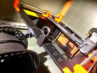
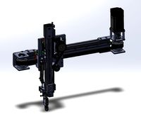
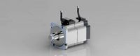
X Axis motor mount for Anet A8 or Prusa i3 by Randino
by Thingiverse
Last crawled date: 3 years ago
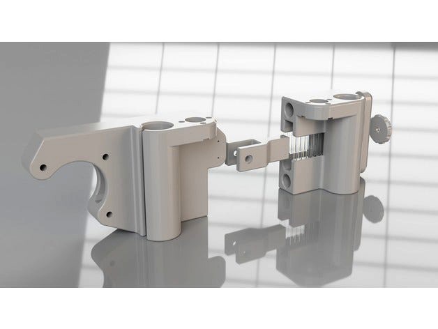
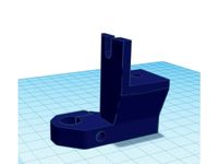
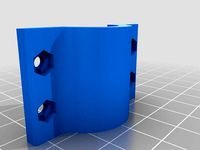
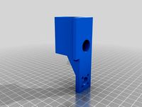
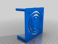
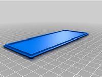
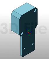
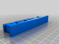
This is a ground-up redesign of "thing" 1428253 using Fusion 360. I used a slight teardrop shape at the top (when printing) of the horizontal holes to avoid sagging on the bridging at the top of the holes. I also used 1mm fillets at all of the corners, so the printer would not have to slowdown or overrun tight corners. These changes allowed the tolerance to be a lot tighter than the original design. The holes are 8.18mm (originally 8.6), although I did have to use some light bearing oil to slide the rods in. Linear bearing holes are slightly tighter too (15.08 vs. 15.2). There are other cosmetic and functional changes.
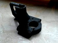
After you print, you probably want to sand the bottom (that will be the top when flipped). I used 600 sandpaper. This is in case there was any curling/warping off the bed during printing. You want those huge nuts for the z-axis screws to be as level as possible.
All of the screws and nuts are 3mm in my design. I used a left over 45mm screw from my printer for the pulley/thumbscrew. I also used 3mm locknuts, although plain nuts should work too.
Printing
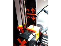
Depending on your printer, use either the standard Left/Right files which have 45mm spacing between rod axes, or the 44mm/46mm variants of those files.
Do not use supports
Enable Avoid crossing perimeters or equivalent so you don't have any garbage to clean up where the rods or linear bearing go.
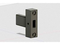
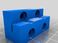
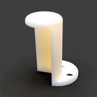
The test_fit.stl file can be used to check how tight the fit is with your printer and slicer settings. The hole in this file is the normal (8.18mm) size.
Assembly
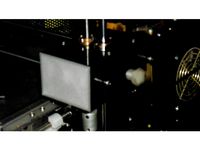
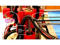
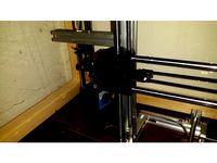
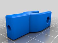
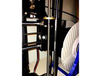
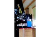
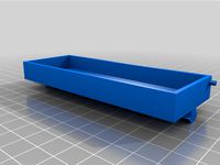
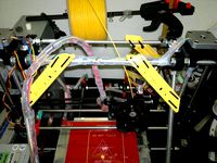
After inserting the horizontal rods, rotate both of them in place (simultaneously) to relieve any stress on your Z-axis rods. Then tighten the two outer screws on the "tensioner" just enough that it begins to separate. This ensures that the horizontal rods are providing the belt tension (and not your Z-axis).
Updates:
I added a second version of the right side that is slightly looser than the left side, in case you don't want to struggle to slide the rods across. It is 8.32mm instead of 8.18mm.
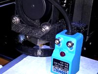
Made the screw holes for the endstop switch a little bigger
Added a small shape for test-fitting just the hole
Added variations with 44mm and 46mm rod spacing (vs. standard 45mm)
After you print, you probably want to sand the bottom (that will be the top when flipped). I used 600 sandpaper. This is in case there was any curling/warping off the bed during printing. You want those huge nuts for the z-axis screws to be as level as possible.
All of the screws and nuts are 3mm in my design. I used a left over 45mm screw from my printer for the pulley/thumbscrew. I also used 3mm locknuts, although plain nuts should work too.
Printing
Depending on your printer, use either the standard Left/Right files which have 45mm spacing between rod axes, or the 44mm/46mm variants of those files.
Do not use supports
Enable Avoid crossing perimeters or equivalent so you don't have any garbage to clean up where the rods or linear bearing go.
The test_fit.stl file can be used to check how tight the fit is with your printer and slicer settings. The hole in this file is the normal (8.18mm) size.
Assembly
After inserting the horizontal rods, rotate both of them in place (simultaneously) to relieve any stress on your Z-axis rods. Then tighten the two outer screws on the "tensioner" just enough that it begins to separate. This ensures that the horizontal rods are providing the belt tension (and not your Z-axis).
Updates:
I added a second version of the right side that is slightly looser than the left side, in case you don't want to struggle to slide the rods across. It is 8.32mm instead of 8.18mm.
Made the screw holes for the endstop switch a little bigger
Added a small shape for test-fitting just the hole
Added variations with 44mm and 46mm rod spacing (vs. standard 45mm)
Similar models
thingiverse
free
horizontal x axis x ends for flange nuts by karrack
...int for the z rods such as the mendelmax oder prism
built-in hole bridging needs to be removed after print
prints without support
thingiverse
free
Prusa i3 Mk2 X Axis Tensioner by filament_junkie
...20mm) to allow for belt tension adjustment.
it puts tension on the end of the x axis rods so not to bend the z axis smooth rods.
thingiverse
free

Improved Geeetech Aluminum Anti-Wobble Bracket by B-Cup
... a tower to place supports on, so do not forget to add supports in between!
it uses the original brass nuts for the z axis rods.
thingiverse
free
A6 X-Belt tensioner "V1-V2" adjustable pressure on Z-axis rods by DaveLado
...the x-axis rods from the z-axis rods by adjusting the screws.
after that, tight the belt of the x-axis after.
have a good print!!
thingiverse
free
Hictop Left Side X & Z Axis Lift Screw by chaoren
... that you can tie down the wire coming off of the x limit switch so it doesn't break.
i recommend 100% infill printed in abs.
thingiverse
free
Hictop Right Side X & Z Axis Lift Screw by chaoren
...ck nut.
you can get the springs here:https://www.amazon.com/gp/product/b015clfiyo/ref=oh_aui_detailpage_o09_s00?ie=utf8&psc=1
thingiverse
free
Z axis 12mm rod 3030 hypercube remix by dakarx
... frame and m3 screw for tension. i printed at 80% infill for added strength and rigidity. this is for my hypercube 500 project
thingiverse
free
X-axis Tensioner to avoid forces on Z-axis by SteevyT
... x3
3mm washer x1
3-5mm drill bit (and a tool to run it in)
the bearings, screw, and nut from the original set up on the printer.
thingiverse
free
Junior 1.0 linear bearing in the Z-right rod by sicicop
...ar bearing.
to hold the bearing is needed 4 m3x10mm screws and 4 nuts. also need 2 m3x8mm screws to attach in the x axis carriage
thingiverse
free
Monoprice Select Mini dual z motor adapters by mfink70
... and needs.
update: 2/17/18
added a mount that will use 6mm linear bearings for those that have a 6mm rod for their z stabilizer.
Randino
thingiverse
free
Toothed idler fork A8 I3 for Randinos mounts
...ngiverse that fit the bill, so i whipped this up in ds mechanical real quick. credit goes to randino as i based it on his design.
thingiverse
free
X-axis Belt Tension for STARTT (TronXY XY-100) by Bkult3
...mount for anet a8 or prusa i3" posted by randino see misc. notes for assembly...
3dwarehouse
free

Memorial Stadium
...stadium 3dwarehouse and old baseball stadium. 100% fictional. origianly randino#39;s old yankee stadium. #baseball #mlb #old_baseball_stadium #old_stadium...
A8
turbosquid
$47

Car A8
...
turbosquid
royalty free 3d model car a8 for download as max on turbosquid: 3d models for games, architecture, videos. (1196060)
turbosquid
$50

Audi A8
...yalty free 3d model audi a8 for download as 3dm, obj, and fbx on turbosquid: 3d models for games, architecture, videos. (1580187)
turbosquid
$15

Audi A8
...lty free 3d model audi a8 for download as obj, fbx, and blend on turbosquid: 3d models for games, architecture, videos. (1387519)
turbosquid
$500

Audi A8
... available on turbo squid, the world's leading provider of digital 3d models for visualization, films, television, and games.
3d_export
$5

Audi A8 3D Model
...audi a8 3d model
3dexport
audi a8 cars car
audi a8 3d model ma 20351 3dexport
3d_export
$5

Audi A8 3D Model
...audi a8 3d model
3dexport
3d model of audi a8
audi a8 3d model badyaka 12136 3dexport
3d_ocean
$89

Audi A8 2010
...usiness car car class class f f german german luxury luxury s s s8 s8 sedan sedan vehicle vehicle
new audi a8 2010 detaled model.
turbosquid
$39

A8 2018
...a8 2018 for download as 3ds, obj, wrl, c4d, fbx, dae, and stl on turbosquid: 3d models for games, architecture, videos. (1345349)
turbosquid
free

audi a8 l
...rbosquid
royalty free 3d model audi a8 l for download as obj on turbosquid: 3d models for games, architecture, videos. (1663016)
3d_ocean
$45

Audi A8 restyled
...our door vehicle was created in blender3d 2.62.realistic renderings were created with yafaray 0.1.2 realistic plugin.rendering...
Anet
thingiverse
free

Anet by derbodesign
...anet by derbodesign
thingiverse
logo anet
thingiverse
free
Anet e10 , Anet v1.0 by jonathan_943D
...anet e10 , anet v1.0 by jonathan_943d
thingiverse
soporte de ventilador de 80mm, para controladora anet v1.0
thingiverse
free
Anet A8 Anet AM8 Y belt holder
...anet a8 anet am8 y belt holder
thingiverse
anet a8 anet am8 y belt holder
thingiverse
free
Anet A8 Probe Bracket for anet sensor by chelrix
...anet a8 probe bracket for anet sensor by chelrix
thingiverse
anet a8 probe bracket for anet official sensor and marlin firmware
thingiverse
free

Anet logo by JUST3D_PRNTNG
...anet logo by just3d_prntng
thingiverse
anet logo
thingiverse
free
Fan nozzle for Anet A8 with original Anet levelsensor by peteruhlmann
...et levelsensor by peteruhlmann
thingiverse
here is an improved fan nozzle for the anet a8 with original level sensor from anet.
thingiverse
free
Anet Et4 Box
...anet et4 box
thingiverse
tool box for anet et4
thingiverse
free
Anet Logo by Superflex_Plastic_Fantastic
...anet logo by superflex_plastic_fantastic
thingiverse
anet logo to incorporate into designs.
thingiverse
free
Box for Anet ET4
...box for anet et4
thingiverse
this is a simple box for tool of anet et4
thingiverse
free

Anet V1.0 Board Kühlung (80mm Lüfter) / Anet A8 by MadCre8
...anet v1.0 board kühlung (80mm lüfter) / anet a8 by madcre8
thingiverse
anet v1.0 board kühlung (80mm lüfter) / anet a8
I3
3d_export
$10
suv i3
...suv i3
3dexport
suv i3 2013 series
3d_ocean
$89

BMW i3 2012
...y, in real units of measurement, qualitatively and maximally close to the original. model formats: - *.max (3ds max 2008 scanl...
cg_studio
$99

BMW i3 20143d model
...
cgstudio
.3ds .c4d .fbx .lwo .max .obj - bmw i3 2014 3d model, royalty free license available, instant download after purchase.
cg_studio
$99

BMW i3 20123d model
...tudio
.3ds .c4d .fbx .lwo .max .mb .obj - bmw i3 2012 3d model, royalty free license available, instant download after purchase.
cg_studio
$99

BMW i3 20143d model
...tudio
.3ds .c4d .fbx .lwo .max .mb .obj - bmw i3 2014 3d model, royalty free license available, instant download after purchase.
humster3d
$75

3D model of BMW i3 2014
...
buy a detailed 3d model of bmw i3 2014 in various file formats. all our 3d models were created maximally close to the original.
humster3d
$40

3D model of Kitchen Set I3
...uy a detailed 3d model of kitchen set i3 in various file formats. all our 3d models were created maximally close to the original.
3d_ocean
$30

Kitchen set i3
...ensils oven plates shelves sink table ware
kitchen set i3 include 3d models: cooker, oven, sink, cupboards, table, chair, plates.
3d_ocean
$89

BMW i3 2014
...y, in real units of measurement, qualitatively and maximally close to the original. model formats: - *.max (3ds max 2008 scanl...
cg_studio
$99

BMW i3 Concept 20113d model
...i3
.3ds .c4d .fbx .lwo .max .obj - bmw i3 concept 2011 3d model, royalty free license available, instant download after purchase.
Prusa
turbosquid
$2
Frame Filament Guide Clip-On for Prusa Mk3
...rame filament guide clip-on for prusa mk3 for download as stl on turbosquid: 3d models for games, architecture, videos. (1634730)
3d_export
free
prusa i3 mk3s laser mount for opt lasers
...to learn more about the blue laser technology that conceived the cutting and engraving laser heads from opt lasers, please visit:
turbosquid
free
Prusa small printer adapter holder
...er for download as ipt, skp, dwg, dxf, fbx, ige, obj, and stl on turbosquid: 3d models for games, architecture, videos. (1642936)
3d_export
$30

geisha by jonathan adler
...** i did a 3d printing test in the prusa software, you can find it among the attached images.<br>exchange:<br>.blend...
thingiverse
free

Prusa without Prusa (rc2) by madless
...prusa without prusa (rc2) by madless
thingiverse
just the main part of prusa rc2 faceshield, without writing.
enjoy :)
thingiverse
free
Prusa by acejbc
...prusa by acejbc
thingiverse
prusa knob info
m3 8mm screw
thingiverse
free
Prusa house
...prusa house
thingiverse
how prusa house could look like...
thingiverse
free

Prusa Mk2 "Fake Prusa" LCD cover by anraf1001
...r by anraf1001
thingiverse
version of prusa's lcd cover with "fake prusa" instead of "original prusa"
thingiverse
free
Prusa stabilizator by gutiueugen
...prusa stabilizator by gutiueugen
thingiverse
prusa stabilizator
thingiverse
free
Keychain Prusa by rbarbalho
...keychain prusa by rbarbalho
thingiverse
keychain with text prusa.
Axis
3ddd
$1

Мария Axis
...
3ddd
кухня , классическая , axis
модель кухни.
3d_export
$22
Axis robot 6-axis robotic arm
...ing parts drawings, standard parts purchased parts list, can be produced directly according to the drawings, welcome to download!
3ddd
free

Versatile Axis
...ddd
nexus , плитка
http://bvtileandstone.com/ceramic-porcelain/versatile-axis/
3d_export
$19
robot 2 axis
...robot 2 axis
3dexport
robot 2 axis
turbosquid
$40
Axis R5F
... available on turbo squid, the world's leading provider of digital 3d models for visualization, films, television, and games.
turbosquid
$40
Axis S5F
... available on turbo squid, the world's leading provider of digital 3d models for visualization, films, television, and games.
turbosquid
$30
Axis Athlon
... available on turbo squid, the world's leading provider of digital 3d models for visualization, films, television, and games.
turbosquid
$10

Linear Axis
... available on turbo squid, the world's leading provider of digital 3d models for visualization, films, television, and games.
3d_export
$15

drawing axis
...drawing axis
3dexport
simple rendering of the scene file
3ddd
$1

versatile axis ARC
...versatile axis arc
3ddd
versatile , плитка
versatile axis arc red dot design award
Motor
archibase_planet
free
Motor
...base planet
motor motor engine engine electric motor
motor wagner n250213 - 3d model (*.gsm+*.3ds) for interior 3d visualization.
archibase_planet
free
Motor
...motor
archibase planet
motor motor engine engine
motor n151112 - 3d model (*.gsm+*.3ds) for interior 3d visualization.
archibase_planet
free
Motor
...motor
archibase planet
motor motor engine engine
motor n150615 - 3d model (*.gsm+*.3ds+*.max) for interior 3d visualization.
turbosquid
$15
Motor
...otor
turbosquid
royalty free 3d model motor for download as on turbosquid: 3d models for games, architecture, videos. (1639404)
3d_ocean
$5
Electric motor
...electric motor
3docean
car electric engine industry motor phase train vehicle
an electric motor enjoy!
3d_ocean
$18
Electric Motor
...electric motor
3docean
electric motor engine machine mover parts
3d model electric motor for hoist crane
turbosquid
$29

Motor
... available on turbo squid, the world's leading provider of digital 3d models for visualization, films, television, and games.
turbosquid
$5
Motor
... available on turbo squid, the world's leading provider of digital 3d models for visualization, films, television, and games.
3d_export
$5
electric motor
...electric motor
3dexport
electric motor use for industrial purposes
3d_export
$5
servo motor
...tor
3dexport
it's a simple part of servo motor 0.75kw for used in machines assembly to show specified motor in own project.
Mount
3d_export
free

mounting bracket
...mounting plate is the portion of a hinge that attaches to the wood. mounting plates can be used indoors, cabinetry and furniture.
turbosquid
$2

MOUNTING
... available on turbo squid, the world's leading provider of digital 3d models for visualization, films, television, and games.
turbosquid
free

Mounts
... available on turbo squid, the world's leading provider of digital 3d models for visualization, films, television, and games.
turbosquid
free

Mount Fuji
...fuji
turbosquid
free 3d model mount fuji for download as obj on turbosquid: 3d models for games, architecture, videos. (1579977)
3d_export
$5

Headphone mount LR
...headphone mount lr
3dexport
headphone mount l+r
turbosquid
$39

Mount rainier
...quid
royalty free 3d model mount rainier for download as fbx on turbosquid: 3d models for games, architecture, videos. (1492586)
turbosquid
$5

pipe mounting
...quid
royalty free 3d model pipe mounting for download as obj on turbosquid: 3d models for games, architecture, videos. (1293744)
turbosquid
$3

Mounting Tires
...uid
royalty free 3d model mounting tires for download as fbx on turbosquid: 3d models for games, architecture, videos. (1708511)
3d_export
$5

Magnetic GoPro Mount
...pro mount
3dexport
cool magnetic mount for gopro. allows you to mount the camera on flat metal surfaces and get exclusive shots.
turbosquid
$5

Stone Mount
...ty free 3d model stone mount for download as ma, obj, and fbx on turbosquid: 3d models for games, architecture, videos. (1370306)