Thingiverse
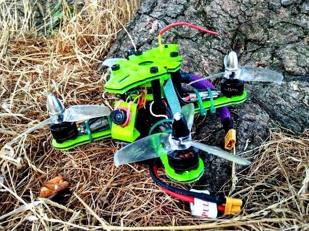
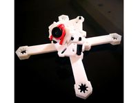
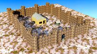
X-132: The Ultimate Sub 250g 2-3 Inch Brushless "Monster Whoop" Micro Drone Frame Kit by Karamvir_Bhagat
by Thingiverse
Last crawled date: 3 years ago
IMPORTANT:
PLEASE READ DESCRIPTION VERY CAREFULLY BEFORE SELECTING PARTS TO PRINT!
STL FILES HAVE BEEN CAREFULLY AND CLEARLY LABELLED AND ORDERED FOR EASE OF REFERENCE. DOWNLOAD THE FULL SET AND THEN SELECT PARTS IN YOUR COMPUTER'S FILE BROWER.
Prototype video: https://www.youtube.com/watch?v=_vkqLQrdgHYRig Upgrade & FPV with my Mum :) https://www.youtube.com/watch?v=SJC-BfLy9Ic
If you enjoyed your experience using this project please do share pictures and media of your build to spread the word. Also for me personally, I think it would just be super cool to see what you make!
13.09.2018 - IMPORTANT UPGRADE TO CAMERA MOUNTS - ADDED CLEARANCE AND ADAPTERS
Note:
This mount is internally cleared for 20 x 20 mm to ensure a clean fit for the camera. The mount can easily be bend to accommodate for any looseness and or you can use thin washer to resolve any issues if you encounter any.
Picking the right file:
There are several files here, they are as follows:
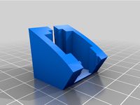
RunCam 19 x 19 Mount - Has a M2 hole on each side to mount 19 x 19 cameras or the provided adapters.
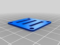
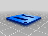
RunCam 19 x 19 Mount - Has M2 slots on each side to mount 19 x 19 cameras or the provided adapters.
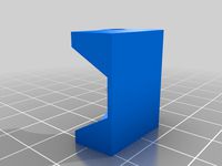
Drop Head RunCam 19 x 19 Mount - Is labelled as such and is smaller than the other mounts. It is such that you should be able to now mount off the roof.
Universal Camera Adapter - By looping a rubber band around the front of the lens, twisting, pulling behind and over your camera and back onto the lens will secure your FPV camera. This is suitable for Tiny Whoop style cameras and offers adjustable tilt. The lens is cleared for 13.8 mm lenses.
Universal Camera Adapter TPU - This is the same as the above file with a smaller lens opening. If printed in TPU you can push fit in your camera. The mount should stretch and grip it. If you have difficultly carefully and safely cut a small slit to expand the hole.
Print Advice:
Place the piece on the bed so that when looking directly down it appears as a C or a U. You should have the print lines running along the long edge of the piece where the camera bolts in.
For the adapter print vertically with the lock points point up off the bed.
Files have been updated and included. Separate files can be found at: https://www.thingiverse.com/thing:3098162
real_darKing kindly made and shared an attractive mount to use on my frames. You can check it out at: https://www.thingiverse.com/thing:3094068
Update: 11.09.2018
New RunCam 19 x 19 - Some users kindly reported that they were having issues with fitment of their RunCam cameras. This new mount has added clearance and should now clearance adequately. It mounts to the frame in the slot with M3 hardware.
For the most strength, print so that the mount:
Appears like a C or U flat on the bed.
Has the layer lines running up the vertical edges with camera mount holes.
real_darKing kindly made and shared an attractive mount to use on my frames. You can check it out at: https://www.thingiverse.com/thing:3094068
You can join the Facebook group at:https://www.facebook.com/groups/254825821981391/
Update: 10.09.2018
If you would like to use a Magnum Mini Stack (as in the Emax Babyhawk R) you will need to use the M2 to M3 adapters. You can mount via the arm holes or by rotating the stack to have one corner facing forward like a Tiny Whoop.
Adapters: https://www.thingiverse.com/thing:3093369
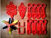
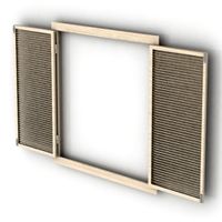
Update: (30/06/2018) I am proud to release the new upgraded design for the quad. The original one piece frames have been retained, the designations for part thickness are as below (1.1 mm, 1.7 mm and 2.8 mm). Support has been added so you can use the design in a modular style and replace arms and experiment with build configurations. This will allow people to now print a drone with different materials for the arms and the body. You can also use thinner plates for strength and aesthetic customization.
Update: (27/06/2018) - I had mentioned making plates for composite/laminate frames. After consideration I concluded that the 2.3 mm plates are redundant. I will therefore be removing these and adding the following designations: 1 mm, 1.7 mm and 2.8 mm. I have also added modular arm support to for all arm sizes in the aforementioned plate thicknesses. The idea is that people can now use the modular set up, for example if they have hard time with warping or for more tricky materials like ABS. The adjusted plate depths are still in perfect proportion, but will allow people to stack and sandwich thinner plates to achieve different frame characteristics visually and in strength. This should hopefully be done shortly. I am currently in the process of converting the files to STL for upload. I will also include the smaller aperture camera mounts as I had forgot to do this earlier. I will also try and produce a parts document with pictures for easier reference
Update Quad Part Recipes:
Files named modular are for modular builds, others are for the uni-body. 2D files have been included to assist in CNC cutting.
Composite/laminate Stacking:
The idea is that 1.1 mm, 1.7 mm and 2.8 mm plates can be stacked and together to create a composite/laminate frame.
I noted that my filament strands in various materials had a lot of flex and less brittleness when I was trying to break them in my hands. I also noted that brims also seemed to flex and twist a lot without breaking easily. The common element seemed to be how thin the material piece was. I therefore made the frame pieces into thin plates so take advantage of these characteristics and have found it to be beneficial to increase strength and reduce vibration.
I have found that even without glue, there is improved flexibility and shock resistance as the presence of multiple layers allow for more give in the parts. Normally the maximum number of layers is 3 due to weight, but you can combine different materials, in different thicknesses, in open and closed faced sandwiches to see what works best for you. I have not tried gluing layers together yet, but this should theoretically give good results.
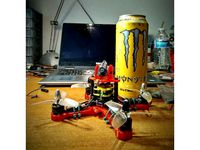
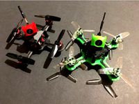
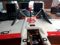
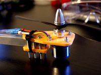
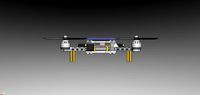
I personally find that a good combination is to print your parts of choice in 1.1 mm and place three plates together. I have had very good success with PLA/TPU/PLA as in the main picture. This gives much more resistance to crashes and also stops arms from getting torn off. The thin plates allow brittle materials like PLA to flex and this same recipe could be improved by using PETG/TPU/PETG.
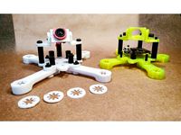
Colourful Building Concept:
Print and attach different combinations of the above to customize the look of your build. Placing spilt and solid arms can create nice colours on the arms of the quad and in the layers of the parts.
Quad Configuration Update:
I got tired of having to reprint the entire frame every time one arm broke so I made it modular. The design is the same and the same options are available. However the X-132 can now be built in virtually every combination including, standard config, pusher and split front/rear. Have fun and see what you create!
File organization: I will be working on a little parts booklet, otherwise, download in full, hit order by name in your browser and the files are labelled in a self explanatory manner. Select and choose what you wish to use
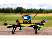
X-132 - The Ultimate Sub-250g, 2 - 3", Fully 3D Printable, Racing Quadcopter Drone
X – 132 Concept:
To produce:
A fully 3D printable quadcopter that performs as well as a quadcopter with a carbon fibre frame.
A quadcopter can be built to have an AUW of less than 250g so as to be light, fun and legal to fly basically anywhere.
A quadcopter with a minimal footprint that can run up to 3” propellers.
A quadcopter that maximizes component compatibility and that can house electronic components up to 30.5mm x 30.5 mm.
A quadcopter that allows pilots the flexibility to build custom craft suited to their needs and preferences.
A quadcopter that’s frame geometry inherently minimizes vibration, maximizes strength, lightness and beneficial flight characteristics.
A quadcopter that is cheap, easy and fun to build and maintain.
Create a free resource for pilots to use to help the flight and FPV community develop and progress.
Key Features Explained:
Fully 3D printable:
Designed to print quickly and with ease. No part of the design should exceed two hours with a reasonably well set up machine.
Minimal need for print supports and bed adhesion aids. This helps to increase print speed and also reduce the likelihood of failed prints and imperfections.
Designed with strength and lightness in mind. This frame compares to carbon frames of similar size in weight and is designed to be suitably strong enough to print in all commonly available printing materials.
Super Compatibility:
Being able to mix and match different components can allow you to create something quite special or simply help you save money by letting you build a fully functional quad using your spare parts.
Frankenquadding for those on a budget.
In short, this frame is compatible with virtually all micro and mini quadcopter components as of the current time (11th June 2018).
Specifically, this frame is compatible with the following:
Flight controllers: 16 mm x 16 mm, 20 mm x 20 mm, 30.5 mm x 30.5 mm.
PDBs: 16 mm x 16 mm, 20 mm x 20 mm, 30.5 mm x 30.5 mm.
ESCs (4 in 1): 16 mm x 16 mm, 20 mm x 20 mm, 30.5 mm x 30.5 mm.
ESC (Arm mount): I have fit 20a with no problem, give your quad some biceps!
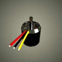
Motors: 11xx, 13xx,14xx in x and + configuration. Yes, you can go fast. Really, really fast!
Propellers: 2” – 3” (with 3 mm clearance!).
Cameras: Run Cam Micro Swift Mount (19 mm x 19 mm). All tiny whoop cameras with the use of individual mounts from 0 – 30 degrees in 5-degree increments. Both utilize M3 hardware and can be used in of your other projects.
VTX: Run Cam TX200 is my preferred VTX of choice. The stack plates will let you put anything you want.
RX: The stack plates will let you put anything you want, Flysky, FrSky, DSM, Divination. Everybody can party.
Component Protection:
The frame has been designed to offer as much protection to components as possible. Note the following design considerations:
Central stack design to allow components to all sit within a very stiff enclosed structure.
Single plate mounting for all flight components to ensure that if the top plate separates, no components will be torn off.
Linked arms to increase stiffness and reduce the likelihood of arm separations that tear off components.
Crumple zones to allow the frame to absorb impacts and not your components.
High shock absorbency and impact energy transference characteristics reduces the likelihood of amperage and voltage spikes that destroy components, by routing stresses around components.
Unique Geometry:
This entire design and all of its accessories are in perfect geometric proportion to one another.
I am a musician, in particular a guitarist. Geometry and proportion are key when considering the transmission of sound, vibration, in an instrument. Good design can help to increase sustain, balance vibrations and enhance desired vibration characteristics.
People spend much time fussing about their PIDs, how things are mounted, etc etc rather than on their actual flying. They also seem to rarely consider how the actual proportions of the frame affects the transmission of vibration.
In short, the frame, if you think about it, is much like a pitch fork. If you can tune the design right, you should theoretically be able to eliminate a significant amount of vibration. Additionally, you should be able to enhance characteristics such as strength and stiffness. When considering that plastics have absorbent qualities with regard to vibration, this benefit should further be enhanced.
The other key aspect to consider is balance. A poorly balanced quad will always be out performed by a well-balanced quad and few designs seem to take this into consideration.
I enjoy flight both fast (racey) and also acrobatically. In the end I wanted a frame which would comfortably bridge both types of flying. This frame is perfectly balanced in all axes and the battery mounting and flight component stack are perfectly centered allowing for the best balance possible.
Additionally, the frame has been made as small as possible to center mass and reduce size and flight drag.
Great care has been taken to produce a design where every single line, of every single component is perfectly in proportion.
The benefits I have noted from this are indeed as described above.
Further development and CNC Cutting:
The 2D STL files have been included to allow people to have frames that they enjoy cut at a CNC workshop local to them in the material of their choice. Hole mounts have been standardised to allow for other designers to create new and original parts to attach to the structure of the design. Users of the design can then print and design whatever accessory parts they wish to use and have quad that they can use for a long time.
Originality of design, copy protection, legal declaration and disclaimer:
Very important to me personally, is the originality of design. I have taken great care to make a totally unique and original design that does not take from anyone else’s work or infringes on any copyrights or patents.
The unique geometry of this design alongside its unique design features identifies it as an original design and also builds in copy protection. If there is any duplication of any part of this design, a measurement can be taken of any two points and by simple calculation it can be proved.
I am a British citizen and this design was produced in the United Kingdom. The natural design rights reside with me as accorded by European Union law.
Just as a polite warning to anyone, I am legally trained and have worked in the legal sector as paralegal for almost a decade.
Legal Declaration – Originality of design:
I hereby state that I am the sole author of this work, that it is an original creation and not a duplication in any form.
Legal Disclaimer:
I accept no liability for damage, harm, injury or death caused to anything by the use of this design.
You use this design at your own risk.
Printing advice:
Plastic Selection:
PLA – The 19mm and 15 mm versions should be adequately strong if you’re are flying in a grassy area and in concrete areas if you are careful. The problem with PLA is the brittleness so appropriately choose frame depth to suit your needs.
PETG – The flexible nature and relative of PETG make it an ideal candidate for plastic choice. I have flown several of these frames in PETG and the strength increase is significant alongside the vibration absorption. If you have an F4 series flight controller, it would benefit to print in this material. The flexible nature will allow for maximum strength for the slimmer armed variants.
ABS – I have not been able to test in ABS, but considering it is the strongest of the three primarily accessible/popular plastics and should produce the strongest frames/components.
Tolerance & fitment:
There are only two hole sizes in this entire design, M2 and M3. Everybody has different tolerances on their machines so I have left the measurements exact. To compensate for tolerance, adjust the scaling on your software.
Parts Reference List and build advice:
Frames:
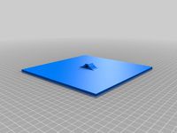
2D – These STL files have been included to allow people to have frames cut for themselves at a facility close to them. Alternatively you can use the design software of your choice to pull into three dimensions to desired thickness or simply to have a 2D blank to work on.
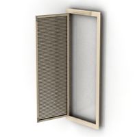
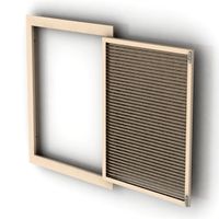
3D – The bottom and top plates have been made in the following thicknesses, 1.7 mm, 2.3 mm and 2.8 mm. This is to account for variability in plastic strength, flexibility and stresses incurred as a result of having split arms. Print as you feel appropriate to your craft and flight skill capacity. I would suggest sticking to the thicker frames, particularly when using the split arm versions.
Variations:
The frames are identical save for the fact that they have varying arm widths. There are three designations 19 mm, 15 mm and 12 mm, each with a split arm option. The split arm introduces a recess into the frame to reduce weight and drag.
19 mm arms - These frames will offer the most air resistance, but likely the most strength. If you bump into shit a lot, this would be a good choice. This would be most suitable for printing applications and a super durable carbon cut.
15 mm arms – These offer similar strength to the 19 mm frames but have the benefits of reduced weight. If you are a better pilot and really want to make your craft perform, this would be a good option. I would say that these would make nice frames in a carbon fibre cut.
12 mm arms – These frames are experimental as I have not personally tested them. I did create them for those who are experienced pilots wanting to test the limits of speed. I would say that these would make nice frames in a carbon fibre cut.
Stack configuration:
My personal preference is to mount my flight controller at the bottom of the stack, have my receiver in the middle and my VTX on the top so that I can easily change the channel. The stack plates should allow you to foam tape, zip/cable tie and wire secure components to your heart’s content.
Mounting in a stack, preferably off the bottom plate will help to protect the majority of your components during crashes.
Camera Mounting:
You will note a slot in the frame. This M3 slot is designed to hold the camera mounts and allows you to move the mount to the position of your choice to suit component spacing and camera view.
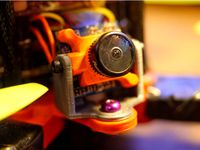
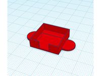
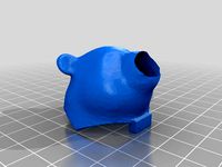
Angled camera mount:
There are two variations, one with a 12 mm and one with a 10.8 mm aperture. You can use basically any micro FPV camera in this mount. Print with the print lines running up the mounts vertically for the most strength.
To mount put your camera lens through the hole. If it does not fit, unscrew the lens and then re-screw passing it through the hole. Once through get a small rubber band, loop over the lens, twist and pull around the back of the camera. Loop the other end over the lens and you are done! Adding a little strip of foam tape to the back of the mount can help to adhere your camera and reduce any vibrations.
To mount to the frame, pop a screw through and put some double-sided foam tape on the bottom to secure and to soft mount the mount.
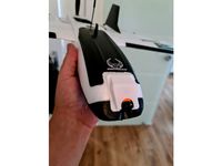
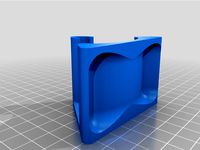
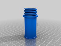
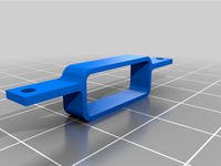
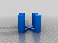
Run Cam Mount:
The mount is internally clearance for 19 mm x 19 mm to suit the micro swift 2. This mount screws to the frame with an M3 bolt/screw. Print so that the print lines run along the vertical sides of the mount, this will maximize strength. Place some double-sided foam tape on the bottom of the mount and you will have a very secure mount and free camera soft mounting.
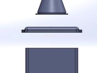
Top plate mounting:
There are two top plates, I have affectionately dubbed them the sunroof and hardtop. The reason for the name is likely obvious once you look at the pieces, but it is to allow you to put your VTX (if you chose to run a separated unit, as is my preference) at the top of your stack and have access to the button to change channels. You can alternatively glue in a buzzer if you wish.
You will note a number of holes cut into the frame. All are functional, the majority of which are to mount various flight stack components. Your top plate standoff configuration will largely depend on your build. I normally use the front two mounts holes or the 30.5 x 30.5 mounts holes with one standoff in the back. It makes a triangle if you look down at the quad. This normally allows me the space to house my components and to hold my battery lead in place in the rear. It is very strong in collisions and I would say better than square, four standoff setups.
You will note that I have included mount holes on the top plate. Apart from providing mounting flexibility this is to allow other designers to have standard mount sizes to produce additional component mounts such as mounts for buzzers, led, aerial and GPS units. These holes have also been left so that the lazy, like me, can run their aerial out of the top without additional fixtures.
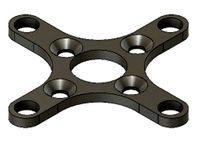
Motor mounting and shim plates:
This frame has motor mounts that accommodate 9 mm – 12 mm mounting holes in M2. Most motors are supplied with oversized M2.5 bolts whilst the plans available specify M2 holes. You can therefore mount your motors as you wish. I have included shim plates in 1.0 mm and 0.5 mm to allow people to use different hardware.
Personal notes and preferences:
I have included my personal preferences to help guide you in deciding what combination of parts to utilize and to help you understand and get the most out of the design.
My personal preference is to fly with separate ESCs and an all in one flight controller. I like the Omnibus F3 Nano, but you could happily use what you like such as the ever popular Piko BLX.
I do like 4 in 1 esc’s but for the sake of a little more wiring, the money saving when a unit fails is a deal breaker. The exception I find is when I am really strapped for space and weight in a build.
The design was therefore originally intended to have esc on the arms. I have offered split and slimmed arm variations for those who wish to use 4 in 1 speed controllers or who want to keep AUW to a minimum. These designs were intended to take advantage of weight and drag savings whilst also making use of the flexible nature of plastics to add strength. Surprisingly I was finding that thinner sections on the arms allowed certain plastics to flex rather than snap and you may also note this in your builds.
Personally, I have noted that the best balance and component protection comes from placing things in central stack and using an appropriate combination of standoffs to mount the top plate. It also makes wiring relatively straight forward.
Plastic is not carbon fibre and you will have to rebuild, probably quite a bit depending on your flight skill and plastic choice. I therefore wanted people to give people the opportunity to have fun with their builds rather than it being a tedious exercise.
I therefore made the variations that I feel my fellow pilots would request. Some of the frames are more experimental but are suitable for things like speed testing and drag racing. I have included the 2D STL files so that you can go to your local CNC service and request them cut it in the material of your choice such as carbon fibre. Alternatively, if you are good with design software you could use this to remix a design for yourself or to pull into 3 dimensions a frame to your desired thickness.
I normally fly the 19mm and 15 mm frames solid and split. Once I get some time I will do some more testing with the 12 mm versions. I feel that for carbon cuts, this will be the most popular due to the low drag and weight that it offers. But don’t wait for me, get printing and let me know!
So, when you build, see what you like and have fun! I have only tried standard set-ups, but you could even build this as a pusher or with two bottom plates. Indulge your curiosity, have fun and see what you can create! I would love to see what flies of your imagination!
You may/will need:
M2/M3 standoffs. Nylon for weight reduction purposes.
Zip/Cable ties.
Rubber bands.
Double sided tape.
Double sided foam tape.
Foam.
PLEASE READ DESCRIPTION VERY CAREFULLY BEFORE SELECTING PARTS TO PRINT!
STL FILES HAVE BEEN CAREFULLY AND CLEARLY LABELLED AND ORDERED FOR EASE OF REFERENCE. DOWNLOAD THE FULL SET AND THEN SELECT PARTS IN YOUR COMPUTER'S FILE BROWER.
Prototype video: https://www.youtube.com/watch?v=_vkqLQrdgHYRig Upgrade & FPV with my Mum :) https://www.youtube.com/watch?v=SJC-BfLy9Ic
If you enjoyed your experience using this project please do share pictures and media of your build to spread the word. Also for me personally, I think it would just be super cool to see what you make!
13.09.2018 - IMPORTANT UPGRADE TO CAMERA MOUNTS - ADDED CLEARANCE AND ADAPTERS
Note:
This mount is internally cleared for 20 x 20 mm to ensure a clean fit for the camera. The mount can easily be bend to accommodate for any looseness and or you can use thin washer to resolve any issues if you encounter any.
Picking the right file:
There are several files here, they are as follows:
RunCam 19 x 19 Mount - Has a M2 hole on each side to mount 19 x 19 cameras or the provided adapters.
RunCam 19 x 19 Mount - Has M2 slots on each side to mount 19 x 19 cameras or the provided adapters.
Drop Head RunCam 19 x 19 Mount - Is labelled as such and is smaller than the other mounts. It is such that you should be able to now mount off the roof.
Universal Camera Adapter - By looping a rubber band around the front of the lens, twisting, pulling behind and over your camera and back onto the lens will secure your FPV camera. This is suitable for Tiny Whoop style cameras and offers adjustable tilt. The lens is cleared for 13.8 mm lenses.
Universal Camera Adapter TPU - This is the same as the above file with a smaller lens opening. If printed in TPU you can push fit in your camera. The mount should stretch and grip it. If you have difficultly carefully and safely cut a small slit to expand the hole.
Print Advice:
Place the piece on the bed so that when looking directly down it appears as a C or a U. You should have the print lines running along the long edge of the piece where the camera bolts in.
For the adapter print vertically with the lock points point up off the bed.
Files have been updated and included. Separate files can be found at: https://www.thingiverse.com/thing:3098162
real_darKing kindly made and shared an attractive mount to use on my frames. You can check it out at: https://www.thingiverse.com/thing:3094068
Update: 11.09.2018
New RunCam 19 x 19 - Some users kindly reported that they were having issues with fitment of their RunCam cameras. This new mount has added clearance and should now clearance adequately. It mounts to the frame in the slot with M3 hardware.
For the most strength, print so that the mount:
Appears like a C or U flat on the bed.
Has the layer lines running up the vertical edges with camera mount holes.
real_darKing kindly made and shared an attractive mount to use on my frames. You can check it out at: https://www.thingiverse.com/thing:3094068
You can join the Facebook group at:https://www.facebook.com/groups/254825821981391/
Update: 10.09.2018
If you would like to use a Magnum Mini Stack (as in the Emax Babyhawk R) you will need to use the M2 to M3 adapters. You can mount via the arm holes or by rotating the stack to have one corner facing forward like a Tiny Whoop.
Adapters: https://www.thingiverse.com/thing:3093369
Update: (30/06/2018) I am proud to release the new upgraded design for the quad. The original one piece frames have been retained, the designations for part thickness are as below (1.1 mm, 1.7 mm and 2.8 mm). Support has been added so you can use the design in a modular style and replace arms and experiment with build configurations. This will allow people to now print a drone with different materials for the arms and the body. You can also use thinner plates for strength and aesthetic customization.
Update: (27/06/2018) - I had mentioned making plates for composite/laminate frames. After consideration I concluded that the 2.3 mm plates are redundant. I will therefore be removing these and adding the following designations: 1 mm, 1.7 mm and 2.8 mm. I have also added modular arm support to for all arm sizes in the aforementioned plate thicknesses. The idea is that people can now use the modular set up, for example if they have hard time with warping or for more tricky materials like ABS. The adjusted plate depths are still in perfect proportion, but will allow people to stack and sandwich thinner plates to achieve different frame characteristics visually and in strength. This should hopefully be done shortly. I am currently in the process of converting the files to STL for upload. I will also include the smaller aperture camera mounts as I had forgot to do this earlier. I will also try and produce a parts document with pictures for easier reference
Update Quad Part Recipes:
Files named modular are for modular builds, others are for the uni-body. 2D files have been included to assist in CNC cutting.
Composite/laminate Stacking:
The idea is that 1.1 mm, 1.7 mm and 2.8 mm plates can be stacked and together to create a composite/laminate frame.
I noted that my filament strands in various materials had a lot of flex and less brittleness when I was trying to break them in my hands. I also noted that brims also seemed to flex and twist a lot without breaking easily. The common element seemed to be how thin the material piece was. I therefore made the frame pieces into thin plates so take advantage of these characteristics and have found it to be beneficial to increase strength and reduce vibration.
I have found that even without glue, there is improved flexibility and shock resistance as the presence of multiple layers allow for more give in the parts. Normally the maximum number of layers is 3 due to weight, but you can combine different materials, in different thicknesses, in open and closed faced sandwiches to see what works best for you. I have not tried gluing layers together yet, but this should theoretically give good results.
I personally find that a good combination is to print your parts of choice in 1.1 mm and place three plates together. I have had very good success with PLA/TPU/PLA as in the main picture. This gives much more resistance to crashes and also stops arms from getting torn off. The thin plates allow brittle materials like PLA to flex and this same recipe could be improved by using PETG/TPU/PETG.
Colourful Building Concept:
Print and attach different combinations of the above to customize the look of your build. Placing spilt and solid arms can create nice colours on the arms of the quad and in the layers of the parts.
Quad Configuration Update:
I got tired of having to reprint the entire frame every time one arm broke so I made it modular. The design is the same and the same options are available. However the X-132 can now be built in virtually every combination including, standard config, pusher and split front/rear. Have fun and see what you create!
File organization: I will be working on a little parts booklet, otherwise, download in full, hit order by name in your browser and the files are labelled in a self explanatory manner. Select and choose what you wish to use
X-132 - The Ultimate Sub-250g, 2 - 3", Fully 3D Printable, Racing Quadcopter Drone
X – 132 Concept:
To produce:
A fully 3D printable quadcopter that performs as well as a quadcopter with a carbon fibre frame.
A quadcopter can be built to have an AUW of less than 250g so as to be light, fun and legal to fly basically anywhere.
A quadcopter with a minimal footprint that can run up to 3” propellers.
A quadcopter that maximizes component compatibility and that can house electronic components up to 30.5mm x 30.5 mm.
A quadcopter that allows pilots the flexibility to build custom craft suited to their needs and preferences.
A quadcopter that’s frame geometry inherently minimizes vibration, maximizes strength, lightness and beneficial flight characteristics.
A quadcopter that is cheap, easy and fun to build and maintain.
Create a free resource for pilots to use to help the flight and FPV community develop and progress.
Key Features Explained:
Fully 3D printable:
Designed to print quickly and with ease. No part of the design should exceed two hours with a reasonably well set up machine.
Minimal need for print supports and bed adhesion aids. This helps to increase print speed and also reduce the likelihood of failed prints and imperfections.
Designed with strength and lightness in mind. This frame compares to carbon frames of similar size in weight and is designed to be suitably strong enough to print in all commonly available printing materials.
Super Compatibility:
Being able to mix and match different components can allow you to create something quite special or simply help you save money by letting you build a fully functional quad using your spare parts.
Frankenquadding for those on a budget.
In short, this frame is compatible with virtually all micro and mini quadcopter components as of the current time (11th June 2018).
Specifically, this frame is compatible with the following:
Flight controllers: 16 mm x 16 mm, 20 mm x 20 mm, 30.5 mm x 30.5 mm.
PDBs: 16 mm x 16 mm, 20 mm x 20 mm, 30.5 mm x 30.5 mm.
ESCs (4 in 1): 16 mm x 16 mm, 20 mm x 20 mm, 30.5 mm x 30.5 mm.
ESC (Arm mount): I have fit 20a with no problem, give your quad some biceps!
Motors: 11xx, 13xx,14xx in x and + configuration. Yes, you can go fast. Really, really fast!
Propellers: 2” – 3” (with 3 mm clearance!).
Cameras: Run Cam Micro Swift Mount (19 mm x 19 mm). All tiny whoop cameras with the use of individual mounts from 0 – 30 degrees in 5-degree increments. Both utilize M3 hardware and can be used in of your other projects.
VTX: Run Cam TX200 is my preferred VTX of choice. The stack plates will let you put anything you want.
RX: The stack plates will let you put anything you want, Flysky, FrSky, DSM, Divination. Everybody can party.
Component Protection:
The frame has been designed to offer as much protection to components as possible. Note the following design considerations:
Central stack design to allow components to all sit within a very stiff enclosed structure.
Single plate mounting for all flight components to ensure that if the top plate separates, no components will be torn off.
Linked arms to increase stiffness and reduce the likelihood of arm separations that tear off components.
Crumple zones to allow the frame to absorb impacts and not your components.
High shock absorbency and impact energy transference characteristics reduces the likelihood of amperage and voltage spikes that destroy components, by routing stresses around components.
Unique Geometry:
This entire design and all of its accessories are in perfect geometric proportion to one another.
I am a musician, in particular a guitarist. Geometry and proportion are key when considering the transmission of sound, vibration, in an instrument. Good design can help to increase sustain, balance vibrations and enhance desired vibration characteristics.
People spend much time fussing about their PIDs, how things are mounted, etc etc rather than on their actual flying. They also seem to rarely consider how the actual proportions of the frame affects the transmission of vibration.
In short, the frame, if you think about it, is much like a pitch fork. If you can tune the design right, you should theoretically be able to eliminate a significant amount of vibration. Additionally, you should be able to enhance characteristics such as strength and stiffness. When considering that plastics have absorbent qualities with regard to vibration, this benefit should further be enhanced.
The other key aspect to consider is balance. A poorly balanced quad will always be out performed by a well-balanced quad and few designs seem to take this into consideration.
I enjoy flight both fast (racey) and also acrobatically. In the end I wanted a frame which would comfortably bridge both types of flying. This frame is perfectly balanced in all axes and the battery mounting and flight component stack are perfectly centered allowing for the best balance possible.
Additionally, the frame has been made as small as possible to center mass and reduce size and flight drag.
Great care has been taken to produce a design where every single line, of every single component is perfectly in proportion.
The benefits I have noted from this are indeed as described above.
Further development and CNC Cutting:
The 2D STL files have been included to allow people to have frames that they enjoy cut at a CNC workshop local to them in the material of their choice. Hole mounts have been standardised to allow for other designers to create new and original parts to attach to the structure of the design. Users of the design can then print and design whatever accessory parts they wish to use and have quad that they can use for a long time.
Originality of design, copy protection, legal declaration and disclaimer:
Very important to me personally, is the originality of design. I have taken great care to make a totally unique and original design that does not take from anyone else’s work or infringes on any copyrights or patents.
The unique geometry of this design alongside its unique design features identifies it as an original design and also builds in copy protection. If there is any duplication of any part of this design, a measurement can be taken of any two points and by simple calculation it can be proved.
I am a British citizen and this design was produced in the United Kingdom. The natural design rights reside with me as accorded by European Union law.
Just as a polite warning to anyone, I am legally trained and have worked in the legal sector as paralegal for almost a decade.
Legal Declaration – Originality of design:
I hereby state that I am the sole author of this work, that it is an original creation and not a duplication in any form.
Legal Disclaimer:
I accept no liability for damage, harm, injury or death caused to anything by the use of this design.
You use this design at your own risk.
Printing advice:
Plastic Selection:
PLA – The 19mm and 15 mm versions should be adequately strong if you’re are flying in a grassy area and in concrete areas if you are careful. The problem with PLA is the brittleness so appropriately choose frame depth to suit your needs.
PETG – The flexible nature and relative of PETG make it an ideal candidate for plastic choice. I have flown several of these frames in PETG and the strength increase is significant alongside the vibration absorption. If you have an F4 series flight controller, it would benefit to print in this material. The flexible nature will allow for maximum strength for the slimmer armed variants.
ABS – I have not been able to test in ABS, but considering it is the strongest of the three primarily accessible/popular plastics and should produce the strongest frames/components.
Tolerance & fitment:
There are only two hole sizes in this entire design, M2 and M3. Everybody has different tolerances on their machines so I have left the measurements exact. To compensate for tolerance, adjust the scaling on your software.
Parts Reference List and build advice:
Frames:
2D – These STL files have been included to allow people to have frames cut for themselves at a facility close to them. Alternatively you can use the design software of your choice to pull into three dimensions to desired thickness or simply to have a 2D blank to work on.
3D – The bottom and top plates have been made in the following thicknesses, 1.7 mm, 2.3 mm and 2.8 mm. This is to account for variability in plastic strength, flexibility and stresses incurred as a result of having split arms. Print as you feel appropriate to your craft and flight skill capacity. I would suggest sticking to the thicker frames, particularly when using the split arm versions.
Variations:
The frames are identical save for the fact that they have varying arm widths. There are three designations 19 mm, 15 mm and 12 mm, each with a split arm option. The split arm introduces a recess into the frame to reduce weight and drag.
19 mm arms - These frames will offer the most air resistance, but likely the most strength. If you bump into shit a lot, this would be a good choice. This would be most suitable for printing applications and a super durable carbon cut.
15 mm arms – These offer similar strength to the 19 mm frames but have the benefits of reduced weight. If you are a better pilot and really want to make your craft perform, this would be a good option. I would say that these would make nice frames in a carbon fibre cut.
12 mm arms – These frames are experimental as I have not personally tested them. I did create them for those who are experienced pilots wanting to test the limits of speed. I would say that these would make nice frames in a carbon fibre cut.
Stack configuration:
My personal preference is to mount my flight controller at the bottom of the stack, have my receiver in the middle and my VTX on the top so that I can easily change the channel. The stack plates should allow you to foam tape, zip/cable tie and wire secure components to your heart’s content.
Mounting in a stack, preferably off the bottom plate will help to protect the majority of your components during crashes.
Camera Mounting:
You will note a slot in the frame. This M3 slot is designed to hold the camera mounts and allows you to move the mount to the position of your choice to suit component spacing and camera view.
Angled camera mount:
There are two variations, one with a 12 mm and one with a 10.8 mm aperture. You can use basically any micro FPV camera in this mount. Print with the print lines running up the mounts vertically for the most strength.
To mount put your camera lens through the hole. If it does not fit, unscrew the lens and then re-screw passing it through the hole. Once through get a small rubber band, loop over the lens, twist and pull around the back of the camera. Loop the other end over the lens and you are done! Adding a little strip of foam tape to the back of the mount can help to adhere your camera and reduce any vibrations.
To mount to the frame, pop a screw through and put some double-sided foam tape on the bottom to secure and to soft mount the mount.
Run Cam Mount:
The mount is internally clearance for 19 mm x 19 mm to suit the micro swift 2. This mount screws to the frame with an M3 bolt/screw. Print so that the print lines run along the vertical sides of the mount, this will maximize strength. Place some double-sided foam tape on the bottom of the mount and you will have a very secure mount and free camera soft mounting.
Top plate mounting:
There are two top plates, I have affectionately dubbed them the sunroof and hardtop. The reason for the name is likely obvious once you look at the pieces, but it is to allow you to put your VTX (if you chose to run a separated unit, as is my preference) at the top of your stack and have access to the button to change channels. You can alternatively glue in a buzzer if you wish.
You will note a number of holes cut into the frame. All are functional, the majority of which are to mount various flight stack components. Your top plate standoff configuration will largely depend on your build. I normally use the front two mounts holes or the 30.5 x 30.5 mounts holes with one standoff in the back. It makes a triangle if you look down at the quad. This normally allows me the space to house my components and to hold my battery lead in place in the rear. It is very strong in collisions and I would say better than square, four standoff setups.
You will note that I have included mount holes on the top plate. Apart from providing mounting flexibility this is to allow other designers to have standard mount sizes to produce additional component mounts such as mounts for buzzers, led, aerial and GPS units. These holes have also been left so that the lazy, like me, can run their aerial out of the top without additional fixtures.
Motor mounting and shim plates:
This frame has motor mounts that accommodate 9 mm – 12 mm mounting holes in M2. Most motors are supplied with oversized M2.5 bolts whilst the plans available specify M2 holes. You can therefore mount your motors as you wish. I have included shim plates in 1.0 mm and 0.5 mm to allow people to use different hardware.
Personal notes and preferences:
I have included my personal preferences to help guide you in deciding what combination of parts to utilize and to help you understand and get the most out of the design.
My personal preference is to fly with separate ESCs and an all in one flight controller. I like the Omnibus F3 Nano, but you could happily use what you like such as the ever popular Piko BLX.
I do like 4 in 1 esc’s but for the sake of a little more wiring, the money saving when a unit fails is a deal breaker. The exception I find is when I am really strapped for space and weight in a build.
The design was therefore originally intended to have esc on the arms. I have offered split and slimmed arm variations for those who wish to use 4 in 1 speed controllers or who want to keep AUW to a minimum. These designs were intended to take advantage of weight and drag savings whilst also making use of the flexible nature of plastics to add strength. Surprisingly I was finding that thinner sections on the arms allowed certain plastics to flex rather than snap and you may also note this in your builds.
Personally, I have noted that the best balance and component protection comes from placing things in central stack and using an appropriate combination of standoffs to mount the top plate. It also makes wiring relatively straight forward.
Plastic is not carbon fibre and you will have to rebuild, probably quite a bit depending on your flight skill and plastic choice. I therefore wanted people to give people the opportunity to have fun with their builds rather than it being a tedious exercise.
I therefore made the variations that I feel my fellow pilots would request. Some of the frames are more experimental but are suitable for things like speed testing and drag racing. I have included the 2D STL files so that you can go to your local CNC service and request them cut it in the material of your choice such as carbon fibre. Alternatively, if you are good with design software you could use this to remix a design for yourself or to pull into 3 dimensions a frame to your desired thickness.
I normally fly the 19mm and 15 mm frames solid and split. Once I get some time I will do some more testing with the 12 mm versions. I feel that for carbon cuts, this will be the most popular due to the low drag and weight that it offers. But don’t wait for me, get printing and let me know!
So, when you build, see what you like and have fun! I have only tried standard set-ups, but you could even build this as a pusher or with two bottom plates. Indulge your curiosity, have fun and see what you can create! I would love to see what flies of your imagination!
You may/will need:
M2/M3 standoffs. Nylon for weight reduction purposes.
Zip/Cable ties.
Rubber bands.
Double sided tape.
Double sided foam tape.
Foam.
Similar models
thingiverse
free
X-82 "Monster Whoop" - 1.9 - 2.5 Inch Micro Brushless FPV Racing Drone Quadcopter by Karamvir_Bhagat
...y and all liability is with you the user.
you use this design at your own risk and are responsible for any consequences as such.
thingiverse
free
M2 & M2.5 to M3 Adapters & Soft Mounts (20 x 20 mm Flight Controllers) by Karamvir_Bhagat
... rotate and mount the stack like a tiny whoop with a corner facing forward to in the regular manner by mounting through the arms.
thingiverse
free
X-129R "Monster Whoop" - Micro Brushless 3D Printed FPV Quadcopter Drone Frame Kit by Karamvir_Bhagat
...ny and all liability is with you the user.
you use this design at your own risk and are responsible for any consequences as such.
thingiverse
free
X-814 Singularity Master Monster Whoop by Karamvir_Bhagat
... builds.
fully enclosed stack.
height adjustable 19 x 19 camera compatible with 1 mm clearance added.
beast mode built in.
thingiverse
free
Flight Stack Separator by pavalige
...eparate and hold together components in the flight stack.
fits 36 mm boards with 30.5 mm hole spaces.
added a 20 x 20 version too
thingiverse
free
X-120 - 2 Inch "Monster Whoop" Micro Brushless Racing Drone Quadcopter by Karamvir_Bhagat
...just quickly and easily sketch something up for yourself. similary, if you want to have holes instead of slots...
thingiverse
free
X-107 - 2" Micro Brushless Drone Beta Testing by Karamvir_Bhagat
...ers note:
thank you very much your interest and for your participation should you wish to engage in the project!
karamvir bhagat
thingiverse
free
Comp 108 Micro Quad Frame by HalfAshby
...halfashby/designs
also, check out max's design for a camera mounting solution here: https://www.thingiverse.com/thing:2561423
thingiverse
free
FC Stack plate for TBS Crossfire Micro Receiver by shabbirun
...your tbs crossfire micro receiver on. it will just fit on top of your stack and you can zip tie the receiver onto the center bar.
thingiverse
free
Axel's modular 3D printed quadcopter (wooden arms) by Axbri
...the same as my other quadcopter design with carbon fibre motor arms. check it out here: https://www.thingiverse.com/thing:2427724
Karamvir
thingiverse
free
Runcam Micro Sparrow Holder for X-153 and other similar Frames by real_darKing
...the x-153 abd x-132, a 3d printable frame by karamvir bhagat https://www.thingiverse.com/thing:3079727https://www.thingiverse.com/thing:2956351 thank you! about the thing: i wanted...
thingiverse
free
X-107 - 2" Micro Brushless Drone Beta Testing by Karamvir_Bhagat
...ers note:
thank you very much your interest and for your participation should you wish to engage in the project!
karamvir bhagat
thingiverse
free
X-120 - 2 Inch "Monster Whoop" Micro Brushless Racing Drone Quadcopter by Karamvir_Bhagat
... you the user.
you use this design at your own risk and are responsible for any consequences as such.
with love - karamvir bhagat
thingiverse
free
XC-120 Patriot - Micro Brushless 2.5 inch "Monster Whoop" 3D Printable Quadcopter Drone by Karamvir_Bhagat
... you the user.
you use this design at your own risk and are responsible for any consequences as such.
with love - karamvir bhagat
Bhagat
3d_sky
$8

Roman shades of velvet
...fill your room and provide its originality and splendor bhagat ...
thingiverse
free
Runcam Micro Sparrow Holder for X-153 and other similar Frames by real_darKing
...x-153 abd x-132, a 3d printable frame by karamvir bhagat https://www.thingiverse.com/thing:3079727https://www.thingiverse.com/thing:2956351 thank you! about the thing: i wanted to...
thingiverse
free
X-107 - 2" Micro Brushless Drone Beta Testing by Karamvir_Bhagat
...ers note:
thank you very much your interest and for your participation should you wish to engage in the project!
karamvir bhagat
thingiverse
free
X-120 - 2 Inch "Monster Whoop" Micro Brushless Racing Drone Quadcopter by Karamvir_Bhagat
... you the user.
you use this design at your own risk and are responsible for any consequences as such.
with love - karamvir bhagat
thingiverse
free
XC-120 Patriot - Micro Brushless 2.5 inch "Monster Whoop" 3D Printable Quadcopter Drone by Karamvir_Bhagat
... you the user.
you use this design at your own risk and are responsible for any consequences as such.
with love - karamvir bhagat
cg_trader
$20
Bhagat Singh | 3D
...3d print, bhagat singh figurine. bhagat singh bust. bhagat singh stl bhagat singh bhagatsingh revolutionary indian art sculptures
grabcad
free

Logo SD Bhagat
...logo sd bhagat
grabcad
that is my logo, for my vehicle.
grabcad
free

SCREW JACK By Dipraj Bhagat
...
to remove tyre it needs to lift vehicle upwards this jack helps to lift the vehicle upwards and makes tyre removal process easy
3dwarehouse
free
bhautik bhagat fc
...bhautik bhagat fc
3dwarehouse
3dwarehouse
free

bhautik bhagat 2
...bhautik bhagat 2
3dwarehouse
250G
thingiverse
free
Dart 250G Hatch Cover
...dart 250g hatch cover
thingiverse
hatch cover for the zohd dart 250g as an alternative to the standard 3m sticker.
thingiverse
free
ZOHD 250G cam cover by dergringo
...zohd 250g cam cover by dergringo
thingiverse
zohd 250g cam cover
thingiverse
free
ZOHD 250g Micro Cam Mount
...zohd 250g micro cam mount
thingiverse
zohd 250g micro cam mount
thingiverse
free
ZOHD Dart 250G
...zohd dart 250g
thingiverse
dji camera support
dji air unit support
thingiverse
free
ZOHD Dart 250g gps holder by shurikss123
...zohd dart 250g gps holder by shurikss123
thingiverse
zohd dart 250g gps holder
thingiverse
free
250g filament spool flange by Latay
...adka na małą rolkę filamentu (250g, 125mm średnicy)
zapobiega samoistnemu 'odrolowaniu się' filamentu podczas drukowania.
thingiverse
free
ZOHD Dart 250G GPS Mount
...g gps mount
thingiverse
designed for the beitian bn-180 micro gps on my zohd dart 250g flying wing.
https://youtu.be/8jr5izjzza4
thingiverse
free
ZOHD Talon 250g Wall Mount by nmaggioni
...lon 250g wall mount by nmaggioni
thingiverse
wall mount for the zohd talon 250g. refer to the bigger talon gt mount for details.
thingiverse
free
Spool Holder 250g Solder by GuarddogTryker
...r 250g solder spools. no more, no less, just what is needed to get a spool of solder to behave for that next electronics project.
thingiverse
free
Simple 250g spool filament holder by Symix7
...imple filament holder on ender 3/3pro for these little 250g spools.
31mm diameter, 47mm deep.
fitts in original mounting bracket.
Whoop
thingiverse
free
whoop by MichaelJFPV
...whoop by michaeljfpv
thingiverse
whoop
thingiverse
free
Tiny Whoop holder for 2 whoops by d2000
...tiny whoop holder for 2 whoops by d2000
thingiverse
tiny whoop holder for 2 whoop mini drones and battery
thingiverse
free
Whoop frame by Brassekongo
...whoop frame by brassekongo
thingiverse
a tiny whoop frame
thingiverse
free
Whoop frame by Brassekongo
...whoop frame by brassekongo
thingiverse
my first whoop frame.
thingiverse
free
WHOOPS 4
...
whoops is another
big cinewhoop as addon for hyperlite tooth fairy race frame 4"
first flight https://youtu.be/xm9afwiiass
thingiverse
free
Tiny Whoop 65mm by binaryfpv
...tiny whoop 65mm by binaryfpv
thingiverse
tiny whoop 65mm
thingiverse
free
V-Tail Whoop by Mystereon
...v-tail whoop by mystereon
thingiverse
v-tail whoop .. wip
thingiverse
free
Tiny Whoop Case by 3DRCStore
...tiny whoop case by 3drcstore
thingiverse
tiny whoop case for transport.
thingiverse
free
Tiny Whoop Calibration Base
...tiny whoop calibration base
thingiverse
a base usefull to calibrate your tiny whoop
thingiverse
free
Tiny Whoop Gate by Imozeb
...tiny whoop gate by imozeb
thingiverse
custom tiny whoop gate. requires hot glue for assembly.
132
design_connected
$11
Simpliciter 132
...simpliciter 132
designconnected
maxalto simpliciter 132 computer generated 3d model. designed by citterio, antonio.
evermotion
$7
railing 132 am79
...key sculptures 132 am79 railing
highly detailed architecture railing with all textures and materials.. evermotion 3d models shop.
evermotion
$120

Archmodels vol. 132
...tural visualizations. this collection comes with low poly cars models with all textures and materials. evermotion 3d models shop.
evermotion
$7
chair 132 AM147
...model of chair with textures, shaders and materials. it is ready to use, just put it into your scene.. evermotion 3d models shop.
turbosquid
$8
ASRAAM AIM-132
...d
royalty free 3d model asraam aim-132 for download as blend on turbosquid: 3d models for games, architecture, videos. (1631081)
evermotion
$15
rocks 132 am126
...s with ivy with all textures, shaders and materials. it is ready to use, just put it into your scene.. evermotion 3d models shop.
evermotion
$14
Furniture 132 AM29
...el of sofa with all textures, shaders and materials. it is ready to use, just put it into your scene.. evermotion 3d models shop.
turbosquid
$7
Rug Set 132
...y free 3d model rug set 132 for download as max, obj, and fbx on turbosquid: 3d models for games, architecture, videos. (1434644)
turbosquid
free
Free Chair - 132
... available on turbo squid, the world's leading provider of digital 3d models for visualization, films, television, and games.
evermotion
$8
kitchen furniture 132 am10
... furniture with all textures, shaders and materials. it is ready to use, just put it into your scene.. evermotion 3d models shop.
Brushless
turbosquid
$4
Brushless motor
...r download as 3ds, dxf, obj, xsi, wrl, fbx, dwg, dae, and skp on turbosquid: 3d models for games, architecture, videos. (1366202)
3d_export
$10
wheel and motor for mars rover
...last project: a mars rover concept. complete wheel and brushless electrical motor designed to attach to an atv or...
3d_export
$100
the volt futuristic ev hypercar
...future ! some design aspects : this is in-wheel (brushless hub) motors vehicle, for each motor the core part...
3d_export
$20
si cantik cargo plane for humanity medicine kit
...used for the tailboom. the electronic components used are brushless motor os 1000kv which can produce thrust 3kgas a...
free3d
free
N6375 Brushless Motor
...n6375 brushless motor
free3d
n6375 brushless motor
thingiverse
free

Tyro 79 brushless key
...tyro 79 brushless key
thingiverse
tyro 79 brushless key
thingiverse
free
Propeller antirotation brushless lock
...propeller antirotation brushless lock
thingiverse
propeller antirotation brushless lock
thingiverse
free
Brushless motor holder by NukeCraft
...brushless motor holder by nukecraft
thingiverse
brushless motor holder for bl3650
thingiverse
free
Brushless motor mount by robotbuilders
...brushless motor mount by robotbuilders
thingiverse
replacement mount for brushless motor.
thingiverse
free
Brushless motor mount by TarsVH
...brushless motor mount by tarsvh
thingiverse
a mount for a 2830 size brushless motor
Ultimate
turbosquid
$3
Ultimate Grave
...model ultimate grave for download as blend, obj, stl, and fbx on turbosquid: 3d models for games, architecture, videos. (1636144)
turbosquid
$79

ULTIMATE GIRAFFE
... available on turbo squid, the world's leading provider of digital 3d models for visualization, films, television, and games.
turbosquid
$5
The Ultimate Bowl
... available on turbo squid, the world's leading provider of digital 3d models for visualization, films, television, and games.
turbosquid
$1
Ultimate Revolver
... available on turbo squid, the world's leading provider of digital 3d models for visualization, films, television, and games.
3ddd
$1

Kimera Ultimate DVD System
...kimera ultimate dvd system
3ddd
dvd
schneider kimera ultimate dvd system
cg_studio
$49

The Ultimate Lioness3d model
... model
cgstudio
.max .obj .fbx - the ultimate lioness 3d model, royalty free license available, instant download after purchase.
turbosquid
$5
Ultimate Brick Castle
...yalty free 3d model ultimate brick castle for download as fbx on turbosquid: 3d models for games, architecture, videos. (1335247)
turbosquid
$31

Zombie Ultimate pack
... available on turbo squid, the world's leading provider of digital 3d models for visualization, films, television, and games.
turbosquid
$8
Barrels Ultimate Pack
...ls ultimate pack for download as ma, max, obj, fbx, and blend on turbosquid: 3d models for games, architecture, videos. (1353281)
turbosquid
$25

Ultimate "F" Bomb
... available on turbo squid, the world's leading provider of digital 3d models for visualization, films, television, and games.
Sub
3ddd
free
JBL Sub
...jbl sub
3ddd
jbl sub
jbl sub. с материалами.
3ddd
free
Sub-Zero
...sub-zero
3ddd
sub-zero , голова
sub-zero corona render!
turbosquid
$10
SUB
... available on turbo squid, the world's leading provider of digital 3d models for visualization, films, television, and games.
3ddd
$1

SUB ZERO
... sub zero
the first and only 3d model of sub zero refrigerator.
the model is very accurate.
3d_export
$40
flying sub
...yage to the botton of the sea, 3d studio max model with all the details of the classic minisub ideal for rendering or animations.
turbosquid
$40
Flying sub
...
royalty free 3d model flying sub for download as max and fbx on turbosquid: 3d models for games, architecture, videos. (1642068)
turbosquid
$15
sub machinegun
... available on turbo squid, the world's leading provider of digital 3d models for visualization, films, television, and games.
turbosquid
$10
UW sub
... available on turbo squid, the world's leading provider of digital 3d models for visualization, films, television, and games.
turbosquid
$1
sub way
... available on turbo squid, the world's leading provider of digital 3d models for visualization, films, television, and games.
turbosquid
free
sub door
... available on turbo squid, the world's leading provider of digital 3d models for visualization, films, television, and games.
Drone
3d_export
$12
Drones
...drones
3dexport
drones
3d_export
$5
drone
...drone
3dexport
drone
3d_export
$6
drone
...drone
3dexport
high poly model of dji phantom 4 (drone)
3d_export
$5
drone
...drone
3dexport
drone military flight, sizes are in mm, modeled in fision 360
3d_export
free
drone
...drone
3dexport
drone de uso tactico, creado en blender version 2.79
3d_export
$35
DRONE
...drone
3dexport
turkey drone alpagu kamikaze foldable wing 3ds max 2019,2020,2021,2022 vray 5.00 rendered
3d_ocean
$29
Drone
...drone camera drone electronics justtomas military parrot plane robot sci-fi spy toy vehicle
drone by justtomas .c4d r16 .obj .3ds
turbosquid
$6

Drone
...rone
turbosquid
royalty free 3d model drone for download as on turbosquid: 3d models for games, architecture, videos. (1347051)
turbosquid
free
Drone
...drone
turbosquid
free 3d model drone for download as blend on turbosquid: 3d models for games, architecture, videos. (1688993)
turbosquid
$69
Drone
...e
turbosquid
royalty free 3d model drone for download as max on turbosquid: 3d models for games, architecture, videos. (1232508)
Monster
3d_export
$5
monster
...monster
3dexport
very realistic monster
3d_export
free

monster
...monster
3dexport
bloody monster! (looks terrifying)
3d_ocean
$12
Monster
... this code “envatoguest2016” . visit our store high details 3d character model for small monster , useful for animations, movi...
3d_ocean
$15
Monster
...monster
3docean
android game ios java main model monster playdesign
polycount :1118 texture :1024×1024png
3d_ocean
$8
Monster Man
...monster man
3docean
giant monster
monster man software: 3ds max, mental ray.
turbosquid
$60

MONSTER
...turbosquid
royalty free 3d model monster for download as max on turbosquid: 3d models for games, architecture, videos. (1220728)
turbosquid
$60
Monster
...turbosquid
royalty free 3d model monster for download as fbx on turbosquid: 3d models for games, architecture, videos. (1320840)
turbosquid
$19

Monster
...turbosquid
royalty free 3d model monster for download as max on turbosquid: 3d models for games, architecture, videos. (1248452)
turbosquid
$15
Monster
...turbosquid
royalty free 3d model monster for download as max on turbosquid: 3d models for games, architecture, videos. (1293042)
turbosquid
$15
Monster
...turbosquid
royalty free 3d model monster for download as ztl on turbosquid: 3d models for games, architecture, videos. (1417804)
Micro
3ddd
$1
Micro
...micro
3ddd
автобус
turbosquid
$80

MICRO
...ty free 3d model micro for download as max, c4d, obj, and fbx on turbosquid: 3d models for games, architecture, videos. (1700743)
3ddd
$1

JBL Micro Wireless
... micro , колонка , плеер
jbl micro wireless
turbosquid
$10
Suppressor Micro
...quid
royalty free 3d model suppressor micro for download as on turbosquid: 3d models for games, architecture, videos. (1380433)
turbosquid
$20
Micro Meter
...osquid
royalty free 3d model micro meter for download as fbx on turbosquid: 3d models for games, architecture, videos. (1350448)
turbosquid
$7
NIghtstand Micro
...d
royalty free 3d model nightstand micro for download as max on turbosquid: 3d models for games, architecture, videos. (1248117)
turbosquid
$29

Micro Servo.max
... available on turbo squid, the world's leading provider of digital 3d models for visualization, films, television, and games.
turbosquid
$20

micro anime.mov
... available on turbo squid, the world's leading provider of digital 3d models for visualization, films, television, and games.
turbosquid
$20

Micro cells
... available on turbo squid, the world's leading provider of digital 3d models for visualization, films, television, and games.
turbosquid
$19
Micro UZI
... available on turbo squid, the world's leading provider of digital 3d models for visualization, films, television, and games.
Kit
turbosquid
$3

Bathroom Kit Baño kit
... available on turbo squid, the world's leading provider of digital 3d models for visualization, films, television, and games.
turbosquid
$19

Kit
... available on turbo squid, the world's leading provider of digital 3d models for visualization, films, television, and games.
3d_export
$20
Drift Kit
...drift kit
3dexport
turbosquid
$40

BitCoin Kit
...urbosquid
royalty free 3d model bitcoin kit for download as on turbosquid: 3d models for games, architecture, videos. (1519068)
turbosquid
$9
Industrial kit
...osquid
royalty free 3d model industrial kit for download as on turbosquid: 3d models for games, architecture, videos. (1144117)
turbosquid
$6

Kit Vases
...
turbosquid
royalty free 3d model kit vases for download as on turbosquid: 3d models for games, architecture, videos. (1285114)
turbosquid
free
Survival Kit
...rbosquid
royalty free 3d model survival kit for download as on turbosquid: 3d models for games, architecture, videos. (1637721)
turbosquid
$50
Ninja Kit
...rbosquid
royalty free 3d model ninja kit for download as fbx on turbosquid: 3d models for games, architecture, videos. (1672364)
turbosquid
$35
Brushes Kit
...osquid
royalty free 3d model brushes kit for download as max on turbosquid: 3d models for games, architecture, videos. (1216721)
turbosquid
$19
Kit Bedroom
...osquid
royalty free 3d model kit bedroom for download as max on turbosquid: 3d models for games, architecture, videos. (1290049)
Inch
3ddd
$1
Inch chair
...inch chair
3ddd
inch , vitra
vitra inch chair wood vray
3d_export
$7
shoes size from 5 inch size to 11 inch
...shoes size from 5 inch size to 11 inch
3dexport
shoes design women model sizing from 5 inch to 11 inch
turbosquid
free
BAZOOKA 236 INCH
...d
royalty free 3d model bazooka 236 inch for download as fbx on turbosquid: 3d models for games, architecture, videos. (1646746)
3ddd
$1
36 Inch Terrific Trio
...36 inch terrific trio
3ddd
круглый , скатерть
нойной столик - 36 inch terrific trio
turbosquid
$10
30 inch table
... available on turbo squid, the world's leading provider of digital 3d models for visualization, films, television, and games.
turbosquid
$2

Display 22 inch
... available on turbo squid, the world's leading provider of digital 3d models for visualization, films, television, and games.
3ddd
free
currey 30 inches 6767
...currey 30 inches 6767
3ddd
currey&company
светильник настольный currey and company 6767 greta 30 inch table lamp
3d_export
$6
samsung 85 inch uhd tv
...samsung 85 inch uhd tv
3dexport
samsung 85 inch uhd tv with stand and normal both
turbosquid
$49
Hyde Sofa 88-inch
...
royalty free 3d model hyde sofa 88-inch for download as max on turbosquid: 3d models for games, architecture, videos. (1622670)
turbosquid
$44
Corwyn Sofa 85-inch
...royalty free 3d model corwyn sofa 85-inch for download as max on turbosquid: 3d models for games, architecture, videos. (1622689)
Frame
archibase_planet
free
Frame
...frame
archibase planet
frame photo frame
frame n190813 - 3d model (*.gsm+*.3ds) for interior 3d visualization.
archibase_planet
free
Frame
...frame
archibase planet
frame photo frame
frame n071113 - 3d model (*.gsm+*.3ds) for interior 3d visualization.
3ddd
$1
Frame
...frame
3ddd
frame
3ddd
free
Frame
...frame
3ddd
frame
archibase_planet
free
Frame
...frame
archibase planet
frame mirror frame ornament
frame n260113 - 3d model (*.gsm+*.3ds) for interior 3d visualization.
archibase_planet
free

Frame
...frame
archibase planet
frame photo frame
frame photo n190813 - 3d model (*.gsm+*.3ds) for interior 3d visualization.
archibase_planet
free
Frame
...frame
archibase planet
frame window window frame
frame 1 - 3d model (*.gsm+*.3ds) for interior 3d visualization.
archibase_planet
free
Frame
...frame
archibase planet
frame window frame window
frame 3 - 3d model (*.gsm+*.3ds) for interior 3d visualization.
archibase_planet
free
Frame
...frame
archibase planet
frame wall frame decoration
frame 1 - 3d model (*.gsm+*.3ds) for interior 3d visualization.
archibase_planet
free
Frame
...frame
archibase planet
frame window window frame
frame 2 - 3d model (*.gsm+*.3ds) for interior 3d visualization.
3
turbosquid
$10
Mountain Bike 3 -3 of 3
...model mountain bike 3 (#3 of 3) for download as fbx and blend on turbosquid: 3d models for games, architecture, videos. (1438752)
turbosquid
$3
Genesis 3 Clothing 3
... available on turbo squid, the world's leading provider of digital 3d models for visualization, films, television, and games.
3d_export
$5
hinge 3
...hinge 3
3dexport
hinge 3
3ddd
$1
Розетка 3
...розетка 3
3ddd
розетка
розетка 3
turbosquid
$50
is-3
... available on turbo squid, the world's leading provider of digital 3d models for visualization, films, television, and games.
turbosquid
$10
Mountain Bike 3 -2 of 3
...model mountain bike 3 (#2 of 3) for download as fbx and blend on turbosquid: 3d models for games, architecture, videos. (1438750)
turbosquid
$10
Mountain Bike 1 -3 of 3
...model mountain bike 1 (#3 of 3) for download as fbx and blend on turbosquid: 3d models for games, architecture, videos. (1438743)
3d_export
$5

3 CATS
...3 cats
3dexport
3 cats pen holder
3ddd
free
3 Буфета
...3 буфета
3ddd
буфет , кантри
3 буфета
turbosquid
$12

Calligraphic Digit 3 Number 3
...hic digit 3 number 3 for download as max, obj, fbx, and blend on turbosquid: 3d models for games, architecture, videos. (1389329)
2
design_connected
$11
No 2
...no 2
designconnected
sibast no 2 computer generated 3d model. designed by sibast, helge.
turbosquid
$99

Smilodon 2 Pose 2
... available on turbo squid, the world's leading provider of digital 3d models for visualization, films, television, and games.
turbosquid
$20
Barrel Barricade 2-2
... available on turbo squid, the world's leading provider of digital 3d models for visualization, films, television, and games.
turbosquid
$6
Wall Trophy (2) (2)
... available on turbo squid, the world's leading provider of digital 3d models for visualization, films, television, and games.
turbosquid
free
Tire label 2 of 2
... available on turbo squid, the world's leading provider of digital 3d models for visualization, films, television, and games.
3ddd
$1

Кровать, 2 тумбочки, 2 светильника
...кровать, 2 тумбочки, 2 светильника
3ddd
кровать, 2 тумбочки, 2 светильника
нормальное качество
формат 3ds max
без текстур
3ddd
free

Кровать, 2 тумбочки, 2 светильника
...кровать, 2 тумбочки, 2 светильника
3ddd
кровать, 2 тумбочки, 2 светильника
нормальное качество
формат 3ds max
без текстур
turbosquid
$19
Loft wooden square box chandelier (2) (2) (2)
... available on turbo squid, the world's leading provider of digital 3d models for visualization, films, television, and games.
3ddd
$1
ALPEREN-2
...alperen-2
3ddd
комод , alperen-2
комод с зеркалом alperen-2
design_connected
$27
Confluences 2 2-Seater Sofa
... 2-seater sofa
designconnected
ligne roset confluences 2 2-seater sofa computer generated 3d model. designed by nigro, philippe.