Thingiverse
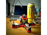
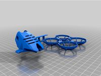
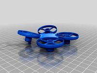
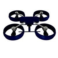
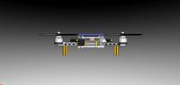
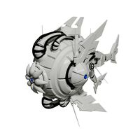
X-129R "Monster Whoop" - Micro Brushless 3D Printed FPV Quadcopter Drone Frame Kit by Karamvir_Bhagat
by Thingiverse
Last crawled date: 3 years ago
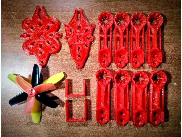
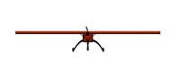
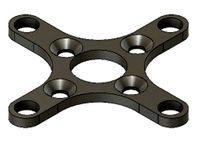
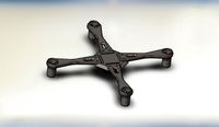
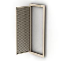
X-129R
Frame Specifications:
Frame: True X
Motor to motor: 129 mm
Motor mount configuration: 9 mm – 12 mm in M2 hardware
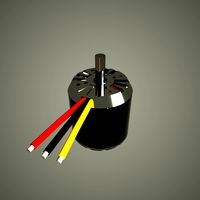
Recommended Motors: 11xx – 14xx
Propeller: Clearance for 3" propellers
Stack mounting:
X-129 & X-129 both accept 16 mm x 16 mm in M2
X-129 is for 20 x 20 up to M3. Adapters can be used for M2.5
X-129R is specifically for M2 in particular the Emax Magnum Mini F3 stack
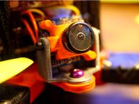
Camera Mounting:
19 x 19 cameras and Tiny Whoop Cameras up to 13.8 mm lens diameter with use of adapter piece.
File Designation & Selection - IMPORTANT:
Please kindly familiarize yourself with the build guide below for a full understanding.
For M2 hardware use only files labelled X-129R.
For hardware up to M3 use files labelled X-129
DO NOT MIX FILES FOR YOUR BUILDS. THEY ARE LABELLED SO THAT THEY WILL SELF ORDER IN YOUR FILE BROWSER FOR EASE OF SELECTION.
Facebook Group: https://www.facebook.com/groups/254825821981391/
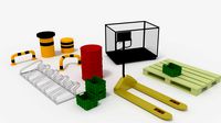
Build & Parts Guide:
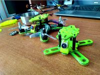
This quad like all other Monster Whoops is designed to be flexible and accommodating to allow you to utilize the maximum number of components with ease and to build in various configurations.
There is no “strict” build instruction. It is a case of understanding how the parts function together to allow you to build a quad.
This frame was intended to allow people to transfer their parts directly across a Babyhawk R. Therefore, all the hardware is in M2, save for the camera mount slot which is in M3.
I wanted the designed to be versatile so I created two versions. The X-129 and the X-129R. The X-129 is for M3 hardware and with adapters can utilizes M2 AND M2.5 hardware also. The X-129R is specifically for use with the BabyHawk R parts and is therefore only takes hardware in M2.
DO NOT MIX FILES IN YOUR BUILD THEY ARE LABELLED CLEARLY.
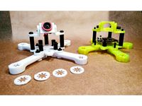
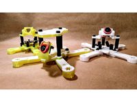
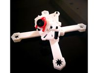
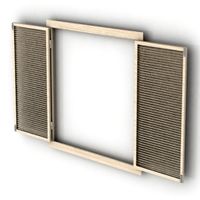
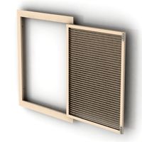
To build, mount 4 arms to the body plate by use of the adequate hardware. You will need to secure this via two points to lock in place. If you choose to keep your stack straight you will need to mount through into the bottom of the stack. If you wish to separate your stack for additional protection you can rotate it corner forward like a Tiny Whoop.
You can use a second body plate as a top plate and then mount arms off this to modify your configuration. Otherwise you can utilize the provided Top Plate to keep AUW to a minimum.
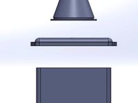
You will note that body, top plates and arm plates come in variety of thicknesses.
These are 2.8 mm, 1.7 mm and 1.1 mm.
This is to allow you to stack plates together to make up a single piece. This adds flexibility and shock resistance and also allows you to experiment with different colours and materials.
Recommend combinations are listed below:
Structural pieces:
You should use thicknesses of 2.8 mm or that equate to at least this. You should not exceed a maximum of 3.3 mm
Open Sandwich: For example, one 1.7 mm piece + one 1.1 mm piece.
Classic Sandwich: 1.1 x 3.
A TPU core flanked by PLA or PETG has been quite durable and makes a good combination and prevents tearing off of electronic components in hard impacts.
Hybrid:
There are three kinds of hybrids that you can make.
The first involves placing a 1.1 mm plate on top of 2.8 mm core structural piece or on top of a three-dimensional piece such as arm. In different colours and different piece combinations this can appear quite attractive.
The second is for added protection and vibration reduction. You can do the same as above and print in TPU. This will prevent parts from getting ripped off during very hard impacts and will additionally provide inherent dampening and “soft mounting” to motors and the flight stack.
The third is for anyone who wishes to utilize the plate files and have them cut in carbon. They can then utilize the printed parts as the wish to add decoration or strength.
Arms:
The arms come in “Plate” form in the same designation as above and also in a three-dimensional form. Of the latter there are 4 types.
Arm: This is the standard arm and is the heaviest but strongest of all the pieces. It is recommended for more powerful setups and 13xx + motors.
Arm Lite: This is the same as the standard arm but is slightly shorter in height and therefore also lighter. This is recommended for 11xx motors.
Arm Vertical: This is the same in dimension as the regular arm with the plate section cut away. This is to allow greater airflow and to reduce weight. This is recommended for use with 13xx + motors.
Arm Vertical Lite: This is the same as the Arm Vertical but is slightly shorter in height and therefore also lighter. This is recommended for 11xx motors.
Camera Mounting:
X-129 & X-129 will require M3 hardware to secure the camera mount to frame in the slot. The slot is to allow you to adjust your camera position to suit your liking.
The camera mounts have been given extra clearance at 20 mm so that 19 x 19 cameras can fit with ease. You will need M2 hardware to mount your camera.
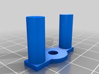
There 5 main camera mount pieces you can use.
The first is the main camera mount and it can be it is the tallest with holes on either side to mount the camera.
The second camera mount is the same as the first but has a slot to allow you to adjust your vertical camera position.
The “Drop Head” mount allows you to mount down off the Top Plate and again the same as the main mount in appearance but is a shorter mount with holes in M2.
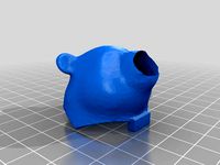
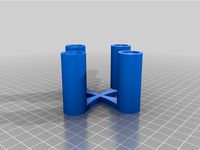
The Universal Camera Mount Adapter will accommodate lenses up to 13.8 mm in diameter. This is meant for Tiny Whoop style, de-cased or separated camera units. To mount your camera, begin by getting a small elastic/rubber band, looping it over the lens and putting one twist in it to look like an 8. Take the other loop, pull it up and over the back of your camera and hook it over the lens to secure. Be careful of your wires and your lens when installing to avoid any damage.
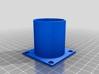
Soft Mounts & Shims:
Depending on the material that you use to print these, these can be either shims or soft mounts (or both). There are different thicknesses for you to choose from so that you can get the best fit for your motors.
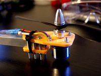
Motor Mounting:
YOU MUST USE AT LEAST 3 BOLTS FOR YOUR MOTORS! USING 2 BOLTS WILL CAUSE A MID AIR MOTOR DETACHMENT IF YOU ARE NOT CAREFUL!
Important Notes:
I have not been able to source parts from any companies to help me develop my frames.
I ensure to use the listed measurements and to check for fitment where I can with parts I have to hand. I try very hard to ensure that fitment is the best that I can achieve without physically having the parts to verify this. I have used my friend's Babyhawk R to test for fitment and it appears that there are no issues.
I must therefore state that since I have not personally tested this frame in flight, that it is a "beta" version. Once someone can kindly confirm by way of a flight DVR I will remove this label. I wanted to inform you the user so that at least you are aware of this before you invest any of your time or money.
Using and creating third party parts:
This frame was made like the other Monster Whoops frames to be easily customized and to accept additional parts easily. The standard hole mounts have been included in X and + configurations to allow for maximum versatility. These can be used for accessory mounting or allow antennas, wires or zip ties to pass through.
Since the holes are using the standard patterns it should be easy for you to make add on parts that fit easily to customise your build.
Tuning:
One concept I am exploring is how the proportions of the frame and its dimensions relative to each other can be used to naturally cancel out and inhibit/dampen inherent vibration.
I call this concept active geometry. It is based on the principles that form can tune vibration, for example in a pitch fork and that opposing kinetic vectors (vibrations) can cancel each other.
Every part of this frame is in perfect proportion and the dimensions are governed by a formula that I created. This is why the frames have their unique appearance.
I have noted that I have less inherent vibration in my frames, less “jello” and a minimal need to tune, if any, to get good performance.
The most prominent thing that I notice is that my frames seem to have a unique tone.
I normally just transfer my parts from frame to frame as I design. I didn’t notice this at first, but one day I was watching some line of sight footage of the same parts on a carbon frame and noticed a surprising difference. Since then I have tried to pay close attention and do indeed feel that there is a noticeable silencing/muffling effect.
It’s hard to describe, but I think once you notice it, it of stands out.
In the mid to high throttle range there seems to be less inherent jumpiness where you should normally expect to see it. It is in this throttle range where you also normally hear your quadcopter start to “scream”.
Somehow in my printed frame, the tone remains tight? I also note less twitchy response in general.
I would appreciate if anyone else could kindly pay attention to this and see if they too note can note this difference or anything in general when using this frame. I had made modifications to my frame mapping equation and want to see if this has any effect.
Flying advice:
Printed frames are not carbon frames, it’s easy to forget that when you are flying. It is advised to treat a printed frame like that of a Tiny Whoop and to avoid landing on the motor bottoms or corners of the arms.
When you first get it into the air, treat it gently until you get used to it. Since there frames are designed to balance perfectly and are actually “true X” this may feel a little strange at first. You may note that your sticks will be more even across all the axis of movement.
It is recommended to bottom mount the battery for the longevity of the frame and arms. Of course, once you are proficient and comfortable flying with the frame mount as you wish.
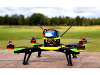
Plastic frames will protect your components very well, particularly from current and voltage spikes that normally kill components during crashes. Secondarily the frame breaking during an impact absorbs a great deal energy which would otherwise damage your components. The frames are designed to fully enclose the key components as much as possible of the drone so you should hopefully enjoy parts that last for a long time.
ALWAYS CHECK FLYING REGULATIONS AND RESTRICTIONS LOCAL TO YOU BEFORE ATTEMPTING TO FLY YOUR CRAFT.
Originality of Design
Of key importance to me is that my designs are original works. I always make my designs from scratch and try and make them as distinct as possible.
I have taken great care make sure that my design does not take directly from anyone else’s work or infringes on any copyrights or patents.
The unique geometry of this design alongside its unique design features identifies it as an original design and also builds in copy protection. If there is any duplication of any part of this design, a measurement can be taken of any two points and by simple calculation it can be proved.
I am a British citizen and this design was produced in the United Kingdom. The natural design rights reside with me as accorded by European Union law.
Just as a polite warning to anyone, I am legally trained.
Legal Disclaimer:
In no event shall I the designer be liable for any direct, indirect, punitive, incidental, special consequential damages, to property or life, whatsoever arising out of or connected with the use or misuse of any of my designs.
In using my work you acknowledge that any and all liability is with you the user.
You use this design at your own risk and are responsible for any consequences as such.
Frame Specifications:
Frame: True X
Motor to motor: 129 mm
Motor mount configuration: 9 mm – 12 mm in M2 hardware
Recommended Motors: 11xx – 14xx
Propeller: Clearance for 3" propellers
Stack mounting:
X-129 & X-129 both accept 16 mm x 16 mm in M2
X-129 is for 20 x 20 up to M3. Adapters can be used for M2.5
X-129R is specifically for M2 in particular the Emax Magnum Mini F3 stack
Camera Mounting:
19 x 19 cameras and Tiny Whoop Cameras up to 13.8 mm lens diameter with use of adapter piece.
File Designation & Selection - IMPORTANT:
Please kindly familiarize yourself with the build guide below for a full understanding.
For M2 hardware use only files labelled X-129R.
For hardware up to M3 use files labelled X-129
DO NOT MIX FILES FOR YOUR BUILDS. THEY ARE LABELLED SO THAT THEY WILL SELF ORDER IN YOUR FILE BROWSER FOR EASE OF SELECTION.
Facebook Group: https://www.facebook.com/groups/254825821981391/
Build & Parts Guide:
This quad like all other Monster Whoops is designed to be flexible and accommodating to allow you to utilize the maximum number of components with ease and to build in various configurations.
There is no “strict” build instruction. It is a case of understanding how the parts function together to allow you to build a quad.
This frame was intended to allow people to transfer their parts directly across a Babyhawk R. Therefore, all the hardware is in M2, save for the camera mount slot which is in M3.
I wanted the designed to be versatile so I created two versions. The X-129 and the X-129R. The X-129 is for M3 hardware and with adapters can utilizes M2 AND M2.5 hardware also. The X-129R is specifically for use with the BabyHawk R parts and is therefore only takes hardware in M2.
DO NOT MIX FILES IN YOUR BUILD THEY ARE LABELLED CLEARLY.
To build, mount 4 arms to the body plate by use of the adequate hardware. You will need to secure this via two points to lock in place. If you choose to keep your stack straight you will need to mount through into the bottom of the stack. If you wish to separate your stack for additional protection you can rotate it corner forward like a Tiny Whoop.
You can use a second body plate as a top plate and then mount arms off this to modify your configuration. Otherwise you can utilize the provided Top Plate to keep AUW to a minimum.
You will note that body, top plates and arm plates come in variety of thicknesses.
These are 2.8 mm, 1.7 mm and 1.1 mm.
This is to allow you to stack plates together to make up a single piece. This adds flexibility and shock resistance and also allows you to experiment with different colours and materials.
Recommend combinations are listed below:
Structural pieces:
You should use thicknesses of 2.8 mm or that equate to at least this. You should not exceed a maximum of 3.3 mm
Open Sandwich: For example, one 1.7 mm piece + one 1.1 mm piece.
Classic Sandwich: 1.1 x 3.
A TPU core flanked by PLA or PETG has been quite durable and makes a good combination and prevents tearing off of electronic components in hard impacts.
Hybrid:
There are three kinds of hybrids that you can make.
The first involves placing a 1.1 mm plate on top of 2.8 mm core structural piece or on top of a three-dimensional piece such as arm. In different colours and different piece combinations this can appear quite attractive.
The second is for added protection and vibration reduction. You can do the same as above and print in TPU. This will prevent parts from getting ripped off during very hard impacts and will additionally provide inherent dampening and “soft mounting” to motors and the flight stack.
The third is for anyone who wishes to utilize the plate files and have them cut in carbon. They can then utilize the printed parts as the wish to add decoration or strength.
Arms:
The arms come in “Plate” form in the same designation as above and also in a three-dimensional form. Of the latter there are 4 types.
Arm: This is the standard arm and is the heaviest but strongest of all the pieces. It is recommended for more powerful setups and 13xx + motors.
Arm Lite: This is the same as the standard arm but is slightly shorter in height and therefore also lighter. This is recommended for 11xx motors.
Arm Vertical: This is the same in dimension as the regular arm with the plate section cut away. This is to allow greater airflow and to reduce weight. This is recommended for use with 13xx + motors.
Arm Vertical Lite: This is the same as the Arm Vertical but is slightly shorter in height and therefore also lighter. This is recommended for 11xx motors.
Camera Mounting:
X-129 & X-129 will require M3 hardware to secure the camera mount to frame in the slot. The slot is to allow you to adjust your camera position to suit your liking.
The camera mounts have been given extra clearance at 20 mm so that 19 x 19 cameras can fit with ease. You will need M2 hardware to mount your camera.
There 5 main camera mount pieces you can use.
The first is the main camera mount and it can be it is the tallest with holes on either side to mount the camera.
The second camera mount is the same as the first but has a slot to allow you to adjust your vertical camera position.
The “Drop Head” mount allows you to mount down off the Top Plate and again the same as the main mount in appearance but is a shorter mount with holes in M2.
The Universal Camera Mount Adapter will accommodate lenses up to 13.8 mm in diameter. This is meant for Tiny Whoop style, de-cased or separated camera units. To mount your camera, begin by getting a small elastic/rubber band, looping it over the lens and putting one twist in it to look like an 8. Take the other loop, pull it up and over the back of your camera and hook it over the lens to secure. Be careful of your wires and your lens when installing to avoid any damage.
Soft Mounts & Shims:
Depending on the material that you use to print these, these can be either shims or soft mounts (or both). There are different thicknesses for you to choose from so that you can get the best fit for your motors.
Motor Mounting:
YOU MUST USE AT LEAST 3 BOLTS FOR YOUR MOTORS! USING 2 BOLTS WILL CAUSE A MID AIR MOTOR DETACHMENT IF YOU ARE NOT CAREFUL!
Important Notes:
I have not been able to source parts from any companies to help me develop my frames.
I ensure to use the listed measurements and to check for fitment where I can with parts I have to hand. I try very hard to ensure that fitment is the best that I can achieve without physically having the parts to verify this. I have used my friend's Babyhawk R to test for fitment and it appears that there are no issues.
I must therefore state that since I have not personally tested this frame in flight, that it is a "beta" version. Once someone can kindly confirm by way of a flight DVR I will remove this label. I wanted to inform you the user so that at least you are aware of this before you invest any of your time or money.
Using and creating third party parts:
This frame was made like the other Monster Whoops frames to be easily customized and to accept additional parts easily. The standard hole mounts have been included in X and + configurations to allow for maximum versatility. These can be used for accessory mounting or allow antennas, wires or zip ties to pass through.
Since the holes are using the standard patterns it should be easy for you to make add on parts that fit easily to customise your build.
Tuning:
One concept I am exploring is how the proportions of the frame and its dimensions relative to each other can be used to naturally cancel out and inhibit/dampen inherent vibration.
I call this concept active geometry. It is based on the principles that form can tune vibration, for example in a pitch fork and that opposing kinetic vectors (vibrations) can cancel each other.
Every part of this frame is in perfect proportion and the dimensions are governed by a formula that I created. This is why the frames have their unique appearance.
I have noted that I have less inherent vibration in my frames, less “jello” and a minimal need to tune, if any, to get good performance.
The most prominent thing that I notice is that my frames seem to have a unique tone.
I normally just transfer my parts from frame to frame as I design. I didn’t notice this at first, but one day I was watching some line of sight footage of the same parts on a carbon frame and noticed a surprising difference. Since then I have tried to pay close attention and do indeed feel that there is a noticeable silencing/muffling effect.
It’s hard to describe, but I think once you notice it, it of stands out.
In the mid to high throttle range there seems to be less inherent jumpiness where you should normally expect to see it. It is in this throttle range where you also normally hear your quadcopter start to “scream”.
Somehow in my printed frame, the tone remains tight? I also note less twitchy response in general.
I would appreciate if anyone else could kindly pay attention to this and see if they too note can note this difference or anything in general when using this frame. I had made modifications to my frame mapping equation and want to see if this has any effect.
Flying advice:
Printed frames are not carbon frames, it’s easy to forget that when you are flying. It is advised to treat a printed frame like that of a Tiny Whoop and to avoid landing on the motor bottoms or corners of the arms.
When you first get it into the air, treat it gently until you get used to it. Since there frames are designed to balance perfectly and are actually “true X” this may feel a little strange at first. You may note that your sticks will be more even across all the axis of movement.
It is recommended to bottom mount the battery for the longevity of the frame and arms. Of course, once you are proficient and comfortable flying with the frame mount as you wish.
Plastic frames will protect your components very well, particularly from current and voltage spikes that normally kill components during crashes. Secondarily the frame breaking during an impact absorbs a great deal energy which would otherwise damage your components. The frames are designed to fully enclose the key components as much as possible of the drone so you should hopefully enjoy parts that last for a long time.
ALWAYS CHECK FLYING REGULATIONS AND RESTRICTIONS LOCAL TO YOU BEFORE ATTEMPTING TO FLY YOUR CRAFT.
Originality of Design
Of key importance to me is that my designs are original works. I always make my designs from scratch and try and make them as distinct as possible.
I have taken great care make sure that my design does not take directly from anyone else’s work or infringes on any copyrights or patents.
The unique geometry of this design alongside its unique design features identifies it as an original design and also builds in copy protection. If there is any duplication of any part of this design, a measurement can be taken of any two points and by simple calculation it can be proved.
I am a British citizen and this design was produced in the United Kingdom. The natural design rights reside with me as accorded by European Union law.
Just as a polite warning to anyone, I am legally trained.
Legal Disclaimer:
In no event shall I the designer be liable for any direct, indirect, punitive, incidental, special consequential damages, to property or life, whatsoever arising out of or connected with the use or misuse of any of my designs.
In using my work you acknowledge that any and all liability is with you the user.
You use this design at your own risk and are responsible for any consequences as such.
Similar models
thingiverse
free
X-814 Singularity Master Monster Whoop by Karamvir_Bhagat
... builds.
fully enclosed stack.
height adjustable 19 x 19 camera compatible with 1 mm clearance added.
beast mode built in.
thingiverse
free
X-82 "Monster Whoop" - 1.9 - 2.5 Inch Micro Brushless FPV Racing Drone Quadcopter by Karamvir_Bhagat
...y and all liability is with you the user.
you use this design at your own risk and are responsible for any consequences as such.
thingiverse
free
X-120 - 2 Inch "Monster Whoop" Micro Brushless Racing Drone Quadcopter by Karamvir_Bhagat
...just quickly and easily sketch something up for yourself. similary, if you want to have holes instead of slots...
thingiverse
free
M2 & M2.5 to M3 Adapters & Soft Mounts (20 x 20 mm Flight Controllers) by Karamvir_Bhagat
... rotate and mount the stack like a tiny whoop with a corner facing forward to in the regular manner by mounting through the arms.
thingiverse
free

Joza TX130 quadcopter frame
...are to be threaded m2.
i have had the plates cut out of 3mm carbon fiber plates. 1,5mm for the top plate. stand offs are printed.
thingiverse
free
XC-120 Patriot - Micro Brushless 2.5 inch "Monster Whoop" 3D Printable Quadcopter Drone by Karamvir_Bhagat
...just quickly and easily sketch something up for yourself. similary, if you want to have holes instead of slots...
thingiverse
free
X-107 - 2" Micro Brushless Drone Beta Testing by Karamvir_Bhagat
...ers note:
thank you very much your interest and for your participation should you wish to engage in the project!
karamvir bhagat
thingiverse
free

SPDVL3 - 3" Super light and Durable Freestyle Frame by Flowr
...ck, motors
20x20mm stack / 16x16mm stack / aio whoop board 25.5x25.5mm
110x - 140x (4x m2 hole pattern) motors
3" propellers
thingiverse
free
Axel's modular 3D printed quadcopter (wooden arms) by Axbri
...the same as my other quadcopter design with carbon fibre motor arms. check it out here: https://www.thingiverse.com/thing:2427724
thingiverse
free

"Monster Whoop" 19 x 19 & RunCam Camera Mount by Karamvir_Bhagat
...e long edge of the piece where the camera bolts in.
for the adapter print vertically with the lock points point up off the bed.
129R
thingiverse
free

ALEXANDER 129R GT3 by miketulen123
...alexander 129r gt3 by miketulen123
thingiverse
alexander 129r gt3
you are this car schel kleiner maken
thingiverse
free

Harness clamp for Brush Cutter by Arndmp3
...by arndmp3 thingiverse harness clamp for husqvarna brush cutters 129r or every bush cutter with tube 25,4mm replacement for...
thingiverse
free
X-814 Singularity Master Monster Whoop by Karamvir_Bhagat
...rip all. micro monster powerhouse. follow basic guide in x-129r to build. same principals apply. quick specs: fully modular....
Karamvir
thingiverse
free
Runcam Micro Sparrow Holder for X-153 and other similar Frames by real_darKing
...the x-153 abd x-132, a 3d printable frame by karamvir bhagat https://www.thingiverse.com/thing:3079727https://www.thingiverse.com/thing:2956351 thank you! about the thing: i wanted...
thingiverse
free
X-107 - 2" Micro Brushless Drone Beta Testing by Karamvir_Bhagat
...ers note:
thank you very much your interest and for your participation should you wish to engage in the project!
karamvir bhagat
thingiverse
free
X-120 - 2 Inch "Monster Whoop" Micro Brushless Racing Drone Quadcopter by Karamvir_Bhagat
... you the user.
you use this design at your own risk and are responsible for any consequences as such.
with love - karamvir bhagat
thingiverse
free
XC-120 Patriot - Micro Brushless 2.5 inch "Monster Whoop" 3D Printable Quadcopter Drone by Karamvir_Bhagat
... you the user.
you use this design at your own risk and are responsible for any consequences as such.
with love - karamvir bhagat
Bhagat
3d_sky
$8

Roman shades of velvet
...fill your room and provide its originality and splendor bhagat ...
thingiverse
free
Runcam Micro Sparrow Holder for X-153 and other similar Frames by real_darKing
...x-153 abd x-132, a 3d printable frame by karamvir bhagat https://www.thingiverse.com/thing:3079727https://www.thingiverse.com/thing:2956351 thank you! about the thing: i wanted to...
thingiverse
free
X-107 - 2" Micro Brushless Drone Beta Testing by Karamvir_Bhagat
...ers note:
thank you very much your interest and for your participation should you wish to engage in the project!
karamvir bhagat
thingiverse
free
X-120 - 2 Inch "Monster Whoop" Micro Brushless Racing Drone Quadcopter by Karamvir_Bhagat
... you the user.
you use this design at your own risk and are responsible for any consequences as such.
with love - karamvir bhagat
thingiverse
free
XC-120 Patriot - Micro Brushless 2.5 inch "Monster Whoop" 3D Printable Quadcopter Drone by Karamvir_Bhagat
... you the user.
you use this design at your own risk and are responsible for any consequences as such.
with love - karamvir bhagat
cg_trader
$20
Bhagat Singh | 3D
...3d print, bhagat singh figurine. bhagat singh bust. bhagat singh stl bhagat singh bhagatsingh revolutionary indian art sculptures
grabcad
free

Logo SD Bhagat
...logo sd bhagat
grabcad
that is my logo, for my vehicle.
grabcad
free

SCREW JACK By Dipraj Bhagat
...
to remove tyre it needs to lift vehicle upwards this jack helps to lift the vehicle upwards and makes tyre removal process easy
3dwarehouse
free
bhautik bhagat fc
...bhautik bhagat fc
3dwarehouse
3dwarehouse
free

bhautik bhagat 2
...bhautik bhagat 2
3dwarehouse
Whoop
thingiverse
free
whoop by MichaelJFPV
...whoop by michaeljfpv
thingiverse
whoop
thingiverse
free
Tiny Whoop holder for 2 whoops by d2000
...tiny whoop holder for 2 whoops by d2000
thingiverse
tiny whoop holder for 2 whoop mini drones and battery
thingiverse
free
Whoop frame by Brassekongo
...whoop frame by brassekongo
thingiverse
a tiny whoop frame
thingiverse
free
Whoop frame by Brassekongo
...whoop frame by brassekongo
thingiverse
my first whoop frame.
thingiverse
free
WHOOPS 4
...
whoops is another
big cinewhoop as addon for hyperlite tooth fairy race frame 4"
first flight https://youtu.be/xm9afwiiass
thingiverse
free
Tiny Whoop 65mm by binaryfpv
...tiny whoop 65mm by binaryfpv
thingiverse
tiny whoop 65mm
thingiverse
free
V-Tail Whoop by Mystereon
...v-tail whoop by mystereon
thingiverse
v-tail whoop .. wip
thingiverse
free
Tiny Whoop Case by 3DRCStore
...tiny whoop case by 3drcstore
thingiverse
tiny whoop case for transport.
thingiverse
free
Tiny Whoop Calibration Base
...tiny whoop calibration base
thingiverse
a base usefull to calibrate your tiny whoop
thingiverse
free
Tiny Whoop Gate by Imozeb
...tiny whoop gate by imozeb
thingiverse
custom tiny whoop gate. requires hot glue for assembly.
Brushless
turbosquid
$4
Brushless motor
...r download as 3ds, dxf, obj, xsi, wrl, fbx, dwg, dae, and skp on turbosquid: 3d models for games, architecture, videos. (1366202)
3d_export
$10
wheel and motor for mars rover
...last project: a mars rover concept. complete wheel and brushless electrical motor designed to attach to an atv or...
3d_export
$100
the volt futuristic ev hypercar
...future ! some design aspects : this is in-wheel (brushless hub) motors vehicle, for each motor the core part...
3d_export
$20
si cantik cargo plane for humanity medicine kit
...used for the tailboom. the electronic components used are brushless motor os 1000kv which can produce thrust 3kgas a...
free3d
free
N6375 Brushless Motor
...n6375 brushless motor
free3d
n6375 brushless motor
thingiverse
free

Tyro 79 brushless key
...tyro 79 brushless key
thingiverse
tyro 79 brushless key
thingiverse
free
Propeller antirotation brushless lock
...propeller antirotation brushless lock
thingiverse
propeller antirotation brushless lock
thingiverse
free
Brushless motor holder by NukeCraft
...brushless motor holder by nukecraft
thingiverse
brushless motor holder for bl3650
thingiverse
free
Brushless motor mount by robotbuilders
...brushless motor mount by robotbuilders
thingiverse
replacement mount for brushless motor.
thingiverse
free
Brushless motor mount by TarsVH
...brushless motor mount by tarsvh
thingiverse
a mount for a 2830 size brushless motor
Quadcopter
3d_export
$5
quadcopter
...quadcopter
3dexport
futuristic quadcopter design.<br>original design davidflo 77
turbosquid
$19
quadcopter
...lty free 3d model quadcopter for download as max, ma, and obj on turbosquid: 3d models for games, architecture, videos. (1591426)
turbosquid
$25
QuadCopter
... available on turbo squid, the world's leading provider of digital 3d models for visualization, films, television, and games.
3d_export
$5

Quadcopter 3D Model
...quadcopter 3d model
3dexport
quadcopter studio shaders
quadcopter 3d model vortex333 93968 3dexport
3d_export
$5

Quadcopter 3D Model
...quadcopter 3d model
3dexport
quadcopter aircraft helicopter
quadcopter 3d model greatghost 94019 3dexport
3d_export
$18
passenger quadcopter
... a multicopter is an aircraft built according to a helicopter scheme, with three or more rotors. previews rendered with redshift.
turbosquid
$159
Quadcopter Animated.
... available on turbo squid, the world's leading provider of digital 3d models for visualization, films, television, and games.
turbosquid
$19
Drone Quadcopter
... available on turbo squid, the world's leading provider of digital 3d models for visualization, films, television, and games.
turbosquid
$12
Drone Quadcopter
... available on turbo squid, the world's leading provider of digital 3d models for visualization, films, television, and games.
3d_export
$29
Quadcopter
...
questions about the continuation of the collection or the model can be asked here:<br>https://www.artstation.com/evgen_beg
Fpv
turbosquid
$1

FPV VTX Antenna
...e 3d model fpv vtx antenna for download as obj, fbx, and stl on turbosquid: 3d models for games, architecture, videos. (1230317)
3d_export
$9

Fpv logo 3D Model
...onogram vehicle part of auto transport 3d model logo emblem detailed high quality badge
fpv logo 3d model rmodeler 59628 3dexport
3d_export
$8
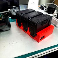
dji fpv battery slot holder
...er for 3 dji fpv batteries. holds perfectly without shaking. need 1 m3 countersunk head bolt. need to print 6 pin, 1 case, 1 cap.
3d_export
$10
fpv camera hd 700tvl
...aterials are logically named<br>the main format is in 3ds max 2009.<br>satisfcation garranteed..<br>thank you !
thingiverse
free
FpV Mount (SOPORTE FPV) by elborjas1987
...fpv mount (soporte fpv) by elborjas1987
thingiverse
this is a fpv mount with the same holes of naza base.
thingiverse
free
fpv by tbutera
...fpv by tbutera
thingiverse
fpv
thingiverse
free
fpv by tbutera
...fpv by tbutera
thingiverse
fpv
thingiverse
free
FPV DRONE ROOSTER DJI FPV PART
...fpv drone rooster dji fpv part
thingiverse
fpv drone rooster dji fpv install part
thingiverse
free
FPV monitor
...tml?rmmds=myorder&cur_warehouse=cn
link for download : https://cults3d.com/fr/mod%c3%a8le-3d/divers/fpv-monitor-ecran-fpv-faf
thingiverse
free
FPV receiver mount for FPV display by petrex
...eceiver mount for fpv display by petrex
thingiverse
aomway receiver mount for field view 777 fpv monitor. with small cable tray.
Drone
3d_export
$12
Drones
...drones
3dexport
drones
3d_export
$5
drone
...drone
3dexport
drone
3d_export
$6
drone
...drone
3dexport
high poly model of dji phantom 4 (drone)
3d_export
$5

drone
...drone
3dexport
drone military flight, sizes are in mm, modeled in fision 360
3d_export
free
drone
...drone
3dexport
drone de uso tactico, creado en blender version 2.79
3d_export
$35
DRONE
...drone
3dexport
turkey drone alpagu kamikaze foldable wing 3ds max 2019,2020,2021,2022 vray 5.00 rendered
3d_ocean
$29

Drone
...drone camera drone electronics justtomas military parrot plane robot sci-fi spy toy vehicle
drone by justtomas .c4d r16 .obj .3ds
turbosquid
$6

Drone
...rone
turbosquid
royalty free 3d model drone for download as on turbosquid: 3d models for games, architecture, videos. (1347051)
turbosquid
free
Drone
...drone
turbosquid
free 3d model drone for download as blend on turbosquid: 3d models for games, architecture, videos. (1688993)
turbosquid
$69
Drone
...e
turbosquid
royalty free 3d model drone for download as max on turbosquid: 3d models for games, architecture, videos. (1232508)
Monster
3d_export
$5
monster
...monster
3dexport
very realistic monster
3d_export
free

monster
...monster
3dexport
bloody monster! (looks terrifying)
3d_ocean
$12
Monster
... this code “envatoguest2016” . visit our store high details 3d character model for small monster , useful for animations, movi...
3d_ocean
$15
Monster
...monster
3docean
android game ios java main model monster playdesign
polycount :1118 texture :1024×1024png
3d_ocean
$8
Monster Man
...monster man
3docean
giant monster
monster man software: 3ds max, mental ray.
turbosquid
$60

MONSTER
...turbosquid
royalty free 3d model monster for download as max on turbosquid: 3d models for games, architecture, videos. (1220728)
turbosquid
$60
Monster
...turbosquid
royalty free 3d model monster for download as fbx on turbosquid: 3d models for games, architecture, videos. (1320840)
turbosquid
$19

Monster
...turbosquid
royalty free 3d model monster for download as max on turbosquid: 3d models for games, architecture, videos. (1248452)
turbosquid
$15
Monster
...turbosquid
royalty free 3d model monster for download as ztl on turbosquid: 3d models for games, architecture, videos. (1417804)
turbosquid
$15
Monster
...turbosquid
royalty free 3d model monster for download as max on turbosquid: 3d models for games, architecture, videos. (1293042)
Micro
3ddd
$1

Micro
...micro
3ddd
автобус
turbosquid
$80

MICRO
...ty free 3d model micro for download as max, c4d, obj, and fbx on turbosquid: 3d models for games, architecture, videos. (1700743)
3ddd
$1

JBL Micro Wireless
... micro , колонка , плеер
jbl micro wireless
turbosquid
$10
Suppressor Micro
...quid
royalty free 3d model suppressor micro for download as on turbosquid: 3d models for games, architecture, videos. (1380433)
turbosquid
$20
Micro Meter
...osquid
royalty free 3d model micro meter for download as fbx on turbosquid: 3d models for games, architecture, videos. (1350448)
turbosquid
$7

NIghtstand Micro
...d
royalty free 3d model nightstand micro for download as max on turbosquid: 3d models for games, architecture, videos. (1248117)
3ddd
$1
Micro wind turbine
...micro wind turbine
3ddd
турбина
micro wind turbine for your green building projects
turbosquid
$29
Micro Speakers
... available on turbo squid, the world's leading provider of digital 3d models for visualization, films, television, and games.
turbosquid
$29

Micro Servo.max
... available on turbo squid, the world's leading provider of digital 3d models for visualization, films, television, and games.
turbosquid
$20

Micro cells
... available on turbo squid, the world's leading provider of digital 3d models for visualization, films, television, and games.
Kit
turbosquid
$3

Bathroom Kit Baño kit
... available on turbo squid, the world's leading provider of digital 3d models for visualization, films, television, and games.
turbosquid
$19

Kit
... available on turbo squid, the world's leading provider of digital 3d models for visualization, films, television, and games.
3d_export
$20

Drift Kit
...drift kit
3dexport
turbosquid
$40

BitCoin Kit
...urbosquid
royalty free 3d model bitcoin kit for download as on turbosquid: 3d models for games, architecture, videos. (1519068)
turbosquid
$9
Industrial kit
...osquid
royalty free 3d model industrial kit for download as on turbosquid: 3d models for games, architecture, videos. (1144117)
turbosquid
$6

Kit Vases
...
turbosquid
royalty free 3d model kit vases for download as on turbosquid: 3d models for games, architecture, videos. (1285114)
turbosquid
free
Survival Kit
...rbosquid
royalty free 3d model survival kit for download as on turbosquid: 3d models for games, architecture, videos. (1637721)
turbosquid
$50
Ninja Kit
...rbosquid
royalty free 3d model ninja kit for download as fbx on turbosquid: 3d models for games, architecture, videos. (1672364)
turbosquid
$35
Brushes Kit
...osquid
royalty free 3d model brushes kit for download as max on turbosquid: 3d models for games, architecture, videos. (1216721)
turbosquid
$19
Medical kit
...osquid
royalty free 3d model medical kit for download as fbx on turbosquid: 3d models for games, architecture, videos. (1486089)
Frame
archibase_planet
free
Frame
...frame
archibase planet
frame photo frame
frame n190813 - 3d model (*.gsm+*.3ds) for interior 3d visualization.
archibase_planet
free
Frame
...frame
archibase planet
frame photo frame
frame n071113 - 3d model (*.gsm+*.3ds) for interior 3d visualization.
3ddd
$1

Frame
...frame
3ddd
frame
3ddd
free
Frame
...frame
3ddd
frame
archibase_planet
free

Frame
...frame
archibase planet
frame mirror frame ornament
frame n260113 - 3d model (*.gsm+*.3ds) for interior 3d visualization.
archibase_planet
free

Frame
...frame
archibase planet
frame photo frame
frame photo n190813 - 3d model (*.gsm+*.3ds) for interior 3d visualization.
archibase_planet
free
Frame
...frame
archibase planet
frame window window frame
frame 1 - 3d model (*.gsm+*.3ds) for interior 3d visualization.
archibase_planet
free
Frame
...frame
archibase planet
frame window frame window
frame 3 - 3d model (*.gsm+*.3ds) for interior 3d visualization.
archibase_planet
free
Frame
...frame
archibase planet
frame wall frame decoration
frame 1 - 3d model (*.gsm+*.3ds) for interior 3d visualization.
archibase_planet
free
Frame
...frame
archibase planet
frame window window frame
frame 2 - 3d model (*.gsm+*.3ds) for interior 3d visualization.
Printed
design_connected
$27

...print
designconnected
moroso print computer generated 3d model. designed by wanders, marcel.
3ddd
free

Eichholtz Prints
...- eichholtz print central station i
13 - eichholtz print central station ii
14 - eichholtz print marisa
15 - eichholtz print tish
3ddd
$1

Eichholtz Prints
...print abstract - set of 2
10 - eichholtz print orange abstract
11 - eichholtz print buddha right
12 - eichholtz print buddha left
turbosquid
$1
... available on turbo squid, the world's leading provider of digital 3d models for visualization, films, television, and games.
3ddd
free

Eichholtz Prints
...of 4
2 - print dunbar 2 set of 4
3 - print guadeloupe 1 set of 4
4 - print guadeloupe 2 set of 4
5 - print giles
6 - print trett
3ddd
$1

Eichholtz Prints
...nt tutti frutti
3 - eichholtz prints watson - set of 2
4 - eichholtz prints antique nautilus - set of 2
5 - eichholtz print tiara
3d_export
$5
Monster for printing
...monster for printing
3dexport
monster 3d model printing
3ddd
free
printed rug
...printed rug
3ddd
ковер
very creative printed rug
3ddd
free
Eichholtz Prints
...иал: бумага
габариты (вхш): 72 x 62 см
описание: print sweetmeat - постер в деревянной раме.
3 - prints varsity set of 2
арти
3ddd
free
Art Print Posters
...art print posters
3ddd
прованс
art print posters by patrician prints