GrabCAD

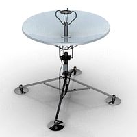
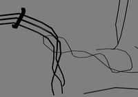
Wire Dipole Antenna with Adjustable "Open-Wire" Ladder Feed Line
by GrabCAD
Last crawled date: 2 years ago
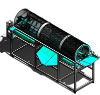
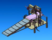
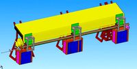
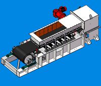
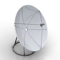
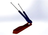
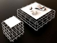
This is a model of a Half-Wavelength Wire Dipole Antenna with Adjustable "Open-Wire" Ladder Feed Line that is used to experiment with various wire feedline gaps that provide different feedline input impedances by changing the wire gap in 1/2 inch increments as shown in the table. The wire gauges are from #16 AWG (0.051" / 1.25mm) thru #8 AWG (0.128" / 3.25mm) and may need to be glued in place once the antenna is fully tuned. (Silver plated stranded wire with a protective insulation is best as long as the exposed areas are tinned with solder.) Non-metallic cable ties are used to secure the 3D printed plates together with (3) holes in the top of the plates for non-metallic ropes to hoist and secure the antenna. Note : This type of feedline is only good from 0.5 MHz (600 meters) to 50 MHz (6 meters).
The adjustment of the feedline impedance is NOT linear since the impedance is affected by the square of the radial distance between the wires. Coarse adjustment will happen as the wires get closer, and will have finer impedance changes as the wires are separated. Changing to thicker wire gauges (smaller #numbers) will lower the impedance roughly ~ 28 ohms. The most significant change is the resistance of the wire, but also wire diameter affects the wire-to-wire capacitance as larger wires will have smaller resistance but yet larger capacitance, so there will be a frequency shift and a necessary adjustment in inductive length for a specific center frequency. Again capacitance is dependent on the square of the radial distance between the wires, so widely spaced wires will lower the capacitance.
Optimal conditions are low resistance to high reactance = high Q which also determines the useable bandwidth for operation and reception. So tuning for bandwidth is probably a important first step. Next high impedance will lower current and maximize voltage for the electro-static field, but high currents will generate a higher magnetic field. Inductance is typically maximized for straight line wires and capacitance is typically used to center tune the frequency, but inductance length is limited to the wavelength and is typically shorter due to the velocity of propagation = velocity factor.
Note that from the magnetic field moments that the antenna feedline is directly inside the NEAR-FIELD radiation pattern and for this reason a differential pair wire transmission feedline is best since the effects on the feedline will be cancelled !! This is NOT true for coaxial cables and there will be currents on the outside of the coax that will cause undesired EMC/EMI/RFI radiation problems as well as VSWR and other antenna tuning problems, not to mention radiation power losses.
What is not shown in the model is the BalUn to coax/antenna tuner that would be the next connection typically close to the ground level (but not at - with at least a BalUn transition at least a foot above Earth ground). This is where the coax will attach or preferably (if possible) to the alUn to coax/antenna tuner that is very close to the transmitter/receiver; but it could also be outside a widow making sure that the entire length of the open wire feed line is a few feet away from metallic objects.
The problem with a ladder line is that it is VERY SENSITIVE to other metallic objects, so very careful considerations must be made just as if the feedline was the antenna ! So careful understanding of any nearby metallic objects is important (power lines, telephone lines, gutters, metal roofs, other antennas, ...etc) : https://www.rfcafe.com/references/electronics-world/loss-figures-300-ohm-twin-lead-january-1965-electronics-world.htm
The use of this experimenter is best explored in RECEIVING mode only; NOT in any transmitting modes and can be explored with a simple antenna tuner, antenna analyzer, or Vector Network Analyzer (VNA).
SAFETY NOTES : Antennas of this type can handle 10's of thousands of Volts and hundreds of Amps of current when used with high power transmitters typical in the Amateur Radio (Ham) bands. Therefore NEVER tune an antenna when it is live ! ! ! - - - Also DO NOT stand in the radiation pattern (NEAR FIELD) when it is operating either as there may be serious health effects. A good rule of thumb is to stay away at least a 1/4 wavelength (typically the distance the antenna is raised in height above Earth Ground) when it is operating. Also stay away from the mid-point of the antenna which is directly under the feed line when it is operating.
UPDATE (10/3/2021) : There is a good section in the ARRL's 'Antenna Physics' book that describes the experimentation of open wire transmission lines using a free simulation program called EZNEC that can warn and optimize wire length and wire spacing based upon frequency, wire diameter, and insulation types. I recommend using this as part of the experimentation to help achieve optimal results. Additional source material is in chapter 23 of the ARRL 'Antenna Book' as well.
UPDATE (1/6/2022) : Hollowing out (cone drill) the tuning plates where at all the wire entry and exits out will break sharp edges that will cause the wire to kink and break over time from wind vibrations. Also it is recommended to keep the wires taut to restrict the vibrational motion of the antenna under wind gusts, which will shift the wires back and forth creating stress fractures in the wire, even with stranded wire. Adding some silicon adhesive at each of the cone wire entry and cone wire exit points will create a soft grommet to reduce the stress of fracturing the wire.
Similar models
grabcad
free

Wire Dipole Antenna with Adjustable Transmission Line Impedance "Open-Wire" Ladder Feed Line
...air wire transmission feedline is best since the effects on the feedline will be cancelled !! this is not true for coaxial cab...
grabcad
free

Wire Dipole Antenna with Adjustable Ladder Feed Line
...hen it is operating. also stay away from the mid-point of the antenna which is directly under the feed line when it is operating.
grabcad
free

Wire Dipole Antenna Ceramic Egg Insulator
...nna classics - volume 3"; all of which are excellent references for learning and building wire high frequency (hf) antennas.
grabcad
free

Orthoginal Dual BiQuad (omnidirectional) 2.4 GHz Antenna
... a balanced feed line at least 1/4 wavelength away from where the coax connector transitions. - see my other model as an example.
grabcad
free

450 Ohm Impedance Ladder Line Antenna Cable
...ine away from metal objects.
this type of wire is also affected by earth ground and should not be run close or along the ground.
grabcad
free

450 Ohm Impedance Ladder Line Antenna Cable
...k to the manufacturer is here and they also sell wire dipole cable supports too ! :
https://www.wimo.com/en/parallel-wire-450-ohm
3dwarehouse
free

Aircraft Communication Antenna
...raft #antenna #bent #broadcast #c70 #comm #dm #electrical #frequency #impedance #mhz #plane #polarization #radiation #radio #vswr
thingiverse
free

Build your own 900MhZ antenna. by FPV_Pilot
...esired frequency, than antenna is no good.
stl file.. print two of them with opening facing down. no supports needed.
good luck!
thingiverse
free

Inductive proxiity sensor by Harshwardhan
...type using electromagnetic induction, the magnetic type using a magnet, and the capacitance type using the change in capacitance.
grabcad
free

2m Amateur Radio Cycloid Omni-Directional Antenna
...wire feed from a balun lower down the mast similar to the feed method that i used in the...
Dipole
3d_export
$12

Indoor TV Antenna 3D Model
...signals uhf vhf band indoor radio mast telecommunication digital dipole doublet rabbit ears bipole indoor tv antenna 3d model...
thingiverse
free

Dipole Bracket for wire dipoles by PD5DJ
...e bracket for wire dipoles by pd5dj
thingiverse
wire dipole bracket for 300ohm and 450ohm twinlead..
screws needed are m4 type..
thingiverse
free

Dipol insulator light
...dipol insulator light thingiverse light verion of dipole ...
thingiverse
free

Dipole Insulator by richtma
...dipole insulator by richtma
thingiverse
two variations of a simple dipole insulator.
thingiverse
free

dipole holder by flegi
...dipole holder by flegi
thingiverse
dipole holder for boom 15x15mm and 6mm element
thingiverse
free

Gypsy Dipole Support by EB5TC
...gypsy dipole support by eb5tc
thingiverse
soporte para gypsy dipole.
gypsy dipole support.
thingiverse
free

Dipole holder by Mikx
...dipole holder by mikx
thingiverse
dipole holder for rg 316 and 1mm copper cable.
( with rafts for printing in abs )
thingiverse
free

433MHz dipole antenna by Tamadite
...433mhz dipole antenna by tamadite
thingiverse
433mhz dipole antenna
thingiverse
free

Dipole Antenna Support by Amigache
...dipole antenna support by amigache
thingiverse
it is simply a support for dipole antenna, useful
thingiverse
free

Dipole Antenna Isolator by matrhint
...dipole antenna isolator by matrhint
thingiverse
this is a quick and simple part for putting up a dipole antenna.
Ladder
archibase_planet
free

Ladder
...ladder
archibase planet
step-ladder steps pair of steps
rung ladder n310707 - 3d model for interior 3d visualization.
3ddd
$1

Ladder
...ladder
3ddd
лестница , стеллаж
scano classic-ladder-565x1672x980
archibase_planet
free

Ladder
...ladder
archibase planet
step-ladder steps pair of steps
ladder n220610 - 3d model (*.gsm+*.3ds) for interior 3d visualization.
3ddd
$1

Лестница, ladder
...лестница, ladder
3ddd
ladder
лестница, ladder
turbosquid
free

Ladder
...ladder
turbosquid
free 3d model ladder for download as dae on turbosquid: 3d models for games, architecture, videos. (1189224)
3d_export
$50

ladder firetruck
...ladder firetruck
3dexport
ladder firetruck<br>an obj version of the ladder fire truck.
3ddd
free

Sliding Ladder
...sliding ladder
3ddd
лестница
sliding ladder
3d_export
$5

Ladder
...ladder
3dexport
3d_export
free

ladder
...ladder
3dexport
turbosquid
$10

Ladder
...oyalty free 3d model ladder for download as lwo, obj, and lxo on turbosquid: 3d models for games, architecture, videos. (1225500)
Feed
3d_export
$10
Feed chang
...feed chang
3dexport
turbosquid
$10
Feed-Pump
...lty free 3d model feed-pump for download as 3ds, obj, and c4d on turbosquid: 3d models for games, architecture, videos. (1456492)
3d_export
$10
Hydraulic in-feed out-feed support roller
...s at adjustable height, while machining such as cutting, drilling and etc. it is operated by hydraulic and modeled in nx siemens.
turbosquid
$5

Feeding Troughs and Buckets
...free 3d model feeding troughs and buckets for download as fbx on turbosquid: 3d models for games, architecture, videos. (1582798)
3d_export
$180

Boiler Feed Unit 3D Model
...boiler feed unit 3d model
3dexport
boiler feed unit
boiler feed unit 3d model briancrosdale 76895 3dexport
turbosquid
$6
Bird Feed House
... available on turbo squid, the world's leading provider of digital 3d models for visualization, films, television, and games.
3d_export
$7
Conveyor belt feeding punching machine
...conveyor belt feeding punching machine
3dexport
conveyor belt feeding punching machine
3d_export
$6
automatic feeding and pipe cutting machine
...automatic feeding and pipe cutting machine
3dexport
automatic feeding and pipe cutting machine
3d_export
$6
ore feeding equipment mining machinery
...ore feeding equipment mining machinery
3dexport
ore feeding equipment mining machinery
3d_export
$5

feed system
...omponent and the executive element constitute the mechanical transmission system, the detection element and the feedback circuit.
Antenna
archibase_planet
free
Antenna
...chibase planet
antenna aerial television antenna
antenna kathrein n090913 - 3d model (*.gsm+*.3ds) for exterior 3d visualization.
archibase_planet
free
Antenna
...antenna
archibase planet
satellite antenna
antenna 1 - 3d model (*.gsm+*.3ds) for exterior 3d visualization.
archibase_planet
free
Antenna
...antenna
archibase planet
equipment satellite antenna
antenna 2 - 3d model (*.gsm+*.3ds) for exterior 3d visualization.
archibase_planet
free
Antenna
...ntenna
archibase planet
satellite antenna equipment dish aerial
antenna 3 - 3d model (*.gsm+*.3ds) for exterior 3d visualization.
archibase_planet
free
Antenna
...antenna
archibase planet
satellite antenna dish dish aerial
antenna 4 - 3d model (*.gsm+*.3ds) for exterior 3d visualization.
archibase_planet
free
Antenna
...e planet
antenna dish dish aerial
antenna c-band satellite s180-g n210612 - 3d model (*.gsm+*.3ds) for exterior 3d visualization.
3d_export
$5
car antenna
...car antenna
3dexport
car antenna, antenna, car gadgets
turbosquid
$1

antenna
...rbosquid
royalty free 3d model antenna for download as blend on turbosquid: 3d models for games, architecture, videos. (1655786)
3d_export
free

Station with antenna
...station with antenna
3dexport
station with antenna
turbosquid
$5
Antenna
...id
royalty free 3d model antenna for download as max and fbx on turbosquid: 3d models for games, architecture, videos. (1381532)
Wire
design_connected
$11

Wired
...wired
designconnected
wired computer generated 3d model.
design_connected
$11
Wires
...wires
designconnected
wires computer generated 3d model.
design_connected
$11
Wire
...wire
designconnected
ronda design wire computer generated 3d model. designed by roccadadria, luca.
3d_export
$5
wire
...wire
3dexport
wire 180x180 cm arhive rar 3dmax2019. obj. fbx. mat corona
turbosquid
$2
HDMI wire
... 3d model hdmi wire for download as wire, wire, fbx, and wire on turbosquid: 3d models for games, architecture, videos. (1644937)
turbosquid
free
wires
...bosquid
free 3d model wires for download as ma, obj, and fbx on turbosquid: 3d models for games, architecture, videos. (1214233)
3ddd
$1

Wire chair
...wire chair
3ddd
wire chair
turbosquid
$10
wires
... available on turbo squid, the world's leading provider of digital 3d models for visualization, films, television, and games.
turbosquid
$2

Wire
... available on turbo squid, the world's leading provider of digital 3d models for visualization, films, television, and games.
3d_export
$10

wire stripper
...wire stripper
3dexport
wire stripper 5 in 1
Line
design_connected
$20

Line
...line
designconnected
adriani e rossi line computer generated 3d model.
3ddd
$1

Line Credenza
...line credenza
3ddd
line credenza , комод
line credenza, small
designed by nathan yong
3d_export
$20

cheese line
...cheese line
3dexport
cheese line
3ddd
$1

Resta line
...resta line
3ddd
resta line
стул
3d_export
$15

elevator lining
...elevator lining
3dexport
elevator lining with carved elements and gold.
3ddd
$1

Resta line
...resta line
3ddd
resta line , барный
барный стул
3ddd
$1

Bubble line
...bubble line
3ddd
панель
гипсовые, стеновые 3д панели - bubble line
turbosquid
$25
Straight Line BearBrick Straight Line BearBrick
...ck straight line bearbrick for download as 3ds, max, and fbx on turbosquid: 3d models for games, architecture, videos. (1340992)
3ddd
$1

Line roset | Fenge
...3ddd
fenge , line roset , кожа
диван line roset
design_connected
$11

Framed Line
...framed line
designconnected
jacco maris framed line computer generated 3d model. designed by maris , jacco.
Adjustable
3d_ocean
$7

Adjustable Wrench
...adjustable wrench
3docean
adjustable wrench highly detailed wrench
highly detailed adjustable wrench.
3ddd
$1
Adjustable Stool
...adjustable stool
3ddd
табурет
wooden adjustable stool.
3d_ocean
$20

Adjustable Gym Bench
...st adjustable bench black equipement gym gymnastic indoor silver sport workout
3d model of black and silver adjustable gym bench.
3d_ocean
$20
Adjustable Gym Bench
...st adjustable bench black equipement gym gymnastic indoor silver sport workout
3d model of black and silver adjustable gym bench.
3d_ocean
$16

Adjustable Weight Bench
...arbell bench black equipement gym gymnastic indoor sport weight workout
3d model of black adjustable weight bench with a barbell.
turbosquid
$5

Adjustable wrench
...
royalty free 3d model adjustable wrench for download as fbx on turbosquid: 3d models for games, architecture, videos. (1313414)
3d_export
$5
adjustable tension lock
...adjustable tension lock
3dexport
adjustable tension lock
turbosquid
$1

Adjustable Wrench
...free 3d model adjustable wrench for download as obj and blend on turbosquid: 3d models for games, architecture, videos. (1446736)
turbosquid
$1

Adjustable Wrench
...y free 3d model adjustable wrench for download as c4d and fbx on turbosquid: 3d models for games, architecture, videos. (1379022)
3d_export
$5
Adjustable key
...adjustable key
3dexport
Open
3d_export
free
Opener
...r
3dexport
3d model of can opener. its my first work, if u can please show me my mistakes. this 3d model was created in autocad.
3d_export
free
Cap opener
...cap opener
3dexport
handy cap opener, more files/formats here:
3ddd
$1
Кресло, Open Oreon.
...кресло, open oreon.
3ddd
open , oreon
кресло, open oreon.
3d_ocean
$4
Open Book
...r interior max mental model open ray reading shelf text vray
open hardcover book with unique texture map on front and back cover.
turbosquid
$6
Opening Flag
...squid
royalty free 3d model opening flag for download as c4d on turbosquid: 3d models for games, architecture, videos. (1593555)
turbosquid
$10

Open book
...
royalty free 3d model open book for download as skp and obj on turbosquid: 3d models for games, architecture, videos. (1690781)
turbosquid
$2

bottle opener
...lty free 3d model bottle opener for download as blend and obj on turbosquid: 3d models for games, architecture, videos. (1621201)
turbosquid
$24

Bottle Opener
...free 3d model bottle opener for download as max, obj, and fbx on turbosquid: 3d models for games, architecture, videos. (1300948)
turbosquid
$20
Open Box
...yalty free 3d model open box for download as ma, obj, and fbx on turbosquid: 3d models for games, architecture, videos. (1481218)
turbosquid
$10
Wine Opener
...ty free 3d model wine opener for download as ma, obj, and fbx on turbosquid: 3d models for games, architecture, videos. (1240730)