Thingiverse
Widescreen Mil-Plastic CyberDeck by DavidIT
by Thingiverse
Last crawled date: 3 years, 3 months ago
This is my Remix of a really cool case by Back7 (https://back7.co/)
This remix does not contain all the parts needed to print this project, the missing parts can be downloaded from Back7's original post.
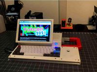
I wanted to use a 11.6, Widescreen panel I got out of a broken HP stream book (or what ever it was called.) The panel is called a "NT116WHM-N21" and both the driver and a off brand panel are available from eBay for less then $70 USD. I also made a few other changes that are listed below.
I printed mine in normal PLA at between 20% to 25% infill at speeds between 50 to 70. I originally printed most of the parts on my Ender's original build surface but it lost its magnet strength and curled up. This happened during a unrelated print and I didn't catch this in time and the head dug into my build surface. I replaced the build surface on both my Enders with glass + PEI. The bottom of my prints have now lost their textured surface and now have a glossy, mirror like surface. For projects like this in the future, I might buy a similar textured build surface.
List of changes:
-Extended the frame to accommodate a wider screen.
-Every part is printable on an Ender 3 (anything with a Build volume of 220x200)
-I added feet to the lower ribs to better angle the screen. (the screen is not IPS)
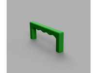
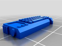
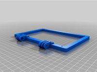
-Added a handle.
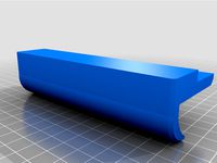
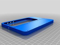
-Made a screen mounting system for my panel.
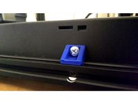
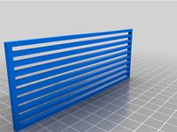
-Split the back panel (to be ender printable) and added the same cutouts that are featured on the sides. (you can find blank versions and versions that take less screw.)
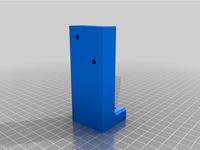
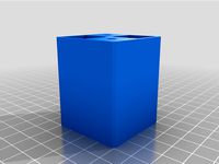
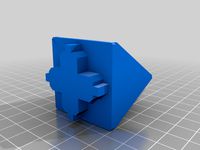
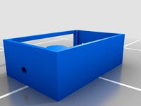
-made a two part Pi mount that slots into the larger cutouts. (can fit any one of the four or the two on the original design.)
-That's it for now, may add more in the future.
You'll need all the same hardware that the normal case uses (M5 25mm 25PK, M5 12mm 25PK, 4 M5 300mm threaded rod, and some similar looking M3 screws) and you'll also need a pack of M2.5 screws. You need a small assortment of them and you can buy packs of "250" on eBay in pan or hex head styles. Oh, and two 3mm dowels (I bought a pack of 3mm, 30mm long metal dowels off amazon.) See Back7's website for more information.
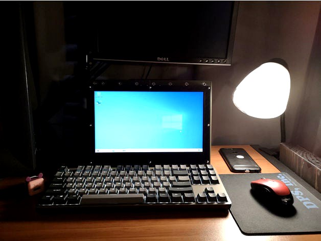
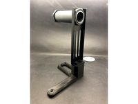
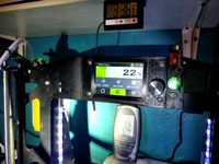
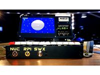
This is a work in progress and you can see in the photos that I'm using this as a monitor for now. I have a Pi 3 (non +) and I'm putting off upgrading until the Pi 5 or 4+ comes out.
I also have some other panels and mounts to finish. I have two versions of the Pi mount in the works (one for the skinny slot, the other is a revised version of the large panel mount) and other panels for speakers or cooling fans.
I also want to make, with caution, a mount for a SKR driver board (the ender 3 compatible one) that has all the appropriate connections mounted to the panel with D'Sub connectors and high current connectors. I think this will be useful for making, and then taking down, custom 3d printers I want to make. I want to make sure I have a good way to cool the board before releasing this mount.
I left the threaded rods uncut because I want to use them to bolt on addons or wire management frames that I will work on in the future. They currently stick out about 25mm.
If you have any suggestions or questions, just leave a comment! This is my first post and my phones camera (or my photo taking skills) suck. I might update the photos later if I get a better camera or find out how to take better photos.
BTW the extra M2.5 screw holes on the back panels are for mounting a, not yet exciting, clip or zip tie mount to allow you to separate the case down the middle to protect one half from the other (heat or electrical interference maybe) I don't think this will ever be needed but I wanted to leave the door open for it later.
How it fits together by addon:
--Screen--
To print:
You need to print 4 driver spacers, 4 frame spacers, two Tblocks, the two frames (B is the left side, A is the right) and the 2 face plates.
Hardware needed:
4 m5 screws (25mm) and quite a few m2.5 screws. There is a lot of extra room for longer screws so just use ones that don't poke through the plastic and into the screen.
How to put together:
Basically, bolt the Tblocks into the screen frames and then bold the whole screen frame to the main frame from behind. You need to use the spacers or the screws will stab the screen. After that, place the screen in and screw in the Face plates. The screen itself never gets screwed in anywhere. Its also easier to do this with most of the ribs and sides off.
--Handle--
To print:
4 upper ribs with dowel holes, 2 upper ribs with "handle gap" and the handle.
Hardware needed:
Two metal 3mm dowels that are bigger then 20mm but smaller then 40mm (I used 30mm) and no other special hardware.
How to put together:
You cant center the handle due to how some ribs get screwed in from the front and some don't.
You can put it together before screwing anything in by (This is starting left to right) inserting the dowel pin into the right side of the rib with the dowel hole, then sliding the upper rib with a gap onto that, then the handle and then another rib with a dowel hole (those ribs have holes on both sides) Then just do the same thing on the other side. The whole thing can be screwed in with 4 M5 screws like any other ribs.
You may need to cut away material from the holes to make the dowels fit. the hole on the handle is over sized already so that can be left alone.
The rest is pretty self explanatory.
This remix does not contain all the parts needed to print this project, the missing parts can be downloaded from Back7's original post.
I wanted to use a 11.6, Widescreen panel I got out of a broken HP stream book (or what ever it was called.) The panel is called a "NT116WHM-N21" and both the driver and a off brand panel are available from eBay for less then $70 USD. I also made a few other changes that are listed below.
I printed mine in normal PLA at between 20% to 25% infill at speeds between 50 to 70. I originally printed most of the parts on my Ender's original build surface but it lost its magnet strength and curled up. This happened during a unrelated print and I didn't catch this in time and the head dug into my build surface. I replaced the build surface on both my Enders with glass + PEI. The bottom of my prints have now lost their textured surface and now have a glossy, mirror like surface. For projects like this in the future, I might buy a similar textured build surface.
List of changes:
-Extended the frame to accommodate a wider screen.
-Every part is printable on an Ender 3 (anything with a Build volume of 220x200)
-I added feet to the lower ribs to better angle the screen. (the screen is not IPS)
-Added a handle.
-Made a screen mounting system for my panel.
-Split the back panel (to be ender printable) and added the same cutouts that are featured on the sides. (you can find blank versions and versions that take less screw.)
-made a two part Pi mount that slots into the larger cutouts. (can fit any one of the four or the two on the original design.)
-That's it for now, may add more in the future.
You'll need all the same hardware that the normal case uses (M5 25mm 25PK, M5 12mm 25PK, 4 M5 300mm threaded rod, and some similar looking M3 screws) and you'll also need a pack of M2.5 screws. You need a small assortment of them and you can buy packs of "250" on eBay in pan or hex head styles. Oh, and two 3mm dowels (I bought a pack of 3mm, 30mm long metal dowels off amazon.) See Back7's website for more information.
This is a work in progress and you can see in the photos that I'm using this as a monitor for now. I have a Pi 3 (non +) and I'm putting off upgrading until the Pi 5 or 4+ comes out.
I also have some other panels and mounts to finish. I have two versions of the Pi mount in the works (one for the skinny slot, the other is a revised version of the large panel mount) and other panels for speakers or cooling fans.
I also want to make, with caution, a mount for a SKR driver board (the ender 3 compatible one) that has all the appropriate connections mounted to the panel with D'Sub connectors and high current connectors. I think this will be useful for making, and then taking down, custom 3d printers I want to make. I want to make sure I have a good way to cool the board before releasing this mount.
I left the threaded rods uncut because I want to use them to bolt on addons or wire management frames that I will work on in the future. They currently stick out about 25mm.
If you have any suggestions or questions, just leave a comment! This is my first post and my phones camera (or my photo taking skills) suck. I might update the photos later if I get a better camera or find out how to take better photos.
BTW the extra M2.5 screw holes on the back panels are for mounting a, not yet exciting, clip or zip tie mount to allow you to separate the case down the middle to protect one half from the other (heat or electrical interference maybe) I don't think this will ever be needed but I wanted to leave the door open for it later.
How it fits together by addon:
--Screen--
To print:
You need to print 4 driver spacers, 4 frame spacers, two Tblocks, the two frames (B is the left side, A is the right) and the 2 face plates.
Hardware needed:
4 m5 screws (25mm) and quite a few m2.5 screws. There is a lot of extra room for longer screws so just use ones that don't poke through the plastic and into the screen.
How to put together:
Basically, bolt the Tblocks into the screen frames and then bold the whole screen frame to the main frame from behind. You need to use the spacers or the screws will stab the screen. After that, place the screen in and screw in the Face plates. The screen itself never gets screwed in anywhere. Its also easier to do this with most of the ribs and sides off.
--Handle--
To print:
4 upper ribs with dowel holes, 2 upper ribs with "handle gap" and the handle.
Hardware needed:
Two metal 3mm dowels that are bigger then 20mm but smaller then 40mm (I used 30mm) and no other special hardware.
How to put together:
You cant center the handle due to how some ribs get screwed in from the front and some don't.
You can put it together before screwing anything in by (This is starting left to right) inserting the dowel pin into the right side of the rib with the dowel hole, then sliding the upper rib with a gap onto that, then the handle and then another rib with a dowel hole (those ribs have holes on both sides) Then just do the same thing on the other side. The whole thing can be screwed in with 4 M5 screws like any other ribs.
You may need to cut away material from the holes to make the dowels fit. the hole on the handle is over sized already so that can be left alone.
The rest is pretty self explanatory.
Similar models
thingiverse
free
CR-6 Left Side Screen Mount and End Cap Cover by cghildreth
... and m5x8mm cap screws for the extrusion end-cap cover.
obviously, you'll have to re-route the screen cable to the left side.
thingiverse
free
FLSUN Q5 12864 Ender 3 Screen Mod by bsoderman2011
...print this mount with the screen facing the print bed and supports are only needed to support the 2 top mounts for the m4 screws.
thingiverse
free
Ender 5 Plus Voron M4 Extruder Mount by Apulo
...nuts to mount the runout sensor, 3 m5 screws and t-nuts to mount it to the frame, and 2 m5 screws and nuts to mount the extruder.
thingiverse
free
Spool Holder for Ender 3 uses factory holder by Djkirkendall
...ews that come with the ender 3. the holes are deep enough to accept the longer bottom frame screws.
print at 20% infill.
enjoy!
thingiverse
free
Handle with threaded holes by paulbernhardb
... it. use m5 screws to mount it somewhere.
i used it for the plexiglass door of my 3d printer enclosure.
prints without supports.
thingiverse
free
Screen Door Handle by flgoose
...his with extra wall thickness so you will have plenty material to drill and tap, the extra wall thickness also makes it stronger.
thingiverse
free
Ender 5 PSU mounts by smorris_12
...ront and side or all on the side and then dropped into the grooves in the lower rails.
printed in pla, 25% infill. raft optional.
thingiverse
free
Lerdge display frame for Prusa Steel clone
...anel, so part which i designed has a bezel with the 2 mm height on the back side. that's why supports is needed for printing.
thingiverse
free
Ender IDEX Screen Spacer, Ender 3 / Pro by Darkmyer
...hat attache the screen to the printer to attach the spacer to the extrusion then use two more to attach the screen to the scacer.
thingiverse
free
Ender 3 Vertical Screen Mount
...ce using m5 screws, and then the piece inserts to the end of the frame (must remove frame cap)
remixed from an ender 4040 end cap
Cyberdeck
3d_export
$15

cyberdeck
...;br>2k textures (pbr, metalic/roughness)<br>vertex count: 739<br>triangle count: 1,345<br>polygon count: 833
thingiverse
free
Cyberdeck by Chimerus
...cyberdeck by chimerus
thingiverse
28mm scaled shadowrun style cyberdeck, built for use in making stargrave hacker/codebreaker
thingiverse
free
Tommys cyberdeck by taaz
...deck i am trying to build.
update, so these are all scaled improperly, gonna have to wait and reupload this this once its fixed.
thingiverse
free
MSG Cyberdeck v2 by msglab
...t the msglab site:msglab.co/room/msg-cyberdeck-v2
thanks for checking this out and please reach out if you give the project a go!
thingiverse
free
Raspberry Pi HHKB Cyberdeck by ripxorip
...raspberry pi hhkb cyberdeck by ripxorip
thingiverse
7 inch cyberdeck design for raspberry pi and a hhkb keyboard.
thingiverse
free
Pinephone CyberDeck Case by 5ilver
...hone. the bottom area should be suitable to mount a keyboard in, and there is room on the side for a usb connection to the phone.
thingiverse
free
NX Yamato Cyberdeck by BlastoSupreme
...cally on a cr-10. you may wan to cut the big middle body part up in meshmixer. there will be more information added this weekend.
thingiverse
free
M3TAL Cyberdeck by BlastoSupreme
...u may have on twitter @blastosupreme or in the cyberdeck discord.
full writeup can be found at: https://cyberdeck.cafe/mix/m3tal
thingiverse
free

Virtuscope CyberDeck (For Mini Printer)
...ium-bodied-professional-plumbing-grade/dp/b00466v87s/). if you have any questions, feel free to find us on the cyberdeck discord.
thingiverse
free

Cyberdeck Plate for Raspberry Pi 400 by adafruit
...s for attaching extra breakout boards. this can be 3d printed, laser cut or cnc milled. heck, this could even be cut out of wood!
Widescreen
3d_ocean
$10
Widescreen Monitor
...is a 24 widescreen. inside the c4d file i labeled all objects parent and child. also there is a small info file included in th...
turbosquid
$19

Widescreen TV
... available on turbo squid, the world's leading provider of digital 3d models for visualization, films, television, and games.
3d_export
$45
Widescreen TV 3D Model
...
3dexport
tv television widescreen screen tube modern silver stand glass shelf
widescreen tv 3d model midnight oil 27868 3dexport
turbosquid
$65
TomTom widescreen Navigator
... available on turbo squid, the world's leading provider of digital 3d models for visualization, films, television, and games.
turbosquid
$20
acer_x193w widescreen tft
... available on turbo squid, the world's leading provider of digital 3d models for visualization, films, television, and games.
3d_export
$35
Widescreen LCD 19 3D Model
...
widescreen computer flatscreen screen display plasma monitor viewsonic wide lcd
widescreen lcd 19 3d model pairita 5334 3dexport
turbosquid
$40
Widescreen Plasma Television s2
... available on turbo squid, the world's leading provider of digital 3d models for visualization, films, television, and games.
3ddd
$1
Комод Artistica Ringo Widescreen Credenza
... ringo widescreen credenz
http://www.artisticahome.com/products/item_details.asp?item_no=282-420
turbosquid
$1
Widescreen Computer Monitor (16:9)
... available on turbo squid, the world's leading provider of digital 3d models for visualization, films, television, and games.
3d_export
free
Download free Philips WideScreen TV 3D Model
...2007 2008 2009 2010 2011 3ds interior model electronics electro computer
philips widescreen tv 3d model indesigner 22282 3dexport
Mil
3ddd
$1
mil
... mil , миль
выполненный в соответствии с каталогом ikea торшер из серии миль.
3d_ocean
$69

Mil-8T
...mil-8t
3docean
helicopter mil-8
3d model helicopter mil-8t render cocles polygons / triangles – 707 390 / 1 414 780
3ddd
$1
KRAUS, MIL-1200Х
...kraus, mil-1200х
3ddd
kraus , mil
cмеситель для ванных комнат из латуни kraus, mil-1200х
turbosquid
$199

Mil-24D Hind
...squid
royalty free 3d model mil-24d hind for download as max on turbosquid: 3d models for games, architecture, videos. (1188384)
turbosquid
$319

Mil Mi-35M
...ee 3d model mil mi-35m for download as 3ds, max, obj, and fbx on turbosquid: 3d models for games, architecture, videos. (1374646)
turbosquid
$79

Mil Mi-24
...d model mil mi-24 for download as 3ds, max, obj, fbx, and dae on turbosquid: 3d models for games, architecture, videos. (1169611)
turbosquid
$20
Mil OD Case
... available on turbo squid, the world's leading provider of digital 3d models for visualization, films, television, and games.
3d_export
$13
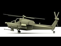
Mil Mi28 3D Model
...mil mi28 3d model
3dexport
mi-28 russian heli military
mil mi28 3d model alex121 33571 3dexport
3d_export
$50

food and drink-mil
...food and drink-mil
3dexport
best quality products<br>4k texture
turbosquid
$150

Mil-17 Pakistan Airforce
... available on turbo squid, the world's leading provider of digital 3d models for visualization, films, television, and games.
Plastic
archibase_planet
free

Plastic
...plastic
archibase planet
moulding friezes moldings border pilaster
deco plastic dw - 3d model for interior 3d visualization.
turbosquid
$1
Plastics
...
royalty free 3d model plastics for download as blend and fbx on turbosquid: 3d models for games, architecture, videos. (1581776)
archibase_planet
free

Plastic
...lastic
archibase planet
moulding friezes moldings border pilaster decor
deco plastic rz - 3d model for interior 3d visualization.
3ddd
$1
Plastic Playground
... kids , toy , child
plastic playground
3d_export
$5
plastic lid
...plastic lid
3dexport
plastic lid
3d_export
$5
plastic clothespin
...plastic clothespin
3dexport
plastic clothespin
turbosquid
$39

Plastics
... available on turbo squid, the world's leading provider of digital 3d models for visualization, films, television, and games.
3d_ocean
$3
Plastic Packaging
...ging plastic
intended for blender, cycles: plastic packaging to place your product in. subdivision modifier has not been applied.
3ddd
$1
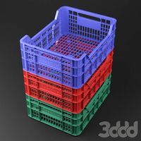
plastic box
... ящик
model of plastic box for fruits in 3 levels of detail. highpoly - 23,6k, midpoly - 7,3k and lowpoly - 2,6k polygons.
3d_ocean
$12
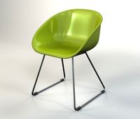
Plastic Chair
...furniture plastic chair side chair
3d model of plastic chair. 3ds and obj multi format files included. scanline renderer version.