Thingiverse
Wi-Fi Laundry Alarm by ReallyBigTeeth
by Thingiverse
Last crawled date: 3 years ago
If you like what you see here, consider leaving a tip.
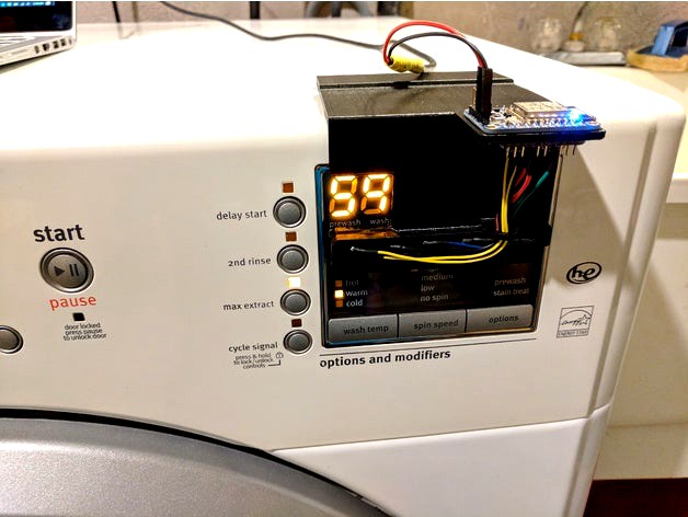
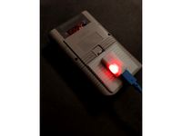
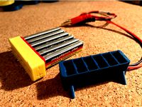
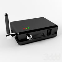
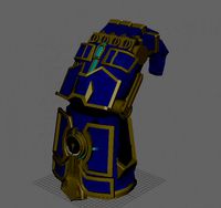
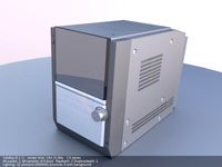
A Wi-Fi connected laundry alarm for Maytag 2000 series laundry machines. The device senses which front panel LED indicator light is turned on and displays the laundry's status on a local network page you can view in a web browser from a PC, smartphone, tablet, etc.
Updates:
2017 Nov 9
Fixed a coding error (funny spelling mistake in the HTML portion of the firmware).
2018 Jan 14
Added separate pages for washer and Dryer.
The machine cycle is now displayed in the window title or tab.
2018 Jan 15
Added simple linked index at address root.
Future Plans:
A Huzzah ESP8266 laundry alarm client with OLED display has been prototyped.
Bill of Materials:
Adafruit Huzzah esp8266 Wi-Fi breakout board ~ $13 CAD
6x Diodes ~ $6 - $12 CAD for pack of 100
6x 100kΩ resistors ~ $1 for pack of 10
6x Photoresistors ~ $5 for pack of 10
2x strong magnets (12mm diametre, 3 mm tall
Perfboard (for building the circuit)
~ 16 Gauge Wire & Shrink Tubing
Tools:
3D Printer
Computer with Arduino IDE (instructions for setup are below)
USB FTDI Cable (for programming the Wi-Fi breakout board)
Soldering Iron and Solder
Electronics Side Cutters
Sharp Knife
Wire Strippers
Sand Paper ~ 150 grit
Waxed Paper
Toothpick
Instructions:
First lets make sure you have a fully working Wi-Fi breakout board. It would be a shame to go to all the trouble of building the laundry alarm only to discover that the board was D.O.A..
Download and install the latest Arduino IDE for your computer's operating system. Next, get the Arduino IDE setup for the Huzza Wi-Fi board by following the Adafruit guide Here.
With the Arduino IDE working, open the source code file downloaded with the 3D printable frame "Laundry_Alarm_Huzzah_ESP8266.ino". You'll need to modify a few lines in that file to get the device connected to your Wi-Fi network. On line 41, you will need to enter your network's SSID between the double quotes. On line 42, enter your networks password between the double quotes. On line 43, give your Wi-Fi board a static ip address within your routers range. Take note that these have comma separated values eg. 192,168,1,100.
You do not need to enter your gateway and subnet. If you wish to use your router to assign a static ip, you can comment out line 43 and 161 by typing "//" without the quotes at the beginning of those lines. Now hit the upload button to program the Huzzah Wi-Fi board.
Use an electronics breadboard to build the circuit and make sure everything is working properly before going ahead with the rest of the build. (schematics can be found in the pictures at the top of the page, in the instructions below, and in the file downloads.
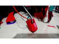
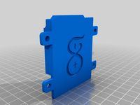
3D print the model and remove any adhesion material with a sharp knife. Sand any surface that will be in contact with your laundry machine and do any regular post processing to clean up the print. Place some wax paper on a flat, magnetically attractive surface. Rough the rear face and sides of the two magnets, mix some epoxy and glue the magnets in the frame. Place the frame magnet side down on the wax paper and place something heavy on top of the frame while the epoxy cures. This will ensure the magnets are flush with the outer surface of the frame, making a strong magnetic bond with your laundry machine while in use.
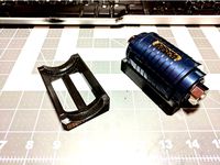
The microcontroller in the esp8266 Wi-Fi module has only one analogue input, so to take analogue readings from multiple sensors, a small circuit will have to be built which uses 6 digital pins to power each of the sensors. One by one, each sensor will be given power and an analogue reading will be taken. The highest value from those readings will be from the led on the laundry machine that was turned on, giving us the cycle in which the machine is currently engaged.
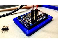
For testing, I used a wire wrap tool and wire jumpers to assemble the circuit leaving an ugly mess of wires. I originally used 10kΩ resistors which were too low a value for sensing the dim LEDs on my laundry machines. Switching to 100kΩ resistors resulted in much more stable light readings.
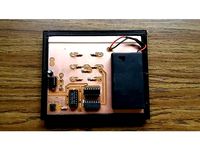
For the final build I put together a compact circuit board that fits under the Huzzah Wi-Fi board, serving the secondary purpose of securing the Wi-Fi board to the frame.
Start by drawing an outline of the circuit board, and use a sharp knife to cut a 3 x 6 solder pad grid as shown below.
Bend and trim the leads of the six diodes and and six resistors to for 3/10 inch spacing and lay out the components as below.
Solder the components in place.
Remove two to three millimetres of insulation from the end of six wires and splay the strands of each wire as pictured below. Tin the wires and solder each wire connecting each diode in line with its adjacent resistor.If you haven't already, make a solder bridge to attach the cathode ends of the diodes to the pad where the analogue pin of the Wi-Fi board will go, and another bridge from the resistors to the pad that the Ground pin will go.
Trim the board to size.
Set the circuit board aside for now. Insert the six photoresistors in the frame recesses. make sure they sit flush with the rear wall of the recesses.Mix enough two part epoxy to glue the photoresistors in place. Using a toothpick, pick up some epoxy and place a drop on either side of the photoresistors being careful not to get any on the face of the sensor.
Once the epoxy is cured, trim the photoresistor leads to about three millimetres length. Take the Huzzah Wi-Fi board and place it in the top of the frame.Take the circuit board you built earlier and fit it to the bottom of the Wi-Fi board sandwiching the frame between them, making sure the analogue and ground pins are in the right holes of the circuit board.
Solder both Ground Pins, pins 12, 13, 14, 15, 16, 4, and TX to secure the circuit board to the Wi-Fi board. Trim a short amount of insulation off of six wires and tin their ends. There is very little room to solder wires to the rear pins. Place the frame circuit board side up with the magnets pointing toward you. If you solder with your right hand, solder a wire to pin 13 first, then 12, 14, and finally 16. If you are left handed, solder the wires in the reverse order. solder the last two wires to pins 15 and 4. Now is a good time to place shrink tubing over all of the wires connected to the circuit board.
All that's left now is to trim the wires to length slip some shrink tubing on each wire and solder them to the photoresistors. Start with the wire from pin 16 and pair it with any wire between the diodes and resistors on the circuit board. It doesn't matter which one you chose as they all take the same electrical path to the ground and analogue pins. In the photo below, the photoresistor leads from left to right go to pins 12, 13, 14, 15, 16, and 4; 16 being directly below the loop that the wires go though. Bend the photoresistor leads for pin 16 toward the loop, trim the two wires to length, slip some heat shrink tubing over them and solder the wires to the leads, shrink the tubing, then do the same for photo resistors 4 and 15, then 14, 13, and finally 12.
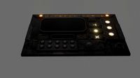
I'ts time to test it out. The board should magnetically connect to the metal surface at the top of the laundry machine aligning the six sensors with the laundry cycle LEDs on the front display. You can power the board with an FTDI cable and a USB power adapter, or you can cut the end off a spare USB cable and solder some female jumper wires to the ground and 5v wires of the USB cable. Connect the jumper wires to the ground and +5v pins of the FTDI header on the Huzza Wi-Fi board, and the other end of the USB cable to a power adapter and start a load of laundry.
Open a web browser on a computer connected to your home network. In the address field, type in the ip address of the Wi-Fi board and the machine you want to monitor separated by a forward slash (ex 192.168.1.100/washer or 192.168.1.100/dryer) to view the laundry machines current status. The page will automatically refresh every 60 sec to let you know what the machine is doing. Now you'll be alerted with a red/orange/blue flashing page the minute your laundry is done.
If you type "/rawWasher" or "/rawDryer" without the quotes after the ip address (ex
192.168.1.100/rawWasher), you will be shown the the current laundry cycle and the latest readings of all of the sensors refreshed every 5 seconds.
A Wi-Fi connected laundry alarm for Maytag 2000 series laundry machines. The device senses which front panel LED indicator light is turned on and displays the laundry's status on a local network page you can view in a web browser from a PC, smartphone, tablet, etc.
Updates:
2017 Nov 9
Fixed a coding error (funny spelling mistake in the HTML portion of the firmware).
2018 Jan 14
Added separate pages for washer and Dryer.
The machine cycle is now displayed in the window title or tab.
2018 Jan 15
Added simple linked index at address root.
Future Plans:
A Huzzah ESP8266 laundry alarm client with OLED display has been prototyped.
Bill of Materials:
Adafruit Huzzah esp8266 Wi-Fi breakout board ~ $13 CAD
6x Diodes ~ $6 - $12 CAD for pack of 100
6x 100kΩ resistors ~ $1 for pack of 10
6x Photoresistors ~ $5 for pack of 10
2x strong magnets (12mm diametre, 3 mm tall
Perfboard (for building the circuit)
~ 16 Gauge Wire & Shrink Tubing
Tools:
3D Printer
Computer with Arduino IDE (instructions for setup are below)
USB FTDI Cable (for programming the Wi-Fi breakout board)
Soldering Iron and Solder
Electronics Side Cutters
Sharp Knife
Wire Strippers
Sand Paper ~ 150 grit
Waxed Paper
Toothpick
Instructions:
First lets make sure you have a fully working Wi-Fi breakout board. It would be a shame to go to all the trouble of building the laundry alarm only to discover that the board was D.O.A..
Download and install the latest Arduino IDE for your computer's operating system. Next, get the Arduino IDE setup for the Huzza Wi-Fi board by following the Adafruit guide Here.
With the Arduino IDE working, open the source code file downloaded with the 3D printable frame "Laundry_Alarm_Huzzah_ESP8266.ino". You'll need to modify a few lines in that file to get the device connected to your Wi-Fi network. On line 41, you will need to enter your network's SSID between the double quotes. On line 42, enter your networks password between the double quotes. On line 43, give your Wi-Fi board a static ip address within your routers range. Take note that these have comma separated values eg. 192,168,1,100.
You do not need to enter your gateway and subnet. If you wish to use your router to assign a static ip, you can comment out line 43 and 161 by typing "//" without the quotes at the beginning of those lines. Now hit the upload button to program the Huzzah Wi-Fi board.
Use an electronics breadboard to build the circuit and make sure everything is working properly before going ahead with the rest of the build. (schematics can be found in the pictures at the top of the page, in the instructions below, and in the file downloads.
3D print the model and remove any adhesion material with a sharp knife. Sand any surface that will be in contact with your laundry machine and do any regular post processing to clean up the print. Place some wax paper on a flat, magnetically attractive surface. Rough the rear face and sides of the two magnets, mix some epoxy and glue the magnets in the frame. Place the frame magnet side down on the wax paper and place something heavy on top of the frame while the epoxy cures. This will ensure the magnets are flush with the outer surface of the frame, making a strong magnetic bond with your laundry machine while in use.
The microcontroller in the esp8266 Wi-Fi module has only one analogue input, so to take analogue readings from multiple sensors, a small circuit will have to be built which uses 6 digital pins to power each of the sensors. One by one, each sensor will be given power and an analogue reading will be taken. The highest value from those readings will be from the led on the laundry machine that was turned on, giving us the cycle in which the machine is currently engaged.
For testing, I used a wire wrap tool and wire jumpers to assemble the circuit leaving an ugly mess of wires. I originally used 10kΩ resistors which were too low a value for sensing the dim LEDs on my laundry machines. Switching to 100kΩ resistors resulted in much more stable light readings.
For the final build I put together a compact circuit board that fits under the Huzzah Wi-Fi board, serving the secondary purpose of securing the Wi-Fi board to the frame.
Start by drawing an outline of the circuit board, and use a sharp knife to cut a 3 x 6 solder pad grid as shown below.
Bend and trim the leads of the six diodes and and six resistors to for 3/10 inch spacing and lay out the components as below.
Solder the components in place.
Remove two to three millimetres of insulation from the end of six wires and splay the strands of each wire as pictured below. Tin the wires and solder each wire connecting each diode in line with its adjacent resistor.If you haven't already, make a solder bridge to attach the cathode ends of the diodes to the pad where the analogue pin of the Wi-Fi board will go, and another bridge from the resistors to the pad that the Ground pin will go.
Trim the board to size.
Set the circuit board aside for now. Insert the six photoresistors in the frame recesses. make sure they sit flush with the rear wall of the recesses.Mix enough two part epoxy to glue the photoresistors in place. Using a toothpick, pick up some epoxy and place a drop on either side of the photoresistors being careful not to get any on the face of the sensor.
Once the epoxy is cured, trim the photoresistor leads to about three millimetres length. Take the Huzzah Wi-Fi board and place it in the top of the frame.Take the circuit board you built earlier and fit it to the bottom of the Wi-Fi board sandwiching the frame between them, making sure the analogue and ground pins are in the right holes of the circuit board.
Solder both Ground Pins, pins 12, 13, 14, 15, 16, 4, and TX to secure the circuit board to the Wi-Fi board. Trim a short amount of insulation off of six wires and tin their ends. There is very little room to solder wires to the rear pins. Place the frame circuit board side up with the magnets pointing toward you. If you solder with your right hand, solder a wire to pin 13 first, then 12, 14, and finally 16. If you are left handed, solder the wires in the reverse order. solder the last two wires to pins 15 and 4. Now is a good time to place shrink tubing over all of the wires connected to the circuit board.
All that's left now is to trim the wires to length slip some shrink tubing on each wire and solder them to the photoresistors. Start with the wire from pin 16 and pair it with any wire between the diodes and resistors on the circuit board. It doesn't matter which one you chose as they all take the same electrical path to the ground and analogue pins. In the photo below, the photoresistor leads from left to right go to pins 12, 13, 14, 15, 16, and 4; 16 being directly below the loop that the wires go though. Bend the photoresistor leads for pin 16 toward the loop, trim the two wires to length, slip some heat shrink tubing over them and solder the wires to the leads, shrink the tubing, then do the same for photo resistors 4 and 15, then 14, 13, and finally 12.
I'ts time to test it out. The board should magnetically connect to the metal surface at the top of the laundry machine aligning the six sensors with the laundry cycle LEDs on the front display. You can power the board with an FTDI cable and a USB power adapter, or you can cut the end off a spare USB cable and solder some female jumper wires to the ground and 5v wires of the USB cable. Connect the jumper wires to the ground and +5v pins of the FTDI header on the Huzza Wi-Fi board, and the other end of the USB cable to a power adapter and start a load of laundry.
Open a web browser on a computer connected to your home network. In the address field, type in the ip address of the Wi-Fi board and the machine you want to monitor separated by a forward slash (ex 192.168.1.100/washer or 192.168.1.100/dryer) to view the laundry machines current status. The page will automatically refresh every 60 sec to let you know what the machine is doing. Now you'll be alerted with a red/orange/blue flashing page the minute your laundry is done.
If you type "/rawWasher" or "/rawDryer" without the quotes after the ip address (ex
192.168.1.100/rawWasher), you will be shown the the current laundry cycle and the latest readings of all of the sensors refreshed every 5 seconds.
Similar models
cg_trader
$3
Resistor - Through Hole with Solder
...to fit your project perfectly. the solder is independent from the resistors, so you can move it any apply it wherever you prefer.
3dwarehouse
free
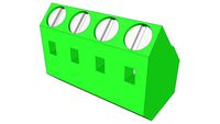
Terminal Block, circuit board, 4 wire
...rcuit board, 4 wire
3dwarehouse
4 wire terminal block to be soldered on circuit board #circuit #connector #electronics #terminal
thingiverse
free
Switch-Diode soldering station by Mangolicious
...he leg of the diode around a 1mm drill (0,04"), put in the switch (from the underside), put the diode in the pin and solder.
thingiverse
free
Retrofalg GPI Case - LiPo battery adapter (no mod version)
...protect your solders from short circuits (see pictures)
it was designed for type-c usb 5 v 1a 18650 tp4056 printed circuit board.
thingiverse
free
PCB Frame by jclymer01
...g your table tops and protecting your soldered joints. the stl is of one half of the frame. print two of them for a full frame.
thingiverse
free
PCB Box for diode circuit (used for inductive sensor) with lid. by drkztan
...iverse
i needed a place to put my little diode sensor pcb since i'm not a fan of soldering components in-line with my wires.
thingiverse
free
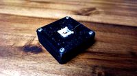
Huzzah ESP8266 Breakout Frame by baldengineer
...eakout board (https://www.adafruit.com/product/2471). just enough to get it off the workbench, but not impede access to the pins.
thingiverse
free
Tiny Whoop Parallel Charging Board by villekl
...ingiverse
parallel charging board for six tiny whoop batteries. requires pin headers to be soldered in place from the underside.
thingiverse
free
Dual 18650 and 20700 battery charger by japhillips87
...eans that if you want to fully use it's capability, use a 2 amp charger.
janm created a lid for the 18650 charger board here.
thingiverse
free
Arduino Leonardo Surface Mount Pouch by Kadrumir
...s of the controller that would also allow easy removal and insertion of the arduino for wiring.
use m4 screws to mount the thing.
Reallybigteeth
thingiverse
free

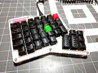
ALPS Macro Keycaps by ReallyBigTeeth
...y reallybigteeth
thingiverse
if you like what you see here, consider leaving a tip.
custome made alps keycaps for macro keyboard
thingiverse
free
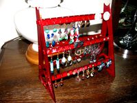
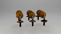
Earring/Jewellery Stand by ReallyBigTeeth
...he print bed. clip together to assemble. use a dab of glue if you wish.
thanks goes out to kyllikki for physical connections.
thingiverse
free
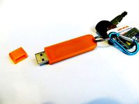
Corsair Voyager GT USB Case for Keyring by ReallyBigTeeth
...e what you see here, consider leaving a tip.
case for a corsair voyager gt usb stick that has a hole for attaching to a key ring.
thingiverse
free
Ergodox ALPS DCS Keycap set by ReallyBigTeeth
...eyboards with alps switches.
print right side up with support. sand the top surface for a more comfortable typing experience.
thingiverse
free
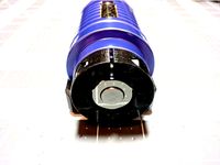
REVOMAZE Puzzle Grip by ReallyBigTeeth
...icator on the puzzle's core and tighten the screw.
the revomaze stand can be found here.
check out the revomaze website here.
thingiverse
free
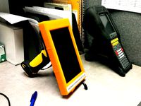
Nexus 7 (2013) Laser Barcode Scanner (Symbol LS3408) by ReallyBigTeeth
...erse
if you like what you see here, consider leaving a tip.
combine a nexus 7 (2013) with a symbol ls3408 laser barcode scanner.
thingiverse
free
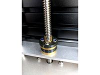
T8 Leadscrew Anti-Backlash Spacer by ReallyBigTeeth
.... the assembly is fastend together using m3 bolts. the model may need adjustment to get the correct thickness for your assembly.
thingiverse
free
REVOMAZE Stand - Remix by ReallyBigTeeth
...viewtopic.php?f=25&t=2430&p=55627#p55627
the revomaze puzzle grip can be found here.
check out the revomaze website here.
thingiverse
free
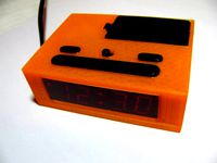
Digital Clock Case (Cardinal Model 6025 / 928) by ReallyBigTeeth
...al clock enclosure for cardinal alarm clock model 6025. basic model 928. uses battery door and buttons from original clock case.
thingiverse
free

Nexus 7 2013 Keyboard stand by ReallyBigTeeth
....
use a keyboard with your tablet while laying in bed, sitting in a chair, or at a desk.
assembly viideo
angle adjustment video
Wi
3ddd
$1
wi-fi
...wi-fi
3ddd
wi fi
wi-fi
3d_export
$5

Wi-Fi Jammer
...wi-fi jammer
3dexport
глушилка wi-fi
3d_export
$5

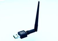
wi-fi adapter
...wi-fi adapter
3dexport
wi-fi for pc!
3d_export
$10
WI GLOWE RIGGING
...wi glowe rigging
3dexport
3d_export
$5

Gun WiS 3D Model
...s оружие пистолет купить download
gun wis 3d model download .c4d .max .obj .fbx .ma .lwo .3ds .3dm .stl ovalera96 106220 3dexport
3d_export
$15

Wi-fi router 3D Model
...ctronics amazing detailed high
wi-fi router 3d model download .c4d .max .obj .fbx .ma .lwo .3ds .3dm .stl artless 109769 3dexport
cg_studio
$30

AMAZON KINDLE FIRE 4 WI-FI3d model
...udio
.3dm .3ds .c4d .wrl - amazon kindle fire 4 wi-fi 3d model, royalty free license available, instant download after purchase.
turbosquid
$15

LG G Pad V500 Wi-Fi tablet
... available on turbo squid, the world's leading provider of digital 3d models for visualization, films, television, and games.
cg_studio
$35

Apple ipad pro wi-fi cellular3d model
...gs .dwg .c4d .3ds .3dm - apple ipad pro wi-fi cellular 3d model, royalty free license available, instant download after purchase.
3d_export
$5
usb wi-fi
...odels distributed in max, obj, mtl, 3ds, fbx formats.<br>after downloading read a text file written in it where what model.
Alarm
archibase_planet
free
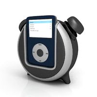
Alarm
...alarm
archibase planet
equipment alarm
alarm ipod - 3d model (*.gsm+*.3ds) for interior 3d visualization.
3d_export
$5

Alarm Clock
...alarm clock
3dexport
alarm clock
3d_export
$5

Alarm Clock
...alarm clock
3dexport
alarm clock
turbosquid
$19

Alarm
...
royalty free 3d model alarm for download as ma, obj, and fbx on turbosquid: 3d models for games, architecture, videos. (1151100)
turbosquid
$20

Alarm
... available on turbo squid, the world's leading provider of digital 3d models for visualization, films, television, and games.
turbosquid
$18
Alarm
... available on turbo squid, the world's leading provider of digital 3d models for visualization, films, television, and games.
turbosquid
$15

Alarm
... available on turbo squid, the world's leading provider of digital 3d models for visualization, films, television, and games.
3d_export
$5
alarm clock
...alarm clock
3dexport
alarm clock made in the style of mid-century modern
design_connected
$9

Alarm Clocks
...alarm clocks
designconnected
karlsson alarm clocks computer generated 3d model. designed by holland vormgevers.
archive3d
free

Alarm 3D Model
...l
archive3d
equipment alarm
alarm ipod - 3d model (*.gsm+*.3ds) for interior 3d visualization.
Laundry
3ddd
$1
Laundry
...laundry
3ddd
laundry
laundry
3ddd
$1
Laundry
...laundry
3ddd
laundry
laundry
3ddd
$1
Laundry
...laundry
3ddd
laundry
laundry
3ddd
$1
Laundry
...laundry
3ddd
laundry
laundry
3ddd
$1
Laundry
...laundry
3ddd
laundry
archibase_planet
free

Laundry basket
...lanet
laundry basket basket clothes basket
laundry basket plastic n180315 - 3d model (*.gsm+*.3ds) for interior 3d visualization.
archibase_planet
free

Laundry basket
...lanet
laundry basket basket baskets clothes basket
laundry basket n180315 - 3d model (*.gsm+*.3ds) for interior 3d visualization.
3ddd
$1
plastic laundry baskets
...plastic laundry baskets
3ddd
plastic laundry baskets , корзина
plastic laundry baskets
3d_export
$5

dirty laundry basket
...dirty laundry basket
3dexport
dirty laundry basket
turbosquid
$40
Laundry Room
...squid
royalty free 3d model laundry room for download as max on turbosquid: 3d models for games, architecture, videos. (1434742)
Fi
3ddd
$1

Fies
...fies
3ddd
смеситель , fies
моделил с каталога
3ddd
$1
wi-fi
...wi-fi
3ddd
wi fi
wi-fi
turbosquid
$5

Sci fi collection (sci fi car, sci fi drone & sci fi corridor)
...& sci fi corridor) for download as 3ds, obj, c4d, and fbx on turbosquid: 3d models for games, architecture, videos. (1432046)
3d_ocean
$9
Hi-Fi
...hi-fi
3docean
hi-fi high-tech highpoly music
i reproduced my hi-fi with blender and rendered with yafaray !
3d_ocean
$25

Sci-Fi Locator
...sci-fi locator
3docean
aerial wire antenna fi future locator sci sci-fi
3d model sci-fi locator by alekrazum vray materials
3d_export
$15
sci fi desktop
...sci fi desktop
3dexport
sci fi desktop
3d_export
$5
Wi-Fi Jammer
...wi-fi jammer
3dexport
глушилка wi-fi
3d_export
$5
sci-fi tech
...sci-fi tech
3dexport
sci-fi asset
3d_export
$5

sci fi corridor
...sci fi corridor
3dexport
sci fi corridor
3d_export
$5
wi-fi adapter
...wi-fi adapter
3dexport
wi-fi for pc!