Thingiverse
Wheeler Filament Handler by trigoprint
by Thingiverse
Last crawled date: 4 years, 4 months ago
Introduction
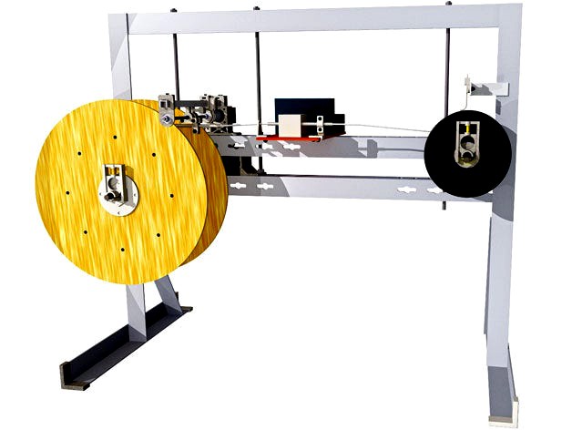
This machine treats your filament right! It allows you to automatically wind the punished filament squeezed on small diameter spool to large diameter comfort spool, or as we call them Wheels. While transfering the filament it can be cleaned, photographed in configurable distances as an option when using the Raspberry PI and the cam.
Our idea was to create a machine to automatically bring the filament to a bigger spool, clean and measure it over all. Despite the coarsely development status it wheels our filament every time needed. Since it is a useful tool with a lot of potential, we thought why not share it with the community?
This started as a test plattform to check different things, you will see some parts in the photos which are no longer in use. The 60/10 gear as an example is from a early stage and looks not very nice, but it works well.
We provide you with a bunch of ideas how it could be, you can use all the data you need from it (see license in code: main_brain.ino!). There are drawings and fotos showing the Wheeler detailed from all sides, a video showing it in action, the source code for the Arduino & Raspberry PI, a stack of 3D-Models to print out or as an inspiration, a parts list, also an electrical diagram and more. It's all free, check it out!
Yes, we know there are still a lot of unfinished items on the Wheeler, but take it as a challange to create your own tailor-made filament handler!
future ideas:
filament endstop switch to stop the Wheeler automatically when the filament ends
better cleaner for filament
better user interface for easy change of parameters
adaptable filament positioning simultaneously with the winding process
new sensor for diameter measurement (instead of camera)
combo power supply for arduino & raspberry PI
webinterface for the measurement part
Detailed notes
Mechanics
The A-axis is the source filament spool and the Z-axis is the drive wheel, so the filament goes from A to Z!
Angle profile used for the framework:
3D-Models
All volumes of printed parts in material list are per part and not cumulated.
We provide 2 sets of parts for this Wheeler since these should be printed in nylon:
wheeler-gear-set (printed in nylon 910)
wheeler-brake-set (printed in nylon 618)
Depending on the object to be printed choose nylon 910 when tension strength is needed or Nylon 618 if abrasion resistance or low friction is the main goal. All other parts can be of diverse material, we still recommend to take something strong. The forces that can occur under certain conditions may destroy weak parts.
A-axis (fixed axis)
You can create specific spool adapters like axis_A_thickening.stl to fit your filament spool. The provided one goes on a 8.2 mm rod and takes taulmann spools (hole dia: 18.8 mm).
Spools can be easily changed with the rod clamp (A-axis wheel stop). The double-face tape is needed to attach the rubber mat to the part "wheel_stop_A_front3.stl".
Wheel brake
To keep the filament under tension use this adjustable brake.
Filament router
The small Nema 11 stepper motor is flexibly coupled to a M5 threaded rod.
Profile to use for the filament router:
Z-axis (driven axis)
The 8mm steel rod (source: old laserprinter or similar) is driven from a Nema 17 stepper motor with a holding torque of 0.44 Nm (62 oz in). Total gear ratio is 1:36 which results in 15.84 Nm.
The coupling to the spool is made with honeycomb adapter. Like on the A-axis there is a rod clamp here too (Z-axis wheel stop). Also the rubber mat is attached to the part "wheel_stop_Z_front2.stl" by double-face tape.
Filament Wheel
These could be made from plywood or any material strong enough. The printed "wheel_Z_bar_X8.stl" has a 1.75mm & 3mm filament fixing hole.
The Wheel parts are not included in the accumulated list.
Electronics
It's very easy to use, just push the ONE button to start wheeling a new spool.
Main brain is the Arduino Nano controlling all the things. The Rapsberry PI camera is connected to it as slave over I2C.
Have a look at the included "Electrical_diagram_Wheeler.pdf" for creation of the perfboard and further information. You have to choose your own case for electronic components! It's best practice to make cables pluggable instead of soldering it directly.
Software
3 pieces of code are available at the moment:
Arduino main brain "main_brain.ino"
Raspberry PI photo slave "photo_slave.py"
Raspberry PI diameter analyzer "diameter_analyzer.py"
The Raspberry PI scripts are based on python, have a look at the header for library information.
Some user settings are prepared in the header of each code.
Needed libraries in arduino code:
"Wire.h" https://www.arduino.cc/en/Reference/Wire
"AccelStepper.h" http://www.airspayce.com/mikem/arduino/AccelStepper/
Camera
A shot taken with the Raspberry PI cam.
Clearly the camera case should be black inside!
LED in electrical diagram is for camera light.
Our setting for the camera measurement are:
filament diameter 3 mm
useable pixel 3mm 492 px
1 pixel 0.006097561 mm
To use the camera startup the wheeler, run
python photo_slave.py
push the ONE button.
All files will be deleted in the filament folder.
you can use ssh or vnc to connect to the Raspberry PI.
To analyze run
python diameter_analyzer.py
Diameter analyzer
The calibration is used to get correct filament measurements.
You will need a precision rod between 1.75mm and 3mm (source could be a dvd drive or similar) for reference.
set calibration to 1
measure your rod with a digital caliper as exactly as possible. the diameter should be the same over the rod.
make a picture of the rod (use the photo_slave.py), check your picture for good quality.
run diameter_analyzer.py to get the pixel count (calibration must be 1)
caluclate the value like this: rod diameter / pixel = calibration
enter this new value as calibration in diameter_analyzer.py