Thingiverse
WeldingRod Bot: Exactly Constrained 3D Printer by Weldingrod1
by Thingiverse
Last crawled date: 2 years, 12 months ago
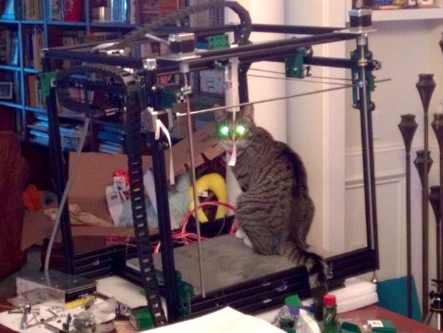
A 3D printer based on the Cobblebot kit or OpenBuilds parts that is not over-constrained - smooth motion with minimal adjustment.
I'm printing now!
The name Cobblebot is the property of Cobblebot Inc. This work uses the kit of parts provided by them for a "Basic", but is radically different from their design.
I'm working on a modified build for the Cobblebot or OpenBuilds parts that will get it closer to an exactly constrained system (and much less sensitive to rail alignment). The target is a 15" cube build volume. Please note that there are both English and Metric versions of most of these drawings. If you get them plasma cut, use 1/8" steel; it cuts REALLY well. If you get them laser or waterjet cut, use whatever you want. They 3d print acceptably, but the end result is kind of floppy; I don't recommend it, but I did try it during my (many) rounds of testing.
Actual motion range:
X: 16" (which means that I can get BOTH heads to move over a 15.2" build area)
Y: 15.5"
Z: 17.5" with a little Y restriction on the front
16.75" for full Y travel
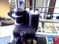
This weekend I assembled version AA of the Mad Scientist (whoops... Engineer) Bot. It is designed to be exactly constrained; no more than one thing controlling each degree of freedom (X, Y, Z, Theta, Phi, and Psi). With no actuators on it, I can grab the extruder carriage rail and wave it around (up and down, in and out) completely freely; WITH NO ADJUSTMENT! That's right, NO tweaking of rail alignment at all! Assembling the frame was amazingly fast!
I'm getting version AD cut today; it deals with mounting motors, belts and end stops. More bulletins to come!
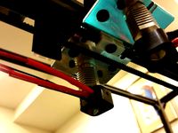
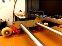
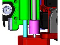
The way it works is there are two Z assemblies, each controlled by a lead screw. Each of them has a long bearing on the front corner post that handles X, Y, Phi, and Psi. A pair of wheels runs on the left and right flat surfaces of the back corner post and controls Theta rotation, but NOTHING else. Z is controlled by the lead screw. The Y carriage has a long bearing on the left horizontal rail that controls X, Z, Theta, and Phi. The other end of the X rail has a pair of bearings running on the flats of the right hand horizontal rail that deals with Psi. I have set the Y drive up where it can either be driven from one side only (the side with the carriage), or driven on both sides using a long 5mm shaft across the front; I'll experiment to see which one I like better. Finally, the X motion is very similar to the stock extruder carrier, except that I moved the extruders really close together and provided a proper belt attachment. The extrusion volume should be close to a 15" cube.
Sorry, I didn't take any photos yet; too excited building!
I did a LOT of tapping the ends; this is a RADICALLY stronger/stiffer connection, if you are willing to do some drilling and tapping. The best choice for tapping the ends is a "gun tap" that pushes the chips ahead of it. McMaster http://www.mcmaster.com/#2703a73/=ymv413 is a good choice.
OK, I assembled rev E night before last (Rev F is going together tonight).
Big stuff:
Optimized all the plates (after initial fitup on AA)
Added motor, idler, and belt attachments
Added the ability to mount the hot ends UNDER the X carriage
Moved everything down to get the hot end to reach the bed
Created Z fittings with two different lowerings (to accomodate those of you that didn't buy 3/8" thick Aluminum beds)
Designed a bed
Designed an insulation holder for the bed
Lessons learned from Rev E:
Corner blocks DO NOT ensure your rails are rotated square to the other rails!
My planned end stop locations interfered with stuff
The belts are kind of short
Parts of the Y ran into the base
My X rail was hard to install
I didn't buy enough idler mounts
The power supply requires moving one of the bottom 20x60 beams over 20 mm
The AG revision is designed, now to get it cut...
Lots of rounds of cut/print, and try... I'm hoping revision AK is the magic one!
I got my Keenovo heater/temperature controller installed this weekend onto my 3/8" thick Aluminum build plate (I know, excessive).
Dang that thing heats fast! When I set it for 40C, I could feel the silicone heater warm up in 1 or 2 seconds! It got to temperature and overshot 2 degrees C in perhaps 10 seconds. The plate, of course, has a lot of catching up to do.
In my "mad scientist/engineer" mode, I couldn't resist adding instrumentation ;-) I have four miniature wire thermocouples set at center, 50, 100, and 150 mm radius and a separate thermistor. I insulated the base plate with Kapton tape, put down the sensors, added another layer of Kapton, then a layer of Copper tape over them for interference protection. I have also designed an insulation retainer for this plate. I promise that I will take some measurements on how even the heating is!
I test fit 3d printed AK version plates this morning; I think I have it now! Mwa-ha-ha-ha!
Ok, AK got the belts almost right, and got the X endstop to work BUT, the Y endstop hit the top frame and the X belt idler hit the top frame. Argh! On to AN and AM.
OK, Revision AP for the frame plates is the winner! The motions line up nicely, run smoothly without adjustment, the belts work, and the limit switches work! Time to start wiring! That, and make the magic stepper motor to shaft connector WITH a timing pulley on it.
The cable chains came out well! Cutting and extending EVERY single wire... Ugh. There is a photo of what the series Z motor harness needs to look like, in case you want to make it the way I did. You can check your Z wiring by shorting each phase and turning one screw to lower the gantry; the other side should lower too. It will NOT raise this way; not enough power output! The motor you are turning acts as a generator and drives the other one. I hope to plug everything in tonight.
Key item: I un-soldered one side of D1 on the RAMPS board to isolate the Mega from +12. I will use a regulator to feed the Mega with 9 Volts to bring down the power dissipation.
Another tip: my prox sensor produces an inverted output. Took a while to diagnose!
I am printing now; the first try on a 20 mm calibration cube looks good!
I printed a test piece with the far side Y belt disconnected to see if that makes any difference in the prints. It BARELY makes any difference. I will put the belt back on, since I already have it in place, but its optional now!
I'm printing now!
The name Cobblebot is the property of Cobblebot Inc. This work uses the kit of parts provided by them for a "Basic", but is radically different from their design.
I'm working on a modified build for the Cobblebot or OpenBuilds parts that will get it closer to an exactly constrained system (and much less sensitive to rail alignment). The target is a 15" cube build volume. Please note that there are both English and Metric versions of most of these drawings. If you get them plasma cut, use 1/8" steel; it cuts REALLY well. If you get them laser or waterjet cut, use whatever you want. They 3d print acceptably, but the end result is kind of floppy; I don't recommend it, but I did try it during my (many) rounds of testing.
Actual motion range:
X: 16" (which means that I can get BOTH heads to move over a 15.2" build area)
Y: 15.5"
Z: 17.5" with a little Y restriction on the front
16.75" for full Y travel
This weekend I assembled version AA of the Mad Scientist (whoops... Engineer) Bot. It is designed to be exactly constrained; no more than one thing controlling each degree of freedom (X, Y, Z, Theta, Phi, and Psi). With no actuators on it, I can grab the extruder carriage rail and wave it around (up and down, in and out) completely freely; WITH NO ADJUSTMENT! That's right, NO tweaking of rail alignment at all! Assembling the frame was amazingly fast!
I'm getting version AD cut today; it deals with mounting motors, belts and end stops. More bulletins to come!
The way it works is there are two Z assemblies, each controlled by a lead screw. Each of them has a long bearing on the front corner post that handles X, Y, Phi, and Psi. A pair of wheels runs on the left and right flat surfaces of the back corner post and controls Theta rotation, but NOTHING else. Z is controlled by the lead screw. The Y carriage has a long bearing on the left horizontal rail that controls X, Z, Theta, and Phi. The other end of the X rail has a pair of bearings running on the flats of the right hand horizontal rail that deals with Psi. I have set the Y drive up where it can either be driven from one side only (the side with the carriage), or driven on both sides using a long 5mm shaft across the front; I'll experiment to see which one I like better. Finally, the X motion is very similar to the stock extruder carrier, except that I moved the extruders really close together and provided a proper belt attachment. The extrusion volume should be close to a 15" cube.
Sorry, I didn't take any photos yet; too excited building!
I did a LOT of tapping the ends; this is a RADICALLY stronger/stiffer connection, if you are willing to do some drilling and tapping. The best choice for tapping the ends is a "gun tap" that pushes the chips ahead of it. McMaster http://www.mcmaster.com/#2703a73/=ymv413 is a good choice.
OK, I assembled rev E night before last (Rev F is going together tonight).
Big stuff:
Optimized all the plates (after initial fitup on AA)
Added motor, idler, and belt attachments
Added the ability to mount the hot ends UNDER the X carriage
Moved everything down to get the hot end to reach the bed
Created Z fittings with two different lowerings (to accomodate those of you that didn't buy 3/8" thick Aluminum beds)
Designed a bed
Designed an insulation holder for the bed
Lessons learned from Rev E:
Corner blocks DO NOT ensure your rails are rotated square to the other rails!
My planned end stop locations interfered with stuff
The belts are kind of short
Parts of the Y ran into the base
My X rail was hard to install
I didn't buy enough idler mounts
The power supply requires moving one of the bottom 20x60 beams over 20 mm
The AG revision is designed, now to get it cut...
Lots of rounds of cut/print, and try... I'm hoping revision AK is the magic one!
I got my Keenovo heater/temperature controller installed this weekend onto my 3/8" thick Aluminum build plate (I know, excessive).
Dang that thing heats fast! When I set it for 40C, I could feel the silicone heater warm up in 1 or 2 seconds! It got to temperature and overshot 2 degrees C in perhaps 10 seconds. The plate, of course, has a lot of catching up to do.
In my "mad scientist/engineer" mode, I couldn't resist adding instrumentation ;-) I have four miniature wire thermocouples set at center, 50, 100, and 150 mm radius and a separate thermistor. I insulated the base plate with Kapton tape, put down the sensors, added another layer of Kapton, then a layer of Copper tape over them for interference protection. I have also designed an insulation retainer for this plate. I promise that I will take some measurements on how even the heating is!
I test fit 3d printed AK version plates this morning; I think I have it now! Mwa-ha-ha-ha!
Ok, AK got the belts almost right, and got the X endstop to work BUT, the Y endstop hit the top frame and the X belt idler hit the top frame. Argh! On to AN and AM.
OK, Revision AP for the frame plates is the winner! The motions line up nicely, run smoothly without adjustment, the belts work, and the limit switches work! Time to start wiring! That, and make the magic stepper motor to shaft connector WITH a timing pulley on it.
The cable chains came out well! Cutting and extending EVERY single wire... Ugh. There is a photo of what the series Z motor harness needs to look like, in case you want to make it the way I did. You can check your Z wiring by shorting each phase and turning one screw to lower the gantry; the other side should lower too. It will NOT raise this way; not enough power output! The motor you are turning acts as a generator and drives the other one. I hope to plug everything in tonight.
Key item: I un-soldered one side of D1 on the RAMPS board to isolate the Mega from +12. I will use a regulator to feed the Mega with 9 Volts to bring down the power dissipation.
Another tip: my prox sensor produces an inverted output. Took a while to diagnose!
I am printing now; the first try on a 20 mm calibration cube looks good!
I printed a test piece with the far side Y belt disconnected to see if that makes any difference in the prints. It BARELY makes any difference. I will put the belt back on, since I already have it in place, but its optional now!
Similar models
thingiverse
free
Cobblebot GT2 Belt Coupler by furicks
... a hole and tapped with a m5 x 0.8 thread. then screwed the short m5 mounting screws through the hole directly into the carriage.
thingiverse
free
K8200 X-belt holder (motor side of carriage) by BY_CRC
...dy of my thing is a derivative of this.
the belt plate was made with chowderhead's great timing belt cogs 'n dogs thingy.
thingiverse
free
XZ Plate Remix by xoxtile
...with double guide rail. whichever you choose, cut two of each.
guide rails attach with 4, 6-32 x .5" and matching lock nuts.
grabcad
free

Shapeoko 3 Linear Rail Carriage Plates
...um stock for adapter plate (atp-5)
0.5" aluminum stock for motor spacer and mount
https://www.thingiverse.com/thing:4183138
thingiverse
free
Rock Solid Prusa X Axis Mounts / Z Wobble Free by TBRIshtar
...n be flexed by the now solid x carriage.
-edit-
uploaded revised models
added a nema17 motor standoff, only if you need it.
thingiverse
free
X-End Carriages with clearance for Z couplers for Zaribo/Haribo by ocieward
...s the tab that hits the x-min limit switch, which i had to reposition do clear the coupler. have fun!
step and stl files attached
thingiverse
free
Cobblebot Proximity Sensor holder by WhiteRatDriver
...riage.
the sensor bolts onto the underside of the x-carriage using one of the through bolts that is used for the belt attachment.
thingiverse
free
Tool to level X-axis of Prusa i3 by mangtronix
... x-axis rod and y-axis rod. then you could hang one of the tools on each side of the x-axis rod and adjust them at the same time.
thingiverse
free
Taz 5 Openbuilds Y axis Plates by discojon
...want. this reinforces the y axis 20x40 rails. i currently am testing a set laser cut from 1/4" acrylic with great success.
thingiverse
free
T5 belt (5mm pitch) fixing plates for CNC machines
...posite end, with a tensioner mechanism.
openscad file included so you can modify as needed.https://www.ebay.co.uk/usr/metalgodltd
Weldingrod
thingiverse
free
Universal Carbon Yagi Antenna - only 20€! by Tysonpower
...and the two elements you need the following materials: weldingrod ø 2mm cable with connector (i used rg-59 with...
thingiverse
free
Huxley E3D Lite6 Mount (with GT2 Belt clamp X-carriage) v0.9 by hugofitz
...are easier to print! the x-cariage is remixed from weldingrod#39;s design to allow the use of a gt2 belt...
3dwarehouse
free

AGRU_40410000030_ECTFE natur_Schweissdraht_3mm_110
...#logocad #megacad #one_space_designer #online_3d_part_library #partsolutions #proe_wildfire #solidedge #solidworks #unigraphics #weldingrod ...
3dwarehouse
free

AGRU_10410000030_PPB 2222 grau_Schweissdraht_3mm_110
...#logocad #megacad #one_space_designer #online_3d_part_library #partsolutions #proe_wildfire #solidedge #solidworks #unigraphics #weldingrod ...
3dwarehouse
free

AGRU_40410000030_ECTFE natur_Schweissdraht_3mm_110
...#logocad #megacad #one_space_designer #online_3d_part_library #partsolutions #proe_wildfire #solidedge #solidworks #unigraphics #weldingrod ...
Weldingrod1
thingiverse
free
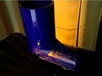
Cowboy Boot by Weldingrod1
...verse
i needed a model of a cowboy boot so i could wrap something to go with a "get a new pair of boots" certificate.
thingiverse
free

Christmas tree topper/star by Weldingrod1
...christmas tree topper/star by weldingrod1
thingiverse
this is a stellated dodecahedron to fancy up your tree!
thingiverse
free
Drying stand for nasal irrigator by Weldingrod1
...d for nasal irrigator by weldingrod1
thingiverse
this is a stand that fits the neilmed nasal irrigator and allows it to drip dry
thingiverse
free

Hand Punch Hangers by Weldingrod1
...omized to fit the two smaller sizes of whitney brand hand punches. the smaller one will fit the harbour freight hand punch also.
thingiverse
free
Stackable extruder by Weldingrod1
...s (oriented for the huxley) and are arranged to be stackable. the one that takes markers would, of course, use white filament...
thingiverse
free
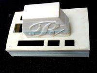
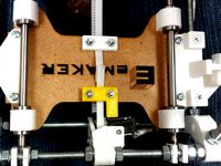
Emaker Huxley electronics enclosure by Weldingrod1
...d to work with the emaker huxley electronics. it clears the sd card and accomodates the connector orientation used on the huxley
thingiverse
free

Milwaukee close quarters drill hangar by Weldingrod1
...od1
thingiverse
this is a custom fitted hangar for a milwaukee close quarters drill. it will probably fit the other brands too.
thingiverse
free
Y belt clamp with end stop by Weldingrod1
...y weldingrod1
thingiverse
if you replace your y axis belt clamp with this it will provide a place for the limit switch to touch.
thingiverse
free
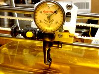
Indicator Holder for Emaker Huxley print head by Weldingrod1
...huxley print head by weldingrod1
thingiverse
this will let you mount a test indicator on your huxley to really level up the bed!
thingiverse
free

Tape hangars by Weldingrod1
...ts and double units. the double unit is sized for two full size rolls to fit properly.
they stick up nicely with command strips.
Constrained
3d_export
$50
ball joint dollolive
...joint dollolive 3dexport all parts have been separated and constrained you can print it out and assemble it right...
3d_export
$5

bearing
...ng. it is a machine element that constrains relative motion to only the desired motion, and reduce friction between moving parts.
3d_export
$30
rigged wardrobe
...min/max rotations constrained.<br>drawer - min/max location constrained.<br>root - location/rotation constrained<br>.blend - native<br>.fbx<br>.obj<br>wardrobe<br>armature<br>wgt_shapes (custom bone shapes for .blend file) wgt_door...
3d_export
$40
rigged grandfather clock
...- contstrained to translate and rotate on floor.<br>minute-hand - constrained to rotate on clockface.<br>hour-hand - constrained to rotate on...
3d_export
$30
rigged coffee table
...marmoset viewer, eevee and cycles.<br>root (moves entire model)<br>topdrawer - constrained to move along local y(forward) axis 50cm out, in...
3d_export
$10
englands glory vintage matchbox
...real world scales.<br>fully and efficiently uv unwrapped.<br>game ready.<br>rigged and constrained for easy placement and opening and closing of the...
3d_export
$30

gold pocket watch
...and close no more than 0°. the winder is constrained to only rotate along it's local axis.<br>.blend - native<br>.fbx...
3d_export
$20
rigged folding pocket lock knife
...up inspection) animations and movies.<br>root (moves entire model)<br>blade - constrained to rotate on local z axis with min/max stops...
3d_export
$24

pirate treasure chest
...closed, or fill with your own loot.<br>.blend (native, with constrained rigging)<br>.fbx<br>.obj<br>.dae<br>chest (collection)<br>chest_rig<br>chest (3584 faces)<br>coins (11760 faces)<br>lid (1753 faces)<br>padlock (316...
3d_export
$8

black alloy racing wheels - blender
...them turning in the z axis. this empty is constrained in the z axis from -60 degrees to +60...
Bot
turbosquid
$19

Bot
... available on turbo squid, the world's leading provider of digital 3d models for visualization, films, television, and games.
turbosquid
free

Bot
... available on turbo squid, the world's leading provider of digital 3d models for visualization, films, television, and games.
3d_export
$10

scanner bot
...scanner bot
3dexport
cool scanner bot who scans for fixing things...
3d_ocean
$9

Apc Bot
...n bot games toys
an all-purpose-constructo-bot. for cartoon purposes. the model is not rigged. please use vray adv for rendering.
3d_export
$75

Bot 3D Model
...bot 3d model
3dexport
robot bot man kiborg character
bot 3d model evgen 19504 3dexport
turbosquid
free

Eye Bot
...eye bot
turbosquid
free 3d model eye bot for download as fbx on turbosquid: 3d models for games, architecture, videos. (1514059)
turbosquid
$29

Gorill-bot
...bosquid
royalty free 3d model gorill-bot for download as fbx on turbosquid: 3d models for games, architecture, videos. (1239456)
turbosquid
$25

Lamp Bot
...bosquid
royalty free 3d model lamp bot for download as blend on turbosquid: 3d models for games, architecture, videos. (1230121)
turbosquid
$10
Spectre Bot
...osquid
royalty free 3d model spectre bot for download as fbx on turbosquid: 3d models for games, architecture, videos. (1616378)
turbosquid
$8

Ultra Bot
...urbosquid
royalty free 3d model ultra bot for download as ma on turbosquid: 3d models for games, architecture, videos. (1330752)
Exactly
3d_export
$20
vernier calipper
...vernier calipper 3dexport vernier cvalipper made as real, exactly ...
3d_export
$16

pan
...pan 3dexport this pan model is exactly for the interior of your kitchen and for the...
3d_export
$10
GEARBOX REPAIR KIT AUDI 100 C3
...repair kit audi 100 c3 3dexport all details are exactly copied from the original. applicable: - audi 100...
3d_export
$5

Boots
...make their adventure even more memorable? then this is exactly what you...
3d_export
$15

audi tts
...audi tts 3dexport audi tts. the machine is exactly a copy of the original. in addition to the...
3d_export
$5
bosch hand mixer
...with rhino 3d using surface modeling tools. it is exactly like the real object with all it's details, the...
3d_export
$8

of a cage for parrots
...cage for parrots the dimensions of the glasses are exactly the same as the original. the idea was completely...
3d_ocean
$16

iPad 2
...ipad 2 is so new, it’s difficult to know exactly how it...
3d_export
$7
3d model of sports simulator
...of sports simulator. the dimensions of the glasses are exactly the same as the original. the idea was completely...
3d_export
$8

of a cannon
...of the cannon. the dimensions of the glasses are exactly the same as the original. the idea was completely...
Printer
archibase_planet
free
Printer
...inter
archibase planet
printer laser printer pc equipment
printer n120614 - 3d model (*.gsm+*.3ds) for interior 3d visualization.
archibase_planet
free
Printer
...rchibase planet
laser printer office equipment computer equipment
printer - 3d model (*.gsm+*.3ds) for interior 3d visualization.
turbosquid
$100

Printer
...er
turbosquid
royalty free 3d model printer for download as on turbosquid: 3d models for games, architecture, videos. (1487819)
turbosquid
$3
Printer
...turbosquid
royalty free 3d model printer for download as max on turbosquid: 3d models for games, architecture, videos. (1670230)
turbosquid
$1
printer
...turbosquid
royalty free 3d model printer for download as max on turbosquid: 3d models for games, architecture, videos. (1595546)
turbosquid
$1
printer
...turbosquid
royalty free 3d model printer for download as max on turbosquid: 3d models for games, architecture, videos. (1595105)
turbosquid
$7
Printer
...royalty free 3d model printer for download as ma, ma, and obj on turbosquid: 3d models for games, architecture, videos. (1644580)
turbosquid
$30
Printer
... available on turbo squid, the world's leading provider of digital 3d models for visualization, films, television, and games.
turbosquid
$20
Printer
... available on turbo squid, the world's leading provider of digital 3d models for visualization, films, television, and games.
turbosquid
$18
printer
... available on turbo squid, the world's leading provider of digital 3d models for visualization, films, television, and games.