Thingiverse
W2D-IV Trailing ARM Mod by WrenchToDrive
by Thingiverse
Last crawled date: 3 years ago
Hi guys,
Warning: If you have problems with part strength, be prepared to do some work on your print process if you want to have success running this crawler. It is BIG and the parts need to be strong. I had my first experience with bad (brittle) PLA while testing this and I now understand the bad experiences that some people have had. My next buy is going to be PLA+ because the added flexibility should help a lot. I'm using a batch of Solutech that I got dirt cheap, but some of it is terrible and some not bad, so take that for what you will. I found the old Amazon Basics PLA to be quite strong, for what that's worth.
To get strong parts: Make them solid. Print them lying down. Use a criss cross infill pattern. Play with the heat to get it as high as you can without the plastic going brittle. Usually, right about where the stringing starts is good for me. Zero stringing is not the strongest part IMO. Over extrusion is better than under extrusion. Your mileage may vary.
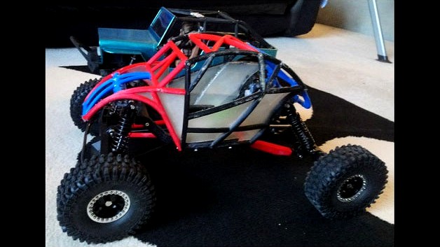
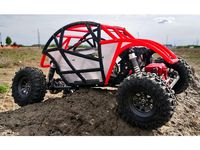
This is a suspension mod for my W2D-IV Baja Racer. I'm running these parts with the Redcat XR247 (Wendigo) Axle kit but any wide axles should work with a little DIY.
See it running: https://www.youtube.com/watch?v=FjeaudXrbwM
See it breaking: https://www.youtube.com/watch?v=MjZcI0Bl2tY
Baja Racer: https://www.thingiverse.com/thing:4597812
I used longer than normal M4x20mm grub screws to attach standard crawler link ends to the rear arms but regular ones should work. My thinking was that longer would make the arms stronger.
The rear trailing arm and link mounts sandwich around the chassis rail with the rear screw used to mount the trailing arm. 2x M3x20mm screws. The upper link uses an M3 screw.
You'll need a LONG rear drive shaft. I used a hex slider one and modded it for more length using a long allen wrench. Cut off the 90 degree end of the long allen wrench and use that in place of the stock slider. See my how to video: https://www.youtube.com/watch?v=q1cafR62I2U
The inboard servo started as a temporary work around but it seems to work well so I'm leaving it for now. I had to DIY the front linkage. The servo mounts sandwich around the chassis rail as shown in the picture and the servo attaches to the mount.
If you are running XR247 axles, use Str_Axle_Mnt.stl and attach it to the axle on the right side of the pumpkin using the existing hole. Attach the Str_Crank.stl to the mount. Str_Crank_V2.stl has a larger hole for use with a bushing. I had some shock spacers kicking around that worked, so your mileage may vary. I used a soldering iron to press the bushing in like a threaded insert and it seems to be working well. Bearings would be better but I haven't gotten around to that yet.
Link lengths are hole to hole and approximated (measured on the car):
Front steering: 80mm
Center steering: 100mm
Front lower: 130mm
Front upper: 125mm
Rear lower: 122mm
Rear upper: 135mm
Drive shafts:
Front: 130mm
Rear: 165mm
Drive to wrench or wrench to drive?
Warning: If you have problems with part strength, be prepared to do some work on your print process if you want to have success running this crawler. It is BIG and the parts need to be strong. I had my first experience with bad (brittle) PLA while testing this and I now understand the bad experiences that some people have had. My next buy is going to be PLA+ because the added flexibility should help a lot. I'm using a batch of Solutech that I got dirt cheap, but some of it is terrible and some not bad, so take that for what you will. I found the old Amazon Basics PLA to be quite strong, for what that's worth.
To get strong parts: Make them solid. Print them lying down. Use a criss cross infill pattern. Play with the heat to get it as high as you can without the plastic going brittle. Usually, right about where the stringing starts is good for me. Zero stringing is not the strongest part IMO. Over extrusion is better than under extrusion. Your mileage may vary.
This is a suspension mod for my W2D-IV Baja Racer. I'm running these parts with the Redcat XR247 (Wendigo) Axle kit but any wide axles should work with a little DIY.
See it running: https://www.youtube.com/watch?v=FjeaudXrbwM
See it breaking: https://www.youtube.com/watch?v=MjZcI0Bl2tY
Baja Racer: https://www.thingiverse.com/thing:4597812
I used longer than normal M4x20mm grub screws to attach standard crawler link ends to the rear arms but regular ones should work. My thinking was that longer would make the arms stronger.
The rear trailing arm and link mounts sandwich around the chassis rail with the rear screw used to mount the trailing arm. 2x M3x20mm screws. The upper link uses an M3 screw.
You'll need a LONG rear drive shaft. I used a hex slider one and modded it for more length using a long allen wrench. Cut off the 90 degree end of the long allen wrench and use that in place of the stock slider. See my how to video: https://www.youtube.com/watch?v=q1cafR62I2U
The inboard servo started as a temporary work around but it seems to work well so I'm leaving it for now. I had to DIY the front linkage. The servo mounts sandwich around the chassis rail as shown in the picture and the servo attaches to the mount.
If you are running XR247 axles, use Str_Axle_Mnt.stl and attach it to the axle on the right side of the pumpkin using the existing hole. Attach the Str_Crank.stl to the mount. Str_Crank_V2.stl has a larger hole for use with a bushing. I had some shock spacers kicking around that worked, so your mileage may vary. I used a soldering iron to press the bushing in like a threaded insert and it seems to be working well. Bearings would be better but I haven't gotten around to that yet.
Link lengths are hole to hole and approximated (measured on the car):
Front steering: 80mm
Center steering: 100mm
Front lower: 130mm
Front upper: 125mm
Rear lower: 122mm
Rear upper: 135mm
Drive shafts:
Front: 130mm
Rear: 165mm
Drive to wrench or wrench to drive?
Similar models
thingiverse
free

Simple micro 8x8 Chassis by Leiywen
... or glue (i used mixture of pads and glue.
as i said, it's a simple design, but does need some work to get it up and running.
thingiverse
free

W2D-V Hammer Jammer Slammer Whammer Blammer Truck by WrenchToDrive
... so good but i kinda think it won't last. we shall see.
as always, use at your own risk.
wrench to drive or drive to wrench?
thingiverse
free

Clod Buster servo mount
...weak areas.
mounting holes may need finishing with a 3mm drill bit. servo holes will need to be drilled according to your servo.
thingiverse
free
W2D IV - Baja Racer by WrenchToDrive
...use the parts from a wltoys 12428 or something similar pretty easily with your biggest problem being mounting the...
thingiverse
free

iFlight XL5 GoPro Hero 5/6/7 35 degree mount
...driving screws at an angle, as shown in the attached pic).
original sketchup designs are attached for further remixing, enjoy! :)
thingiverse
free

Servo Mount by AlexGale
...the hole is (in the front), the screw goes through the hole. someone (in the comments) reccomended to use the screw size 4 x 3/8.
thingiverse
free

AR45 Servo on axle mount by lgalkis
...this because im not sure about the rigity but it a good starting point. the ar45 axle is not so soa friendly but its something :)
thingiverse
free

Axle Servo Mount SCX10 II Version 1 by domi1974
...om behind the pumpkin with 4 screws.
here is another way to mount the servo on the axle.https://www.thingiverse.com/thing:2666683
thingiverse
free

RedCat Gen 7 Front ESC/Receiver Mount by SimpleSine
...e post backward. you need to remove the battery tray to do this. the mount just rests on the top of the screws still very secure.
thingiverse
free

6DOF Robot arm by ThatNewMaker_101
...on the bracket and then screw in the servo with m4 screws and nuts.
attach the gripper to the last servo with m3 screws and nuts.
W2D
thingiverse
free
W2D-V Hammer Jammer Slammer Whammer Blammer Truck by WrenchToDrive
... so good but i kinda think it won't last. we shall see.
as always, use at your own risk.
wrench to drive or drive to wrench?
thingiverse
free
W2D IV - Baja Racer by WrenchToDrive
...chassis mods are likely to follow to make it more versatile.
as always, use at your won risk.
wrench to drive or drive to wrench?
thingiverse
free

W2D-VI Bronco Style SCX10 Clone Body by WrenchToDrive
...s://www.thingiverse.com/thing:4588243
rear bumper: https://www.thingiverse.com/thing:4653515
wrench to drive or drive to wrench?
cg_trader
free

W2D
...th vray 3.00 wall cabinet 2 door - multiple door styles allow for use as kitchen cabinets, school cabinets, insitutional cabinets
3dwarehouse
free

ARCO W2D
...arco w2d
3dwarehouse
3dwarehouse
free

W2D
...ary #custom #customizable #dc #door #dynamic_component #european #frameless #kitchen #option #options #school #wall #wall_cabinet
3dwarehouse
free

W2D2760 Wall Cabinet Woodharbor
...all cabinet woodharbor full flush inset door style: madison #27 #60 #full_flush_inset #madison #w2d2760 #wall_cabinet #woodharbor
Wrenchtodrive
thingiverse
free

Kyosho Fazer MK2 Front Bumper by WrenchToDrive
...it works well in tpu but my first version was pla and has held up well.
use at your own risk.
wrench to drive or drive to wrench?
thingiverse
free

Arrma Senton Roof Slider by WrenchToDrive
...;m not so sure about. your mileage may vary.
attach with 2-sided tape.
use at your own risk.
wrench to drive or drive to wrench?
thingiverse
free

Redcat Gen 8 SCX10 Metal Axle Panhard Mount by WrenchToDrive
... hold it in place.
summary and run video: https://youtu.be/zj-lojcs2sw
use at your own risk.
wrench to drive or drive to wrench?
thingiverse
free

SCX10 Jeep Bumper by WrenchToDrive
... trx-4 rails are the same as scx10 except that the channels are deeper.
use at your own risk.
wrench to drive or drive to wrench?
thingiverse
free

SCX10 Clone Crawler Stealth(ish) Rear Bumper by WrenchToDrive
... the mount kit for improvements. i expect the bumpers will not change.
use at your own risk.
wrench to drive or drive to wrench?
thingiverse
free

Kyosho Fazer MK2 Rear Suspension by WrenchToDrive
... a charger daytona/plymouth super bird front end and wing...
as always, use at your own risk.
drive to wrench or wrench to drive?
thingiverse
free

Generic roof slider (For RC car) by WrenchToDrive
... bit and they are more durable than i expected. your mileage may vary.
use at your own risk.
wrench to drive or drive to wrench?
thingiverse
free

SCX10 Tube Style Bumper by WrenchToDrive
...o, you'll just need to mount the bumper to it with screws and nuts.
use at your own risk.
wrench to drive or drive to wrench?
thingiverse
free

SCX10 (Clone) Tube Front Bumper LED Ready by WrenchToDrive
...k the mount kit for improvements. i expect the bumpers will not change.
use at your own risk.
wrench to drive or drive to wrench?
thingiverse
free

Jeep Front and Rear Inner Fenders by WrenchToDrive
...mment and let me know. i don't consider a little trimming heinous.
use at your own risk.
wrench to drive or drive to wrench?
Trailing
3d_export
$10

trailing ivy
...trailing ivy
3dexport
trailing ivy
3d_export
$10

trailing ivy 2
...trailing ivy 2
3dexport
trailing ivy 2
3d_export
$10

trailing ivy 3
...trailing ivy 3
3dexport
set trailing ivy 3.
turbosquid
$10

trail 1
... available on turbo squid, the world's leading provider of digital 3d models for visualization, films, television, and games.
3d_export
$16

Nissan x-trail t32
...nissan x-trail t32
3dexport
nissan x-trail t32 for 3d printing
3d_export
$15

Marble trail 3D Model
...rt
marble trail bridge мрамор
marble trail 3d model download .c4d .max .obj .fbx .ma .lwo .3ds .3dm .stl trueline 109495 3dexport
3d_export
$65

tree-lined trail
...tree-lined trail
3dexport
simple rendering of the scene file
3d_export
$40

Nissan X-trail 3D Model
...nissan x-trail 3d model
3dexport
car x-trail nissan suv cars auto instaauto 2011
nissan x-trail 3d model llirik 101209 3dexport
3d_ocean
$3

Beach Sand with Bird Trails
... a beach for game development and 3d modelling art. 1 color and 1 bump file in png format, made from 100% original photo content.
3d_ocean
$89

Nissan X-Trail 2011
...y, in real units of measurement, qualitatively and maximally close to the original. model formats: - *.max (3ds max 2008 scanl...
Iv
turbosquid
$30

ive
... available on turbo squid, the world's leading provider of digital 3d models for visualization, films, television, and games.
3ddd
$1

Towel Collection IV
...towel collection iv
3ddd
полотенце
towel collection iv
3ddd
$1

Kitchen Furniture IV
...kitchen furniture iv
3ddd
kitchen furniture iv
s = 10m2
turbosquid
$100

Panzer IV
...lty free 3d model panzer iv for download as obj, fbx, and stl on turbosquid: 3d models for games, architecture, videos. (1421378)
turbosquid
$60

Mark IV
...oyalty free 3d model mark iv for download as ma, obj, and fbx on turbosquid: 3d models for games, architecture, videos. (1515462)
3d_export
$29

PzKpfw IV 3D Model
...pzkpfw iv 3d model
3dexport
tank german pzkpfw iv t-iv medium
pzkpfw iv 3d model ivan454 98094 3dexport
turbosquid
$99

Merkava IV
... available on turbo squid, the world's leading provider of digital 3d models for visualization, films, television, and games.
turbosquid
$49

IV Injection
... available on turbo squid, the world's leading provider of digital 3d models for visualization, films, television, and games.
turbosquid
$20

column IV
... available on turbo squid, the world's leading provider of digital 3d models for visualization, films, television, and games.
turbosquid
$19

Iv Pole
... available on turbo squid, the world's leading provider of digital 3d models for visualization, films, television, and games.
Mod
design_connected
$13

MOD. 4233 - MOD. 4234 Table Lamp
...mod. 4233 - mod. 4234 table lamp
designconnected
arcahorn mod. 4233 - mod. 4234 table lamp computer generated 3d model.
design_connected
$11

MOD.1095
...mod.1095
designconnected
mod.1095 computer generated 3d model. designed by sarfatti, gino.
3ddd
$1

fireplaces mod Spec
...fireplaces mod spec
3ddd
камин
fireplaces mod spec 180x90x125h
3ddd
free

Flos Mod. 2129
... mod
фабрика: flos
модель: mod. 2129
описание: подвесной светильник, металл, белый, черный.
сайт: www.flos.com
turbosquid
$34

Mod Lamp.c4d
... available on turbo squid, the world's leading provider of digital 3d models for visualization, films, television, and games.
turbosquid
$32
MOD A 001
... available on turbo squid, the world's leading provider of digital 3d models for visualization, films, television, and games.
turbosquid
$29

Maars Mod
... available on turbo squid, the world's leading provider of digital 3d models for visualization, films, television, and games.
turbosquid
$15

Mod 70..
... available on turbo squid, the world's leading provider of digital 3d models for visualization, films, television, and games.
turbosquid
$10

MOD Sofa
... available on turbo squid, the world's leading provider of digital 3d models for visualization, films, television, and games.
turbosquid
$1

Mod-Lite
... available on turbo squid, the world's leading provider of digital 3d models for visualization, films, television, and games.
Arm
archibase_planet
free

Arm
...ase planet
arm hand right hand skeleton
arm human skeleton right arm n030515 - 3d model (*.gsm+*.3ds+*.max) for 3d visualization.
3ddd
$1

arm chair
...arm chair
3ddd
arm chair , пуф
arm chair
turbosquid
$5
arm
...arm
turbosquid
royalty free 3d model arm for download as obj on turbosquid: 3d models for games, architecture, videos. (1306158)
turbosquid
free

Arm
...arm
turbosquid
free 3d model arm for download as obj and fbx on turbosquid: 3d models for games, architecture, videos. (1346955)
turbosquid
$29

Arm
...osquid
royalty free 3d model arm for download as obj and fbx on turbosquid: 3d models for games, architecture, videos. (1382436)
3d_export
$5

coat of arms
...coat of arms
3dexport
coat of arms
3ddd
$1

ARM SOFA
...arm sofa
3ddd
arm sofa
3ddd
$1

Arm chair
...arm chair
3ddd
arm chair
3ddd
$1

Arm chair
...arm chair
3ddd
угловое
arm chair
3ddd
$1
ARM CHAIR
...arm chair
3ddd
arm chair clothes