GrabCAD
Viewpoint Reference Block
by GrabCAD
Last crawled date: 1 year, 11 months ago
This model has become somewhat obsolete, since Solidworks has now an improved Viewpoint functionality, nevertheless I leave it here...
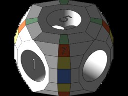
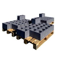
And here my favorite (and oldest) tool for use in SolidWorks, finally decided that others might find this useful, too: Its a cube to create named viewpoints for later use in Drawings. Import this into your model then: Hold CTRL, then 1st left-click on the face you want to look at (direction) then 2nd left-click on the face you want to appear above in your view (orientation) then trigger the NORMAL-TO command. Save the thus created view under a name of your choice, delete this cube again, save the model and voila: it becomes available in SldDrw as a named view. This is much faster and more repeatable than manipulating view orientations in a SldDrw view manually. Example in SldWrks: Hold CTRL, LC the orange face no.7, then LC the adjacent green face, NORMAL-TO and you get the same view as the ISO-VIEW command will give.
When inserted into a SldPrt or SldAsm model with axes aligned (which is the default): Face no.1 marks the standard FRONT view, no.5 the standard TOP view and no.7 the standard ISO View. All other orange faces give the ISO view from any (here virtual) corner of the cube. The yellow ones are 15° above the XZ plane, the green ones parallel to XZ, but 15° lower than the XZ-normal. These later ones are very handy for explosion views. Very rarely, I still need manual modification of the view (a little more here, a little more there) but this I do then from a well defined starting point.
Remember: good technical drawings contain at least 1, better 2 isometric views, particularly for complex milled pieces and sheet metal parts.
Similar models
thingiverse
free

Cubic Fractal +4 by threonin
...cubic fractal +4 by threonin
thingiverse
i added four more child cubes to each face one recursion later.
3dwarehouse
free

Commander Slash (cube man spy)
...de of his face is evidence that he use to be a regular solider. his duty now is to asasinate and spy on the leaders of the cubea.
thingiverse
free

Cubic Fractal +8 by threonin
...cubic fractal +8 by threonin
thingiverse
this time i added eight more child cubes to each face one recursion later.
3dwarehouse
free

Stone Pyramid (New View)
...stone pyramid (new view)
3dwarehouse
testing to see if google warehouse saves the sketchup viewpoint #pyramid_textures
3dwarehouse
free

Left Cube 2.0
...left cube 2.0
3dwarehouse
left-facing cube made with components
3dwarehouse
free

HUMMER H3
...tuned models of the hummer h3 left here. author is tigreferoce. i fixed some wrong oriented faces, now 3d-view should looks fine.
thingiverse
free

key cap left ctrl - Tecla Ctrl izquierda Logitech G413 by Necro3D
...p left ctrl - tecla ctrl izquierda logitech g413 by necro3d
thingiverse
key cap left ctrl - tecla ctrl izquierda logitech g413..
3dwarehouse
free

Rubik's Cube
... one for every stonetype and one for the names. six colors: white/ yellow, red/ orange, blue/ green #cube #eno_rubik #rubiks_cube
grabcad
free

AutoCAD - Complete Tutorial for Beginners - Exercises 11
...r channel for more videos & projects in solidworks & dont forget to hit like & share the videos, thanks for watching.
grabcad
free

AutoCAD - Complete Tutorial for Beginners - Exercises 1
...r channel for more videos & projects in solidworks & dont forget to hit like & share the videos, thanks for watching.
Viewpoint
3d_export
$5

monument- totem- viewpoint- pedestrian tower
...ewpoint- triangular pedestrian tower. modeled in sketchup, total height 18 m.<br>available for obj, 3ds, collade, fbx, skp.
3d_ocean
$6

Low Poly Pumpkins
...down perspectives but can also be used for lower viewpoint ...
3d_ocean
$9

Low Poly Well
...down perspectives but can also be used for lower viewpoint angles. the...
3d_ocean
$19

Rock Formation Pack 3
...down perspectives but can also be used for lower viewpoint angles. all models are...
3d_ocean
$4

Low Poly Grass Pack
...down perspectives but can also be used for lower viewpoint ...
3d_ocean
$19

Rock Formation Pack 2
...down perspectives but can also be used for lower viewpoint angles. all...
3d_ocean
$19

Rock Formation Pack 1
...down perspectives but can also be used for lower viewpoint angles. perfect for your next game...
3d_ocean
$9

Rock Formation Pack 4
...down perspectives but can also be used for lower viewpoint angles. all models are low poly and...
3d_ocean
$6

Low Poly Fence Set 02
...down perspectives but can also be used for lower viewpoint angles. ideal for decorating...
3d_ocean
$6

Low Poly Fence Set 01
...down perspectives but can also be used for lower viewpoint angles. ideal for decorating...
Reference
turbosquid
$1

horse reference
...id
royalty free 3d model horse reference for download as max on turbosquid: 3d models for games, architecture, videos. (1332096)
turbosquid
$1

Hyena reference
...id
royalty free 3d model hyena reference for download as max on turbosquid: 3d models for games, architecture, videos. (1180809)
turbosquid
$15
Body reference
...alty free 3d model body reference for download as fbx and obj on turbosquid: 3d models for games, architecture, videos. (1583572)
turbosquid
$20

Reference Monitor
... available on turbo squid, the world's leading provider of digital 3d models for visualization, films, television, and games.
3ddd
free
Аудио колонки - KEF - Reference
...аудио колонки - kef - reference
3ddd
kef , колонки
аудио колонки - kef - reference
turbosquid
$1

Lion reference
...ce
turbosquid
royalty free 3d model lion for download as max on turbosquid: 3d models for games, architecture, videos. (1180287)
turbosquid
$20

Female Reference+3D
... available on turbo squid, the world's leading provider of digital 3d models for visualization, films, television, and games.
turbosquid
$20

Klipsch Reference RS62
... available on turbo squid, the world's leading provider of digital 3d models for visualization, films, television, and games.
turbosquid
$20
Klipsch Reference RS52
... available on turbo squid, the world's leading provider of digital 3d models for visualization, films, television, and games.
turbosquid
$20

Klipsch Reference RS42
... available on turbo squid, the world's leading provider of digital 3d models for visualization, films, television, and games.
Block
archibase_planet
free

Blocks
...blocks
archibase planet
blocks bricks toy
toy blocks - 3d model (*.gsm+*.3ds) for interior 3d visualization.
3d_export
$5

Block
...block
3dexport
3d_export
$10
The guillotine and the block
...the guillotine and the block
3dexport
the guillotine and the block autocad 2013
3d_ocean
$8
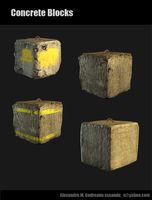
Concrete Blocks
... blocks, barriers or cover for characters during a fire fight. each one has its own diffuse map, specular and normal map in tg...
archibase_planet
free
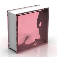
Glass block
...glass block
archibase planet
glass block brick
glass block n211009 - 3d model (*.gsm+*.3ds) for interior 3d visualization.
3d_export
$99

city block
...city block
3dexport
city block 3d model. include max, obj and fbx files.
3d_ocean
$3
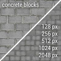
Concrete Blocks Textures
...res
3docean
block blocks concrete seamless wall walls
a couple of seamless textures with two differents sizes of concrete blocks.
3d_export
$5

plummer block
...plummer block
3dexport
this is an 3d model of plummer block assembly where seven parts are required to assemble this.
design_connected
$16

Block 2
...block 2
designconnected
henry pilcher block 2 computer generated 3d model. designed by pilcher, henry.
3d_export
$7
concrete blocks on pallets
...concrete blocks on pallets
3dexport
concrete blocks on pallets, 3 types of blocks. there are all the necessary textures.