Thingiverse
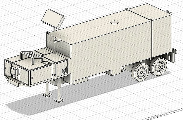
USAF GLCM Launch Control Center by ronaldcaudillo
by Thingiverse
Last crawled date: 3 years, 3 months ago
This is the third model of three for the USAF GLCM series.
MAN Tractor- https://www.thingiverse.com/thing:4561497
Transporter-Erector Launcher- https://www.thingiverse.com/thing:4576098
The USAF mobile Ground Launched Cruise Missile was developed as a counter to the mobile medium- and intermediate- range ballistic nuclear missiles deployed by the Soviet Union in Eastern Bloc European countries. The USAF GLCM and the US Army's Pershing II were the incentives that fostered Soviet willingness to sign the Intermediate-Range Nuclear Forces Treaty (INF treaty), and reduced the threat of nuclear wars in Europe. It was deployed during 1983 and fully removed from service by 1991. I served as an assistant flight chief assigned to the 487th Tactical Missile Wing at Comiso Air Station, Sicily.
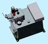
The Launch Control Center (LCC) was man armored trailer manned by two launch control officers contained in the sheltered trailer box. The aft box housed air handling and chemical and biological filters. When the LCC is connected to Transporter-Erector Launcher (TEL) and received valid and verified launch orders, executed launch sequence procedures for the GLCM cruise missiles housed inside the TEL. The LCC had several antenna systems for communication with each other and to USAF HQ. There are 3 whip type antennas (see included diagram) that are too thin to print. You can use thin wire for these. Cut them to approximately 1/3 the shelter box (minus the aft equipment box. Heat up the end of the wire, and press into each of the small cubes on three top corners of the LCC Shelter. I have provided a small, vertical holes in the top of each of these cubes to assist you.
The legs were used to support an LCC that is disconnected from the prime mover. I have included replaceable legs- Leg Up when the LCC is joined to the prime mover, and Leg Down when the TEL is disconnected from the prime mover (or you just want more model stability).
For the LCC model, you will need to print the following:
1 x LCC 3D Ladder
2 x LCC 3D Leg Down
2 x LCC 3D Leg Up
1 x LCC 3D UHF Antenna
1 x LCC 3D UHF Mast
1 x LCC 3D UHF Support
1 x LCC 3D
4 x Trailer Wheel
The models are real world size to make it easier to print to a desired scale.
Resize to:
0.4545% (1:220 scale, model railroad Z scale)
L=2.16", W=0.46", H=1.03"
0.5000% (1:200 scale)
L=2.38", W=0.51", H=1.14"
1.0000% (1:100 scale)
L=4.76", W=1.01", H=2.28"
1.1494% (1:87.1 scale, model railroad HO scale)
L=5.47", W=1.16", H=2.62"
1.3889% (1:72 scale)
L=6.61", W=1.40", H=3.16"
1.5625% (1:64 scale, Hot Wheels and Matchbox scale)
L=7.44", W= 1.58",H=3.58"
2.0833% (1:48 scale)
L=9.92", W=2.10", H=4.74"
2.3256% (1:43.5 scale, model railroad O scale)
L=11.07", W=2.35", H=5.29"
2.7778% (1:36 scale)
L=13.22", W=2.81", H=6.32"
3.1250% (1:32 scale)
L=14.87", W=3.16", H=7.11"
4.1667% (1:24 scale)
L=19.83", W=4.21", H=9.48"
A friend printed this and let me know his print settings:
Printer - Creality Ender-3 printer using specs for an ender-3 pro for more build volume.
Slicer - Ultimaker Cura 4.6.1
Filament Inland PLA + 1.75 mm Brown
Nozzle 0.4
Infill 20 percent
Layer height 0.2
50mm Speed
Top and bottom layer 7
Temp 200 head and 60 bed
Tree supports
I use a skirt for all prints
LCC 3D Ladder - Flat on bed with NO supports
LCC 3D Leg Up - Horizontal NO support
LCC 3D Leg down - Horizontal NO support
LCC 3D UHF Antenna - Flat on bed upside down NO supports
LCC 3D UHF Mast - Flat on bed NO supports
LCC 3D UHF Support - Horizontal NO support
LCC 3D - Flat on bed with tree supports
Trailer Wheels - Flat on bed NO support
MAN Tractor- https://www.thingiverse.com/thing:4561497
Transporter-Erector Launcher- https://www.thingiverse.com/thing:4576098
The USAF mobile Ground Launched Cruise Missile was developed as a counter to the mobile medium- and intermediate- range ballistic nuclear missiles deployed by the Soviet Union in Eastern Bloc European countries. The USAF GLCM and the US Army's Pershing II were the incentives that fostered Soviet willingness to sign the Intermediate-Range Nuclear Forces Treaty (INF treaty), and reduced the threat of nuclear wars in Europe. It was deployed during 1983 and fully removed from service by 1991. I served as an assistant flight chief assigned to the 487th Tactical Missile Wing at Comiso Air Station, Sicily.
The Launch Control Center (LCC) was man armored trailer manned by two launch control officers contained in the sheltered trailer box. The aft box housed air handling and chemical and biological filters. When the LCC is connected to Transporter-Erector Launcher (TEL) and received valid and verified launch orders, executed launch sequence procedures for the GLCM cruise missiles housed inside the TEL. The LCC had several antenna systems for communication with each other and to USAF HQ. There are 3 whip type antennas (see included diagram) that are too thin to print. You can use thin wire for these. Cut them to approximately 1/3 the shelter box (minus the aft equipment box. Heat up the end of the wire, and press into each of the small cubes on three top corners of the LCC Shelter. I have provided a small, vertical holes in the top of each of these cubes to assist you.
The legs were used to support an LCC that is disconnected from the prime mover. I have included replaceable legs- Leg Up when the LCC is joined to the prime mover, and Leg Down when the TEL is disconnected from the prime mover (or you just want more model stability).
For the LCC model, you will need to print the following:
1 x LCC 3D Ladder
2 x LCC 3D Leg Down
2 x LCC 3D Leg Up
1 x LCC 3D UHF Antenna
1 x LCC 3D UHF Mast
1 x LCC 3D UHF Support
1 x LCC 3D
4 x Trailer Wheel
The models are real world size to make it easier to print to a desired scale.
Resize to:
0.4545% (1:220 scale, model railroad Z scale)
L=2.16", W=0.46", H=1.03"
0.5000% (1:200 scale)
L=2.38", W=0.51", H=1.14"
1.0000% (1:100 scale)
L=4.76", W=1.01", H=2.28"
1.1494% (1:87.1 scale, model railroad HO scale)
L=5.47", W=1.16", H=2.62"
1.3889% (1:72 scale)
L=6.61", W=1.40", H=3.16"
1.5625% (1:64 scale, Hot Wheels and Matchbox scale)
L=7.44", W= 1.58",H=3.58"
2.0833% (1:48 scale)
L=9.92", W=2.10", H=4.74"
2.3256% (1:43.5 scale, model railroad O scale)
L=11.07", W=2.35", H=5.29"
2.7778% (1:36 scale)
L=13.22", W=2.81", H=6.32"
3.1250% (1:32 scale)
L=14.87", W=3.16", H=7.11"
4.1667% (1:24 scale)
L=19.83", W=4.21", H=9.48"
A friend printed this and let me know his print settings:
Printer - Creality Ender-3 printer using specs for an ender-3 pro for more build volume.
Slicer - Ultimaker Cura 4.6.1
Filament Inland PLA + 1.75 mm Brown
Nozzle 0.4
Infill 20 percent
Layer height 0.2
50mm Speed
Top and bottom layer 7
Temp 200 head and 60 bed
Tree supports
I use a skirt for all prints
LCC 3D Ladder - Flat on bed with NO supports
LCC 3D Leg Up - Horizontal NO support
LCC 3D Leg down - Horizontal NO support
LCC 3D UHF Antenna - Flat on bed upside down NO supports
LCC 3D UHF Mast - Flat on bed NO supports
LCC 3D UHF Support - Horizontal NO support
LCC 3D - Flat on bed with tree supports
Trailer Wheels - Flat on bed NO support
Similar models
thingiverse
free

USAF GLCM Transporter-Erector Launcher by ronaldcaudillo
...ot;
3.1250% (1:32 scale)
l=14.44", w=3.13", h=3.75"
4.1667% (1:24 scale)
l=19.25", w=4.17", h=5.00"
grabcad
free

trailer, prime mover
...trailer, prime mover
grabcad
römork, trailer, prime mover, cargo glider
grabcad
free

Prime Mover Trailer Set
...h trailer. simple model used for pr and demo work, thanks to nathaniel sallen for the trailers and damo petty for the prime mover
3dwarehouse
free

Missile Silo Atlas F
...missile silo atlas f
3dwarehouse
entrance to lcc, launch control center #atlas_f #launch_control_center #lcc #missile_silo
3ddd
$1

Empire Rosette Sleigh Bed
...ions
queen: 65"w x 95"l x 54"h
king: 81"w x 95"l x 54"h
cal king: 77"w x 99"l x 54"h
3ddd
free

Restoration Hardware QUATREFOIL IRON BED
...ed: 65"w x 84"l x 61"h
king bed: 81"w x 84"l x 61"h
cal king bed: 77"w x 88"l x 61"h
3dwarehouse
free

US Cruise Missiles from the Cold War
...o remove back faces. #bomarc #cold_war #cruise #hound_dog #missile #nuclear #regulus #revised #snark #sub_launched #us_navy #usaf
3dwarehouse
free

Missile Silo, LCC 2nd Level
...2nd level
3dwarehouse
lcc, launch control center, 2nd level with equipmwnt #atlas_f #bunker #cold_war #missile_silo #underground
3ddd
$1

Shutter Bed Without Footboard
...d: 84½"w x 80½"l x 68"h
тумба прикроватная - shutter open nightstand
dimensions: 24"w x 19"d x 26"h
grabcad
free

CAR CARRIER TRAILER
...car carrier trailer
grabcad
3 axle car carrier trailer with prime mover
Ronaldcaudillo
thingiverse
free

USS Monitor by ronaldcaudillo
...60 to complete this model. there is an stl of everything joined together and separate stl part files for a more printable model.
thingiverse
free
USAF GLCM Transporter-Erector Launcher by ronaldcaudillo
...ot;
3.1250% (1:32 scale)
l=14.44", w=3.13", h=3.75"
4.1667% (1:24 scale)
l=19.25", w=4.17", h=5.00"
thingiverse
free

Mail Truck by Madmax389
...truck by madmax389 thingiverse this is a remix of ronaldcaudillo#39;s great little step van into a usps mail delivery...
Glcm
thingiverse
free
USAF GLCM Transporter-Erector Launcher by ronaldcaudillo
...ot;
3.1250% (1:32 scale)
l=14.44", w=3.13", h=3.75"
4.1667% (1:24 scale)
l=19.25", w=4.17", h=5.00"
grabcad
free

NIrbhay Cruise Missile
...cruise missile grabcad nirbhaya alcm is derived version of glcm (ground based cruise missile) from...
cg_trader
$10

BGM-109G Block IV Tomahawk model
...iv tomahawk model cg trader bgm109 bgm-109 ugm109 ugm-109 glcm slcm agm109 agm-109 boosted guided missile tomahawk gryphon cruise...
cg_trader
$10

Missile Badge | 3D
...of the 1960s and gryphon ground launched cruise missile (glcm crews of the 1980s and early 1990s. the badge,...
3dwarehouse
free

Cruise Missile
...3dwarehouse a basic cruise missile model. #bgm109 #cruise #cruise_missile #glcm #missile #openchallenge18...
Usaf
turbosquid
$10

F-16b USAF
...bosquid
royalty free 3d model f-16b usaf for download as 3dm on turbosquid: 3d models for games, architecture, videos. (1432822)
turbosquid
$55

USAF Jupiter Missile
... available on turbo squid, the world's leading provider of digital 3d models for visualization, films, television, and games.
cg_studio
$40

USAF Air Medal3d model
...d model
cgstudio
.3ds .fbx .max .obj - usaf air medal 3d model, royalty free license available, instant download after purchase.
cg_studio
$35

USAF Achievement Medal3d model
...cgstudio
.3ds .fbx .max .obj - usaf achievement medal 3d model, royalty free license available, instant download after purchase.
3d_export
$200

F 35 a usaf 3D Model
...port
f35a f35 fighter lightning jet jsf pilot storm shadow aim 120 132 usaf textured
f 35 a usaf 3d model tartino 61582 3dexport
3d_export
$51

USAF Jupiter Missile 3D Model
...ace ssm ballistic missile rocket military warhead short asc 3ds cob dxf
usaf jupiter missile 3d model visualmotion 54564 3dexport
turbosquid
$20

Kabar Knife USAF Edition
... available on turbo squid, the world's leading provider of digital 3d models for visualization, films, television, and games.
turbosquid
$10

Low vis USAF insignia
... available on turbo squid, the world's leading provider of digital 3d models for visualization, films, television, and games.
3d_export
$51

USAF GBU57 Bomb 3D Model
...tor bunker buster bomb non-nuclear b-52 b-2 bomber warhead truespace cob 3ds
usaf gbu57 bomb 3d model visualmotion 68678 3dexport
cg_studio
$35

USAF Wings Pilot Badge3d model
...cgstudio
.3ds .fbx .max .obj - usaf wings pilot badge 3d model, royalty free license available, instant download after purchase.
Launch
turbosquid
$200

Launched M58
... available on turbo squid, the world's leading provider of digital 3d models for visualization, films, television, and games.
turbosquid
$75

Launch Boat
... available on turbo squid, the world's leading provider of digital 3d models for visualization, films, television, and games.
turbosquid
$50

rocket launch
... available on turbo squid, the world's leading provider of digital 3d models for visualization, films, television, and games.
turbosquid
$5

Launch vehicle
...el launch vehicle for download as c4d, fbx, dae, obj, and dxf on turbosquid: 3d models for games, architecture, videos. (1660555)
3d_export
$65

rocket launching
...rocket launching
3dexport
simple rendering of the scene file
3d_export
$10

Launch 3D Model
...launch 3d model
3dexport
children's bed
launch 3d model zev79 21771 3dexport
3d_export
free

ekranoplan sea launch
...ekranoplan sea launch
3dexport
turbosquid
$30
Derelict Launch Gantry
...alty free 3d model derelict launch gantry for download as fbx on turbosquid: 3d models for games, architecture, videos. (1669952)
turbosquid
$25

Missile Launch Vehicle
...alty free 3d model missile launch vehicle for download as fbx on turbosquid: 3d models for games, architecture, videos. (1197968)
turbosquid
$20

stage launching procession
... free 3d model stage launching procession for download as max on turbosquid: 3d models for games, architecture, videos. (1581910)
Control
3d_ocean
$4
Controller TQFP32
...qfp32
3docean
chip controller cpu electronic gpu mcu micro controller silicon smd tqfp wafer
a micro controller in tqfp32 package
3d_ocean
$4
Controller TQFP44
...44
3docean
chip controller cpu electronic gpu mcu micro controller package smd tqfp tqfp44
a micro controller in a tqfp44 package
3d_export
$15
control unit
...control unit
3dexport
control unit
3ddd
$1
Yacht control
...yacht control
3ddd
yacht control
3d_export
$5
controle pgdm
...controle pgdm
3dexport
carcaca controle pgdm
turbosquid
free
controler
... available on turbo squid, the world's leading provider of digital 3d models for visualization, films, television, and games.
3ddd
$1
Control
...
http://www.schmitz-leuchten.de/html-ru/einzelleuchten-lampentyp-details.php?lamptype_no=700&group;=917&id;=731
3d_ocean
$4
Controller TQFP100
...100
3docean
chip computer cpu electronic gpu mcu micro controller pin platine silicon wafer
a micro controller in tqfp100 package
3d_ocean
$4
Controller TQFP64
...qfp64
3docean
chip computer cpu gpu mcu micro controller package silicon tqfp tqfp64 wafer
a micro controller in a tqfp64 package
3d_ocean
$7
Remote controller
... control switcher tv remote
remote controller for tv, sound systems etc easy to edit textures photo real rendered with mental ray
Center
archibase_planet
free

Center
...center
archibase planet
cabinet desk office furniture
l-center - 3d model for interior 3d visualization.
3d_ocean
$9

Cultural center
...cultural center
3docean
academy architects building center cultural exteriors
cultural center academy
3ddd
$1
play center
...play center
3ddd
площадка
play center
3ddd
$1

kids center
...kids center
3ddd
площадка
kids center
3ddd
free

kids center
...kids center
3ddd
площадка
kids center
3d_export
$30

shopping center
...shopping center
3dexport
shopping center model with textures.
3d_export
$5

center table
...center table
3dexport
the center table for interior with texture and light
3d_export
$10

television center
...television center
3dexport
this is entertainment center for television and and other things you can put it.
3d_ocean
$5

Center table
...center table
3docean
center table main file are dxf, obj, 3ds max with maps.
3d_export
$7

business center
...business center
3dexport