Thingiverse
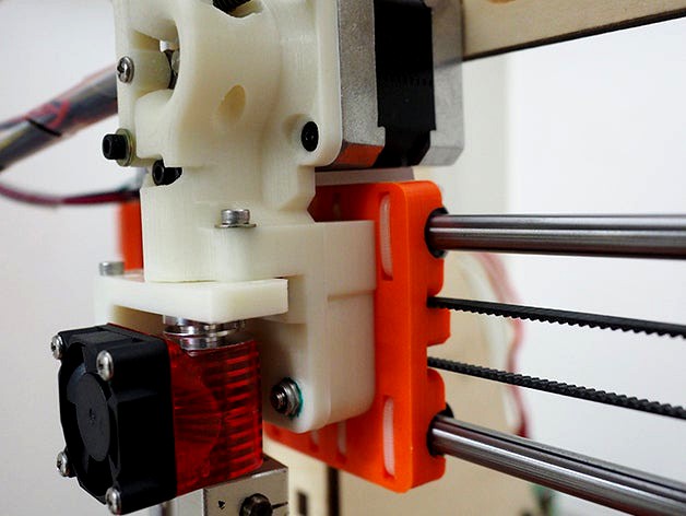
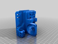
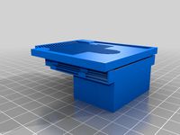
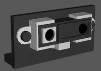
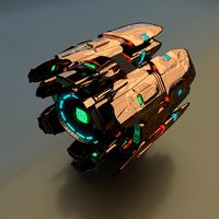
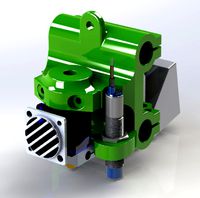
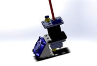
Unified Prusa i3 Extruder for Mk8 drive gear, e3d v6 hotend, and BLTouch sensor. by inornate
by Thingiverse
Last crawled date: 3 years ago
I remixed the great extruder design by coricoco (thing #755164) and applied some design improvement from Marck80's remix (thing #932386).
This design has numerous advantages.
The solid and unified design requires minimal assembly.
No Bowden.
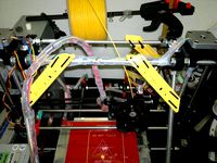
Minimal footprint, so it does not cannibalize printing volume.
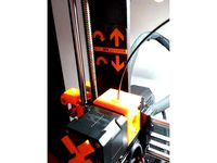
The center of weight is on the X axis.
Capable of Flexible filaments.
This design is backward compatible. You might able to use various accessories from the previous designs (#755164 and #932386).
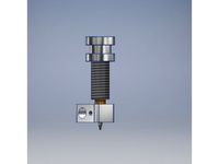
This extruder is for Mk8 drive gear (effective diameter 7mm) and an E3Dv6 nozzle.
Also, it equips BLTouch auto leveling sensor mount ( https://www.indiegogo.com/projects/bltouch-auto-leveling-sensor-for-3d-printers ).
Required additional parts and gears
PTFE tube (o.d 4mm / i.d 2mm)
M3*7mm countersunk bolts (x4)
M3*5mm bolts (x2)
M3*20mm bolt (x2)
M3*25mm bolt (x1)
M3*50mm bolts (x2)
M4*40mm bolts (x4)
M3 & M4 Nyloc nuts
Washers
Springs x2 (about 15mm)
3mm&4mm drills
M3 Tap
623 or 624 bearing 1ea
Mk8 drive gear
E3Dv6 hotend (or lite ver.)
NEMA17 & 31mm stepper motor.
(Optional) BLTouch sensor
Printing Instruction
I recommend using high infill rate (above 40%) and 3 perimeters. I used ABS but PLA probably works fine. Reorient parts if required.
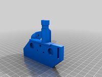
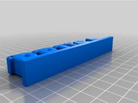
Print [Extruder_mk8]. It's designed to be printed without raft and supports, however, choose decent bed adhesion option if needed.
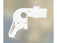
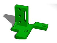
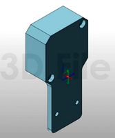
Print [Extruder_fixer]. If you want to use BLTouch sensor, print the _BLTouch ver. Otherwise, print the _normal version.
Print [Extruder_tensioner] for your bearing size.
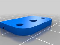
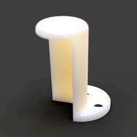
Print [Spacer] and [TubeClamp].
Assembly Instruction
For better vibration resistance. use Nyloc nuts for every possible place.
Remove the pre-designed supports.
Clean the holes using drills.
Tap two M3 threads at the center of the extruder.
Test mount an E3D nozzle. Cut the PTFE tube to be placed just below the drive gear.
Mount a stepper motor using M3*7mm countersunk bolts
Mount a bearing to the [Extruder_tensioner]. For 623 bearing, use M3x20mm bolt. For 624 bearing, use M4x25mm bolt. If you're using 624 bearing, place the bolt head toward the stepper.
Mount the [Extruder_tensioner] assembly to the extruder body. Use M3*25mm bolt and add some washers for clearance. Tightening the bolt is tricky here. Use a long-nose plier to fix a nut. Make sure the tensioner is moving freely.
Mount the Mk8 drive gear to the stepper.
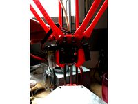
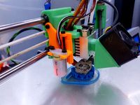
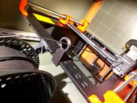
Using two M3*50mm bolts, springs, and nut, push the bearing against the drive gear. Refer the picture.
Place four M4 Nyloc nuts to the extruder body. Apply a drop of super glue to avoid falloff during assembly.
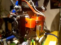
Using [Extruder_fixer] and two M3x20mm bolts, mount the E3Dv6 hotend.
If your hotend has PTFE tube clamp, just go to next step. Otherwise, clamp the PTFE tube using TubeClamp part & two M3*5mm bolts.
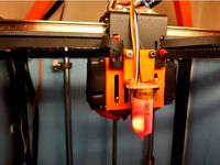
(Optional) Mount the BLTouch sensor. The X-offset between the nozzle and sensor probe is 23mm. Y-offset is zero. Z-offset is required to be calibrated for your parts.
Mount the extruder assembly to the carriage using four M4*40mm bolts. Sandwich [Spacer] between them.
If you have some rubbery material, place it between the stepper motor and carriage. This will greatly reduce the vibration during print.
This design has numerous advantages.
The solid and unified design requires minimal assembly.
No Bowden.
Minimal footprint, so it does not cannibalize printing volume.
The center of weight is on the X axis.
Capable of Flexible filaments.
This design is backward compatible. You might able to use various accessories from the previous designs (#755164 and #932386).
This extruder is for Mk8 drive gear (effective diameter 7mm) and an E3Dv6 nozzle.
Also, it equips BLTouch auto leveling sensor mount ( https://www.indiegogo.com/projects/bltouch-auto-leveling-sensor-for-3d-printers ).
Required additional parts and gears
PTFE tube (o.d 4mm / i.d 2mm)
M3*7mm countersunk bolts (x4)
M3*5mm bolts (x2)
M3*20mm bolt (x2)
M3*25mm bolt (x1)
M3*50mm bolts (x2)
M4*40mm bolts (x4)
M3 & M4 Nyloc nuts
Washers
Springs x2 (about 15mm)
3mm&4mm drills
M3 Tap
623 or 624 bearing 1ea
Mk8 drive gear
E3Dv6 hotend (or lite ver.)
NEMA17 & 31mm stepper motor.
(Optional) BLTouch sensor
Printing Instruction
I recommend using high infill rate (above 40%) and 3 perimeters. I used ABS but PLA probably works fine. Reorient parts if required.
Print [Extruder_mk8]. It's designed to be printed without raft and supports, however, choose decent bed adhesion option if needed.
Print [Extruder_fixer]. If you want to use BLTouch sensor, print the _BLTouch ver. Otherwise, print the _normal version.
Print [Extruder_tensioner] for your bearing size.
Print [Spacer] and [TubeClamp].
Assembly Instruction
For better vibration resistance. use Nyloc nuts for every possible place.
Remove the pre-designed supports.
Clean the holes using drills.
Tap two M3 threads at the center of the extruder.
Test mount an E3D nozzle. Cut the PTFE tube to be placed just below the drive gear.
Mount a stepper motor using M3*7mm countersunk bolts
Mount a bearing to the [Extruder_tensioner]. For 623 bearing, use M3x20mm bolt. For 624 bearing, use M4x25mm bolt. If you're using 624 bearing, place the bolt head toward the stepper.
Mount the [Extruder_tensioner] assembly to the extruder body. Use M3*25mm bolt and add some washers for clearance. Tightening the bolt is tricky here. Use a long-nose plier to fix a nut. Make sure the tensioner is moving freely.
Mount the Mk8 drive gear to the stepper.
Using two M3*50mm bolts, springs, and nut, push the bearing against the drive gear. Refer the picture.
Place four M4 Nyloc nuts to the extruder body. Apply a drop of super glue to avoid falloff during assembly.
Using [Extruder_fixer] and two M3x20mm bolts, mount the E3Dv6 hotend.
If your hotend has PTFE tube clamp, just go to next step. Otherwise, clamp the PTFE tube using TubeClamp part & two M3*5mm bolts.
(Optional) Mount the BLTouch sensor. The X-offset between the nozzle and sensor probe is 23mm. Y-offset is zero. Z-offset is required to be calibrated for your parts.
Mount the extruder assembly to the carriage using four M4*40mm bolts. Sandwich [Spacer] between them.
If you have some rubbery material, place it between the stepper motor and carriage. This will greatly reduce the vibration during print.
Similar models
thingiverse
free
7:32 Compact Geared Extruder Nema17 and 14 by ryannining
...haft bearing
1x 624 for idler.
1xm4 nut
to make tensior, i use steel from peg to clamphttps://www.youtube.com/watch?v=-7bpu9pbq18
thingiverse
free
Schematix: Dual Drive Extruder (Fits E3D v6) by Schematix
....d 4mm o.d
springs (some experimentation may be required) however i use the following:
wire diameter: 0.7mm x 6mm o.d x 18mm long
thingiverse
free

Tentacles Cooler for MK8 extruder adjustable mount
... mount to fit different hotend lengths.
thread m4 holes in fan mount, or drill it and use m4 nuts, or just use m3 bolts and nuts.
thingiverse
free

Dual stepper MK8 gear direct drive bowden extruder
...
2x m3 washer for holding the bearings in place
2x pneumatic push-in fittings with m5 threads for the bowden tube diameter in use
thingiverse
free

Alpha Direct Drive Extruder by engineglue
...upply list; this is a minimal design. you can use m4 bolts and nuts to mount it. it mounts to a standard aluminum mounting plate.
thingiverse
free

Prusa I3 Direct Drive Extruder 3mm by alphapilot
...aliexpress.com/item/mk7-bore-8mm-extruder-drive-gear-for-3mm-hobbed-gear-for-makerbot-reprap-mendel-high-quality/32462285369.html
thingiverse
free

Extruder Nema23 MK8 by fawan21
...cs
bolt jp m4 x 16, 1 pc
bolt jp m4 x 50, 4 pcs
bearing 624zz, 1 pc
hex nut m3, 1 pc
hex nut m4, pcs
https://youtu.be/44dng7swzc8
thingiverse
free

1.75mm Direct Drive Extruder by tosjduenfs
... to use ptfe tubing to guide filament to the extruder you can print the ptc (push-to-connect) holder for the top of the extruder.
thingiverse
free
Rackprint Bowden Extruder by Alex_RP
...x m3 screw ~20mm and nuts
2x m3 screw 15mm
bearing 608zz
mk8 drive gear
2x spring ~20mm with ~3mm inner diameter
thingiverse
free

Rusa bowden extruder gear by urusa
...tes the m5 bolts.
the shaft is fixed to the motor rotation.
secure the mk7 extrusion gear to the m5 bolts.
the gear ratio is 1/3.
Inornate
thingiverse
free

White Mage Minion by inornate
...inornate
thingiverse
white mage derived from "black mage minion from final fantasy xiv" by panini.
no need of support.
thingiverse
free

Prusa i3 Frame Fixing Mounts by inornate
...prusa i3 frame fixing mounts by inornate
thingiverse
immobilize your frame!
your printer will be rock solid after this mod.
thingiverse
free

Flying Spaghetti Monster (FSM) Emblem by inornate
...aghetti monster (fsm) emblem by inornate
thingiverse
it's a high-quality version of fsm emblem for your any purposes.
ramen!
thingiverse
free

KAIST character by inornate
...ch require lots of support) and another one is a flattened and lay downed model for 3d printing.
earphone winder version added.
thingiverse
free

E3D Hemera extruder indicator by inornate
...and it's good to rotate!
best print with two colors (filament change method).
working in action: https://youtu.be/c8hmqkz_fmc
thingiverse
free

BLTouch auto leveling sensor (dummy prop) by inornate
...ensor virtually in your design.
dimensions from https://www.indiegogo.com/projects/bltouch-auto-leveling-sensor-for-3d-printers#/
thingiverse
free

Printable tatting shuttle by inornate
...ts for the center column, which relieve the stress of the plate. also, there is "big" version for bigger tatting piece.
thingiverse
free

Auto bed leveling using piezo discs - Remixed by inornate
...r transfers the force to the piezo disc.
the original design was done by elenhinan, thing http://www.thingiverse.com/thing:707392
thingiverse
free

ImmersionRC rapidFIRE module door (cover) for FatShark goggles by inornate
...'t design this and all the rights are deserved by immersionrc.
not suitable for fdm printers.
recommend resin-based printing.
thingiverse
free

Kleenex Tissue Box Holder by inornate
...work with any tissue box with 11cm~12cm height. four pyramids inside the clip will hold the box tightly. it will never slip away.
Unified
3ddd
$1

Душевой Смеситель
...сэмплов всех a&d; материалов равно 1 для использования с unified sampling. для глобального изменения сэмплов в материалах можно воспользоваться...
3ddd
$1

Зеркало в санузел
...сэмплов всех a&d; материалов равно 1 для использования с unified sampling. для глобального изменения сэмплов в материалах можно воспользоваться...
3ddd
$1

Набор гостиничной мебели
...сэмплов всех a&d; материалов равно 1 для использования с unified sampling. для глобального изменения сэмплов в материалах можно воспользоваться...
3ddd
$1

Сушка для тарелок
...сэмплов всех a&d; материалов равно 1 для использования с unified sampling. для глобального изменения сэмплов в материалах можно воспользоваться...
3ddd
free

энергосберегающий контроллер "SALTO"
...сэмплов всех a&d; материалов равно 1 для использования с unified sampling. для глобального изменения сэмплов в материалах можно воспользоваться...
3d_export
$15

PKP Pecheneg
...pkp pecheneg 3dexport the unified russian pkp "pecheneg" (6541) 7.62 mm is widely known...
3d_export
$79

Female Muscular System
...female muscular system 3dexport this model is a unified muscle textured to a male 3d model, this includes...
3d_export
$15

Masculine Female
...masculine female 3dexport this model is a unified muscle textured to a male 3d model, this includes...
3ddd
$1

Диван "БОСТОН"
...сэмплов всех a&d; материалов равно 1 для использования с unified sampling. для глобального изменения сэмплов в материалах можно воспользоваться...
3ddd
$1

Стол на опоре Spartak-light с табуретами
...сэмплов всех a&d; материалов равно 1 для использования с unified sampling. для глобального изменения сэмплов в материалах можно воспользоваться...
Mk8
3d_export
$99

Mitsubishi Lancer Ralliart sedan 2004 3D Model
...lancer ralliart sedan 2004 3d model 3dexport mitsubishi ralliart mk8 2004 2005 4-door sedan saloon japan japanese eighth generation...
3d_ocean
$89

Mitsubishi Lancer Ralliart sedan 2004
...2004-2005 4-door eighth generation japan japanese mitsubishi mitsubishi ralliart mk8 ralliart saloon sedan the 3d model was created on...
thingiverse
free

MK8 by IsaiRochaSegura
...chasegura
thingiverse
in this thing i share a replace bar for mk8 extruder. i include the solidworks files for any modification.
thingiverse
free

MK8 Duct by ombranova
...mk8 duct by ombranova
thingiverse
duct for extruder mount mk8 on prusa i3
thingiverse
free

MK8 Flex Guide by loganjkd
...mk8 flex guide by loganjkd
thingiverse
just an inset for the mk8
thingiverse
free

MK7 / MK8 Mold by JMDesigns
...mk7 / mk8 mold by jmdesigns
thingiverse
mk7 / mk8 mold
thingiverse
free

Support extruder MK8 by rickshaolin
...support extruder mk8 by rickshaolin
thingiverse
support extruder mk8
thingiverse
free

MK8 Fan bracket by rocktang2003
...mk8 fan bracket by rocktang2003
thingiverse
mk8 fan bracket
thingiverse
free

HyperCube Mk8 mount by machala737
...hypercube mk8 mount by machala737
thingiverse
remix hypercube mk8 mount
thingiverse
free

mk8 fan holder by everythingother
...mk8 fan holder by everythingother
thingiverse
this is mk8 amazing fan holder
Bltouch
thingiverse
free
Support bltouch by TonyJ
...support bltouch by tonyj
thingiverse
support bltouch
thingiverse
free
BLTOUCH for MICRON3DP by lamerhouse
...bltouch for micron3dp by lamerhouse
thingiverse
bltouch for micron3dp
thingiverse
free
SapphirePro mount for Bltouch
...sapphirepro mount for bltouch
thingiverse
sapphirepro mount for bltouch
thingiverse
free
ender6 BLtouch by chimaer
...ender6 bltouch by chimaer
thingiverse
ender6 bltouch
this is an external bracket
thingiverse
free
BLTouch KP3s by 1devilman1
...bltouch kp3s by 1devilman1
thingiverse
bltouch mount for kingroon kp3s
thingiverse
free
Bltouch support adjustable
...bltouch support adjustable
thingiverse
adjustable support for bltouch, p3steel.
thingiverse
free
BMG NEREUS BLTOUCH
...bmg nereus bltouch
thingiverse
petg
m3 screws and nuts for the bltouch
thingiverse
free

BLTouch Bracket by tidh666
...bltouch bracket by tidh666
thingiverse
serves to attach the bltouch sensor to the extruders
thingiverse
free
bltouch mount by wars
...bltouch mount by wars
thingiverse
reinforced bracket for bltouch cooperates with high_clearance_cr10_oem_fang_mod
thingiverse
free

BLTouch Holder by Jonthan06
...bltouch holder by jonthan06
thingiverse
support bltouch pour wanhao d12
Hotend
thingiverse
free
hotend by fablab_lueneburg
...hotend by fablab_lueneburg
thingiverse
hotend model
thingiverse
free
Hotend for Graber
...hotend for graber
thingiverse
hotend complement pastes for graber printerhttps://youtu.be/0koxhnsuhdy
thingiverse
free
Hotend adapter by antaviana
...hotend adapter by antaviana
thingiverse
hotend adapter
thingiverse
free
hotend fan by mming1106
...hotend fan by mming1106
thingiverse
hotend fan
thingiverse
free

Hotend schema by ione
...hotend schema by ione
thingiverse
hotend project schema
thingiverse
free
Fabtotum XY Hotend holder for E3D Hotend
...s with integrated supports.
more for the project you can see here: https://kf-designs.com/2019/09/07/fabtotum-printer-conversion/
thingiverse
free
HotEnd Stand by onepointdiy
...tend, when you make your new hotend or repair your j-head or mg-plus hotend.
the hole of 16mm, please adjust using a reamer, etc.
thingiverse
free

fast magnetic hotend changer for Chimera Hotend by Draman
...chimera hotend !
and new basis (the hole from original is to small)
it is a remix form skimmy's fast magnetic hotend changer
thingiverse
free

Hotend Fan Adapter for MicroSwiss All Metal Hotend by jo_schi_man
...
thingiverse
little change for the hotend fan adapter to hold the microswiss all metal hotend (slightly longer and sharp edges).
thingiverse
free
Merlin Hotend by Alejanson
...merlin hotend by alejanson
thingiverse
this is a 1:1 drawing of the classic merlin hotend.
E3D
turbosquid
$23

E3D - Google Home
... 3d model e3d - google home for download as max, obj, and c4d on turbosquid: 3d models for games, architecture, videos. (1192509)
cg_studio
free

e3d model
...e3d model
cgstudio
- e 3d model, royalty free license available, instant download after purchase.
turbosquid
$2
Syringe C4D (E3D Ready)
...lty free 3d model syringe c4d (e3d ready) for download as c4d on turbosquid: 3d models for games, architecture, videos. (1336720)
turbosquid
$12
Microphone USB E3D and C4D
...ree 3d model microphone usb e3d & c4d for download as c4d on turbosquid: 3d models for games, architecture, videos. (1568216)
turbosquid
$29

E3D - OnePlus 6 Black
...model e3d - oneplus 6 black for download as max, obj, and c4d on turbosquid: 3d models for games, architecture, videos. (1358534)
turbosquid
$29

E3D - Motorola One 2018
...del e3d - motorola one 2018 for download as max, obj, and c4d on turbosquid: 3d models for games, architecture, videos. (1358533)
turbosquid
$29
E3D - Disney MagicBands 2
...l e3d - disney magicbands 2 for download as max, obj, and c4d on turbosquid: 3d models for games, architecture, videos. (1355515)
turbosquid
$29

E3D - Samsung Z4 Smartphone
...e3d - samsung z4 smartphone for download as max, obj, and c4d on turbosquid: 3d models for games, architecture, videos. (1182179)
turbosquid
$23

E3D - Razer Phone model
...del e3d - razer phone model for download as max, obj, and c4d on turbosquid: 3d models for games, architecture, videos. (1231207)
turbosquid
$23

E3D - Alcatel Idol 5
... model e3d - alcatel idol 5 for download as max, obj, and c4d on turbosquid: 3d models for games, architecture, videos. (1212799)
V6
3d_export
$100
v6 engine
...engine
3dexport
complete v6 engine modeled on solidworks 2017 along with .stl, .sldprt and .sldasm of all th parts and assembly.
3d_export
$10
V6 engine
... the first v6 engines were designed and produced independently by marmon motor car company, deutz gasmotoren fabrik and delahaye.
3d_export
$35
v6 engine
...s a complete model of a v6 engine containing over 400 components. you can contact me for a video of all the components assembling
3d_export
$10

v6 engine
...v6 engine
3dexport
turbosquid
$25

Bed1001-v6
... available on turbo squid, the world's leading provider of digital 3d models for visualization, films, television, and games.
turbosquid
$22
Chair2-v6
... available on turbo squid, the world's leading provider of digital 3d models for visualization, films, television, and games.
turbosquid
$20

V6.mb
... available on turbo squid, the world's leading provider of digital 3d models for visualization, films, television, and games.
3d_export
$20
V6 engine
...rovided in this package is all the parts in sldprt format and assembly in sldasm format. i can also convert the format on demand.
3ddd
$1
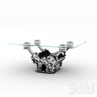
Стол V6
...6" в стиле дизельпанк изготовлен из блока двигателя, 4х поршней и 4х шатунов.
столешница изготовлена из стекла толщиной 8мм.
cg_studio
$199
V6 VVTi3d model
...v6 vvti3d model
cgstudio
.3ds - v6 vvti 3d model, royalty free license available, instant download after purchase.
I3
3d_export
$10
suv i3
...suv i3
3dexport
suv i3 2013 series
3d_ocean
$89
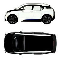
BMW i3 2012
...y, in real units of measurement, qualitatively and maximally close to the original. model formats: - *.max (3ds max 2008 scanl...
cg_studio
$99

BMW i3 20143d model
...
cgstudio
.3ds .c4d .fbx .lwo .max .obj - bmw i3 2014 3d model, royalty free license available, instant download after purchase.
cg_studio
$99

BMW i3 20123d model
...tudio
.3ds .c4d .fbx .lwo .max .mb .obj - bmw i3 2012 3d model, royalty free license available, instant download after purchase.
cg_studio
$99

BMW i3 20143d model
...tudio
.3ds .c4d .fbx .lwo .max .mb .obj - bmw i3 2014 3d model, royalty free license available, instant download after purchase.
humster3d
$75
3D model of BMW i3 2014
...
buy a detailed 3d model of bmw i3 2014 in various file formats. all our 3d models were created maximally close to the original.
humster3d
$40

3D model of Kitchen Set I3
...uy a detailed 3d model of kitchen set i3 in various file formats. all our 3d models were created maximally close to the original.
3d_ocean
$30
Kitchen set i3
...ensils oven plates shelves sink table ware
kitchen set i3 include 3d models: cooker, oven, sink, cupboards, table, chair, plates.
3d_ocean
$89

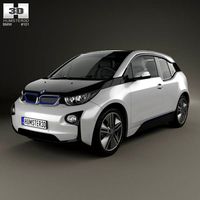
BMW i3 2014
...y, in real units of measurement, qualitatively and maximally close to the original. model formats: - *.max (3ds max 2008 scanl...
cg_studio
$99

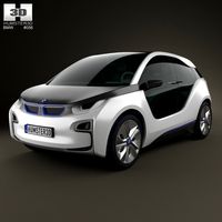
BMW i3 Concept 20113d model
...i3
.3ds .c4d .fbx .lwo .max .obj - bmw i3 concept 2011 3d model, royalty free license available, instant download after purchase.
Prusa
turbosquid
$2
Frame Filament Guide Clip-On for Prusa Mk3
...rame filament guide clip-on for prusa mk3 for download as stl on turbosquid: 3d models for games, architecture, videos. (1634730)
3d_export
free
prusa i3 mk3s laser mount for opt lasers
...to learn more about the blue laser technology that conceived the cutting and engraving laser heads from opt lasers, please visit:
turbosquid
free
Prusa small printer adapter holder
...er for download as ipt, skp, dwg, dxf, fbx, ige, obj, and stl on turbosquid: 3d models for games, architecture, videos. (1642936)
3d_export
$30

geisha by jonathan adler
...** i did a 3d printing test in the prusa software, you can find it among the attached images.<br>exchange:<br>.blend...
thingiverse
free

Prusa without Prusa (rc2) by madless
...prusa without prusa (rc2) by madless
thingiverse
just the main part of prusa rc2 faceshield, without writing.
enjoy :)
thingiverse
free
Prusa by acejbc
...prusa by acejbc
thingiverse
prusa knob info
m3 8mm screw
thingiverse
free
Prusa house
...prusa house
thingiverse
how prusa house could look like...
thingiverse
free

Prusa Mk2 "Fake Prusa" LCD cover by anraf1001
...r by anraf1001
thingiverse
version of prusa's lcd cover with "fake prusa" instead of "original prusa"
thingiverse
free
Prusa stabilizator by gutiueugen
...prusa stabilizator by gutiueugen
thingiverse
prusa stabilizator
thingiverse
free
Keychain Prusa by rbarbalho
...keychain prusa by rbarbalho
thingiverse
keychain with text prusa.
Sensor
3d_export
free

parking sensor
...parking sensor
3dexport
car parking sensor
turbosquid
$1
Sensor
... available on turbo squid, the world's leading provider of digital 3d models for visualization, films, television, and games.
3d_export
$5
Smoke sensor
...port
smoke sensor, can be an impressive element for your projects. easy to use, realistic image, low polygon, quality materials.
3d_export
$5
Air Quality Sensor v1
...air quality sensor v1
3dexport
air quality sensor v1
3d_export
$15
float sensor
...e up render. - all parts and materials are logically named. other formats ================= - collada (.dae) - autodesk fbx - obj
turbosquid
$26
Wind sensor C
...free 3d model wind sensor c for download as 3ds, obj, and fbx on turbosquid: 3d models for games, architecture, videos. (1328943)
turbosquid
$26
Wind sensor B
...free 3d model wind sensor b for download as 3ds, obj, and fbx on turbosquid: 3d models for games, architecture, videos. (1328168)
3d_export
$5
ultrasound sensor
...ivers convert ultrasound into electrical signals, and transceivers can both transmit and receive ultrasound. export in: -obj -fbx
3ddd
free
Вытяжка Shindo pallada sensor
... вытяжка
вытяжка shindo pallada sensor. в двух размерах - 600 и 900. текстуры в комплекте.
turbosquid
$52
Wind sensor A B C
...
royalty free 3d model wind sensor a b c for download as fbx on turbosquid: 3d models for games, architecture, videos. (1408406)
Drive
turbosquid
$90
Drive
...turbosquid
royalty free 3d model drive for download as blend on turbosquid: 3d models for games, architecture, videos. (1654393)
3d_export
$10

cycloidal drive
...cycloidal drive
3dexport
cycloidal drive
3d_ocean
$5
Flash Drive
...h drive included : – materials – scene ( lighs / room ) – .c4d + .obj for any questions please feel free to contact me thank you.
3d_ocean
$5

Usb drive
...s shaders and a lighting setup. it also has a small animation of it going in and out. i saved it out as both a .blend file and...
3d_ocean
$5

Pen Drive
...est computer drive game model good low poly new pen pen drive textured unwrapped uv very low poly
a very beautiful low poly model
3d_ocean
$10
External hard drive
... is a detailed model of a trekstor external hard drive. you can easily modify the label on the top. simply edit the text objects.
turbosquid
$60

Star Drive
...squid
royalty free 3d model star drive for download as blend on turbosquid: 3d models for games, architecture, videos. (1254314)
turbosquid
$50
Star Drive
...squid
royalty free 3d model star drive for download as blend on turbosquid: 3d models for games, architecture, videos. (1263524)
turbosquid
$45
Star Drive
...squid
royalty free 3d model star drive for download as blend on turbosquid: 3d models for games, architecture, videos. (1287060)
turbosquid
$40
Star Drive
...squid
royalty free 3d model star drive for download as blend on turbosquid: 3d models for games, architecture, videos. (1261902)
Extruder
3ddd
$1
Extruded Chair
...extruded chair
3ddd
extruded , tom dixon
inspired by tom dixon extruded chair
turbosquid
$15
Extruded Table
... extruded table for download as blend, dae, fbx, obj, and stl on turbosquid: 3d models for games, architecture, videos. (1634137)
turbosquid
$2
3D Printer Extruder
...d
royalty free 3d model 3d printer extruder for download as on turbosquid: 3d models for games, architecture, videos. (1537359)
turbosquid
$1
Zombie extruded text
...oyalty free 3d model zombie extruded text for download as obj on turbosquid: 3d models for games, architecture, videos. (1322198)
turbosquid
$4
Extruder conical screw
...el extruder conical screw for download as sldpr, ige, and stl on turbosquid: 3d models for games, architecture, videos. (1524433)
turbosquid
$50
3d PRINTER - Extruder
... available on turbo squid, the world's leading provider of digital 3d models for visualization, films, television, and games.
turbosquid
$15
Extruded Table 2
...xtruded table 2 for download as blend, dae, fbx, obj, and stl on turbosquid: 3d models for games, architecture, videos. (1621846)
turbosquid
$10
Maya Extrude Tool
... available on turbo squid, the world's leading provider of digital 3d models for visualization, films, television, and games.
3d_export
$5

world earth extrude map
...world earth extrude map
3dexport
3ddd
$1
Simply Elegant Extruded Tree Coffee Table Design
...ble by link studios. the silhouette of a tree is visible at one angle, extruded from the surface to create the support structure.
Gear
3d_ocean
$4
Gears
...gears
3docean
gear gears iron
4 different size of gears
3d_export
$5
gear
...gear
3dexport
gear
3d_export
free
Gears
...gears
3dexport
gears
3d_export
$5
gear
...gear
3dexport
a simple model of gear
3d_export
$5
gear
...gear
3dexport
gear for transmission , case machine
3d_ocean
$3
Gears
...nical parts process steampunk vehicle wheel work
10 different gear models volume 01-10 files: .3ds .c4d .obj note: you need vray
3d_ocean
$1

Spur Gear
...spur gear
3docean
decoration gear
a typical spur gear
3d_ocean
$4
Gear wheels
...gear wheels
3docean
engine engineering gear gears industry machinery mechanical toothwheel wheel
pair of gear wheels : animated.
turbosquid
$9
Gear
...gear
turbosquid
royalty free 3d model gear for download as on turbosquid: 3d models for games, architecture, videos. (1712328)
turbosquid
$2
Gears
...rs
turbosquid
royalty free 3d model gears for download as ma on turbosquid: 3d models for games, architecture, videos. (1166710)