GrabCAD
Uneven pendulums
by GrabCAD
Last crawled date: 1 year, 11 months ago
Made with Autodesk Inventor 2014 as a Dynamic simulation. The action is due to the gravitation force only.
There are two kinds of pendulums:
• Mathematical pendulum - a punctate mass suspended by an in-extensible thread, that has no weight
• Physical pendulum - any other (real) pendulum
The mathematical pendulum is characterized by:
1 / The length ratio is equal to the ratio pendulum oscillation periods at the power two (for instance, the period of an oscillation is tripled if the length is multiplied by 3 at the power 2)
2 / The oscillation period is independent of the hanging body mass and the body nature (isochronous)
3 / When the amplitude oscillation is small, the period does not depend on amplitude
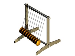
Here we have a set of ten physical pendulums with different lengths of the wire, which oscillate for 140 seconds without any friction. The wires are just like the bicycle spokes.
The moment of start (the zero seconds) is when all ten pendulums are at 20° to the left from the vertical. Even if the lengths of wires are here increased by 2 mm (from 142 to 160 mm), their oscillation periods do not grow strictly in arithmetical progression, because they are physical and not mathematical pendulums.
By working with Inventor you can use Output Grapher to export the velocity values corresponding to each pendulum on the same Excel file. The file is included here and it was created on a step basis of 0.01 seconds, so the file has 140 x 100 = 14000 lines.
If you study this file you can find two moments (marked in colors):
• Yellow: The moment when the velocities for all the ten pendulums are near zero at around the 68.10 seconds, but this is when they are directly opposed.
• Red: At the double time (136.20 seconds) you will find indeed the first moment when all the pendulums are in a position approximately similar with the start moment.
These „moments” are actually ranges, because they are extended on more than one single step. If you want to reduce the ranges you have to increase the similarity of the physical pendulums with mathematical pendulums. To do this you have to increase the length and the mass of the weight, as well as to reduce the start angle from 20° to at most 3°. Another way is to calculate or find the position of the center of gravity for every of the ten pendulums and to assign them values in an arithmetic progression.
Note that the start moment of the oscillation is at the 10 seconds in the movie. In other words, if you want to identify a precise step in the Excel file, you have to add 10 seconds when you look to the movie, so that 68.10 seconds is 78.10 seconds in the movie.
As usual, if you work with Inventor you will find all the .iam and .ipt files so you can download them to enter Environments / Dynamic simulation and see for yourself what's happening. You will have all the settings at your will, so you can change any settings you want. You can also modify the dimensions of parts - like the lengths of wires, for example.
Note: The idea for this stand comes from https://youtu.be/V87VXA6gPuE. If you manufacture the experimental stand using this data, then you will start the oscillation by using a bar to keep the pendulums aligned at the launching moment.
Enjoy!
There are two kinds of pendulums:
• Mathematical pendulum - a punctate mass suspended by an in-extensible thread, that has no weight
• Physical pendulum - any other (real) pendulum
The mathematical pendulum is characterized by:
1 / The length ratio is equal to the ratio pendulum oscillation periods at the power two (for instance, the period of an oscillation is tripled if the length is multiplied by 3 at the power 2)
2 / The oscillation period is independent of the hanging body mass and the body nature (isochronous)
3 / When the amplitude oscillation is small, the period does not depend on amplitude
Here we have a set of ten physical pendulums with different lengths of the wire, which oscillate for 140 seconds without any friction. The wires are just like the bicycle spokes.
The moment of start (the zero seconds) is when all ten pendulums are at 20° to the left from the vertical. Even if the lengths of wires are here increased by 2 mm (from 142 to 160 mm), their oscillation periods do not grow strictly in arithmetical progression, because they are physical and not mathematical pendulums.
By working with Inventor you can use Output Grapher to export the velocity values corresponding to each pendulum on the same Excel file. The file is included here and it was created on a step basis of 0.01 seconds, so the file has 140 x 100 = 14000 lines.
If you study this file you can find two moments (marked in colors):
• Yellow: The moment when the velocities for all the ten pendulums are near zero at around the 68.10 seconds, but this is when they are directly opposed.
• Red: At the double time (136.20 seconds) you will find indeed the first moment when all the pendulums are in a position approximately similar with the start moment.
These „moments” are actually ranges, because they are extended on more than one single step. If you want to reduce the ranges you have to increase the similarity of the physical pendulums with mathematical pendulums. To do this you have to increase the length and the mass of the weight, as well as to reduce the start angle from 20° to at most 3°. Another way is to calculate or find the position of the center of gravity for every of the ten pendulums and to assign them values in an arithmetic progression.
Note that the start moment of the oscillation is at the 10 seconds in the movie. In other words, if you want to identify a precise step in the Excel file, you have to add 10 seconds when you look to the movie, so that 68.10 seconds is 78.10 seconds in the movie.
As usual, if you work with Inventor you will find all the .iam and .ipt files so you can download them to enter Environments / Dynamic simulation and see for yourself what's happening. You will have all the settings at your will, so you can change any settings you want. You can also modify the dimensions of parts - like the lengths of wires, for example.
Note: The idea for this stand comes from https://youtu.be/V87VXA6gPuE. If you manufacture the experimental stand using this data, then you will start the oscillation by using a bar to keep the pendulums aligned at the launching moment.
Enjoy!
Similar models
cg_trader
$150

Variable g pendulum
...ot parallel to the gravitational field of the earth, only one component of the gravitational force acts on the pendulum movement.
thingiverse
free

Simple Pendulum by PocketLab
...on you can do in your classroom go here: https://www.thepocketlab.com/educators/lesson/3d-printed-pendulum-simple-harmonic-motion
grabcad
free

Lissajous Pendulum
...g the weight with a funnel filled with sand, the lissajous curve will appear on the horizontal plate as a streak of sand.
enjoy!
grabcad
free

Ansys regid dynamics analysis on pendulum mechanism
...period depends on the length of the pendulum and also to a slight degree on the amplitude, the width of the pendulum's swing.
cg_trader
$150

Mathematical pendulum
...nd a right swing is called the period. pendulum weight suspended pivot swing adobe challenge abstract elements science laboratory
cg_trader
$150

Mathematical pendulum
... motion is simple harmonic motion where θ0 is the amplitude of the oscillation (that is, the maximum angle between the rod of the
cg_trader
$150

Forced oscillations Pohls pendulum
... the free oscillation as well as the resonance curves of the forced oscillation for different damping values are to be determined
grabcad
free

Oscillation study
...oscillation study
grabcad
modeling of a mathematical pendulum with damped and harmonic oscillations
grabcad
free

flowmeter Endress Hauser
...hase, acting like a tuning
fork. the coriolis forces produced at the measuring tubes cause a phase shift in the tube oscillations
grabcad
free

Coupled pendulum (longitudinal)
...ant to see real collisions, you have to add some „2d contact” joints (between weights and between weights and the frame).
enjoy!
Pendulums
turbosquid
$10

Pendulum
... available on turbo squid, the world's leading provider of digital 3d models for visualization, films, television, and games.
turbosquid
$5

pendulum
... available on turbo squid, the world's leading provider of digital 3d models for visualization, films, television, and games.
3d_export
$5

pendulum of newton
...pendulum of newton
3dexport
newton's pendulum is made with respect to proportions and dimensions.
turbosquid
$20

pendulum clock
...uid
royalty free 3d model pendulum clock for download as c4d on turbosquid: 3d models for games, architecture, videos. (1489452)
turbosquid
$19

Pendulum trainer
...3d model pendulum trainer for download as , fbx, stl, and obj on turbosquid: 3d models for games, architecture, videos. (1684795)
turbosquid
$10

Foucault pendulum
...odel foucault pendulum for download as 3ds, max, obj, and fbx on turbosquid: 3d models for games, architecture, videos. (1441097)
turbosquid
$5

pendulum clock
... available on turbo squid, the world's leading provider of digital 3d models for visualization, films, television, and games.
design_connected
free

Pendulum Wall Mirror
...pendulum wall mirror
designconnected
free 3d model of pendulum wall mirror by cb2 designed by mermelada estudio.
3d_export
$65

big pendulum
...big pendulum
3dexport
simple rendering of the scene file
3d_ocean
$15

Pendulum Clock Kit
...endulum clock kit with a real clock system inside that you can control. the kit/rig is fully functional and controlled by xpresso
Uneven
vizpark
$5

Large Uneven
...neven is a set of 3d brick textures for modern buildings, including mulit-textures and 4k tileable textures with material layers.
cg_studio
$40

Uneven bars3d model
...rs3d model
cgstudio
.3ds .c4d .dxf .obj - uneven bars 3d model, royalty free license available, instant download after purchase.
turbosquid
$33

Uneven Road Sign
...e 3d model uneven road sign for download as 3ds, max, and obj on turbosquid: 3d models for games, architecture, videos. (1303384)
3d_export
$40

Uneven bars 3D Model
...ner horse parallel wall bars gym fitness sport equipment horizontal bar olimpic apparatus
uneven bars 3d model braz 8809 3dexport
cg_studio
$35

Uneven Road Sign3d model
...model
cgstudio
.3ds .max .obj .wrl - uneven road sign 3d model, royalty free license available, instant download after purchase.
3d_export
$25

Uneven Road Sign 3D Model
...t pedestrian urban city rural street highway roadway carriageway motorway town
uneven road sign 3d model plutonius 16962 3dexport
turbosquid
$30

wire fence for your location. fence includes armature, good for uneven ground. wire - transperense texture
...neven ground. wire - transperense texture for download as fbx on turbosquid: 3d models for games, architecture, videos. (1439298)
3d_export
$5

Triple bars
...triple bars for outdoor training/gymnastics. suitable for push-ups on uneven ...
3d_export
$29

3d Terrain Eroded 3D Model
...3d model land elevation soil erosion surface terrestrial rocks uneven 3d terrain eroded 3d model rmodeler 37767...
3d_export
$29

3d Terrain IceBerg 3D Model
...3d model land elevation soil erosion surface terrestrial rocks uneven ice 3d terrain iceberg 3d model rmodeler 37782...