Thingiverse
Ultracapacitor Driven, Dual Pulse Spot Welder, a Novel Iteration by wubwub89
by Thingiverse
Last crawled date: 3 years, 1 month ago
UPDATE (consolidated): Hi everyone. I have yet to find time for a video, mostly due to life pressures, etc, I have zero free time for anything that isn't paying. Please, as I stated in multiple places of this post, you must pay close attention to your primary resistances! Very small bits of resistance accumulating will negatively affect the operation of your welder. I have had more people write me saying the design doesn't work, and they include a picture of a total rats nest using 12 gauge wire. It will never, aside from elevated voltages, work right without really low sub-ohm resistances across the machine's primary circuits. If you have any questions, please read through the guide again before you write me. If you send me a message asking about something that is clearly specified in the guide, I may not be polite. If you have questions about something that is NOT specified in the guide, by all means feel free to write me or comment.
I do not plan to change this design at this time, however, in the near future I MIGHT switch the unit over to a toroid transformer on a 2x15v secondary in parallel and down-regulated for a big boost in charging current. At this time though, I am happy with the conversion efficiency of the large switched supply (it's really just a lightly modded laptop charger), and I am happy with the dwell time between firing, usually around 1-1.5 seconds depending on voltage used.
I have been using the welder consistently in building my own cell packs of all shapes and sizes, along with some other weird spot welding, like ground strapping on projects with metal cases. Everything is working great and consistently without any failures (exception being one full blow-out on an aluminum case cell, my fault for even trying a resistive weld on that!) at about 7500+ individual welds (I don't remember what the actual counter reads exactly).
I have had a few cell packs with mild issues, but not due to the welder. Apparently I picked up a batch of "pure nickel" tabs that were just nickel alloy coated really high iron content steel, and tons of them corroded to hell. I checked, and sure enough, tons of sparks coming from that batch of the grinder wheel. Some of the China direct sellers on various sites will sub in crap parts because they either don't know because they're just a salesman pushing widgets, or don't care. It's probably both, but regardless of all that make sure you check your source for nickel tabs.
UPDATE 2/2/18: I am having some hardware trouble with my camera recording in HD that will hopefully be solved in the next 30 days. I have gotten a few messages about my design not working, well, then you built it incorrectly or your components are out of spec! It's critical to minimize the primary circuit resistance properly! Please note, this is a critical engineering spec design with very little room for error or changes. Just using crimped lugs over soldered lugs may create too much resistance, circumstantially, and you MUST BE USING 4/0 GAUGE PRIMARIES OR LARGER, PERIOD [Edit: To clarify, I am saying this just to make sure anyone who builds the unit with a long primary circuit run doesn't encounter resistance issues]. I have NO trouble creating strong, deep coalescence through multiple boundary layers at low duty. IF you are getting blowouts, turn your primary pulse time and/or voltage down! Once again, this design does not allow for much error, including capacitor/bank quality from previous use and abuse.
UPDATE: After some more testing and production applications, it's working great for certain. However, I am struggling with some certain metals due to their resistance, notably copper and aluminum. I actually blew a hole through the casing of an aluminum LFP battery! (Oops, tossed it in a bag, then an empty paint can, and in the backyard to be safe, it's not reacting, if it was Li-Ion or it would have started thermal runaway and out-gassing potentially). That being said, it's demonstrably safe to use on steel casings as long as you don't lose the reigns on the pulse width and voltage. After investigating later on (when ambient temps were below 40 deg F), approximately a 0.5mm hole was found in the casing.
Hey everyone!
Firstly, This post is a work in progress! While the device is constructed, thoroughly tested, and working great, I will update and expand upon this post over the next month when I have time. Please like and collect to follow! I will be providing a very clear and advanced schematic for the electronics in this configuration. How you choose to build your enclosure and power supplies is totally up to you, but I will show you how to build and operate this type of unit safely. Again, this post will be reformatted, edited, and expanded over the next month. There will also be a detailed YouTube video regarding this methodology. Thank you!
This unit was designed and built by myself, for the purpose of spot welding battery tabs, spot welding small metallic projects, and generally, for providing very large amounts of current in a short period of time when needed.
This product's design is protected under Creative Commons Attribution, please give credit where credit is due!
DISCLAIMER and WARNING
This device utilizes both line AC voltage and extremely dense energy storage through the capacitor bank. AC 85v+ (probably less under the right conditions) with a big current supply is LETHAL when a human being acts as a ground path for the current available. Do not EVER, EVER touch, dismantle, assemble, test, look funny at it, or otherwise work with line voltage unless you know what you are doing! Seriously! The capacitor bank presents a very real, but different threat. The capacitor bank builds a reasonably safe DC voltage current source, which DC voltages below 24 volts can be considered safe, there are still some serious consequences to mishandling. DEAD SHORTS ACROSS HIGH-DENSITY ELDC UNITS WILL CAUSE A FIRE, EXPLOSION, SEVERE PERSONAL INJURY AND PROPERTY LOSS! Seriously, you do not want to dead short one of these units! ELDC shorts will vaporize box wrenches, destroy low impedance circuits, raise your car payment, and make your wife leave you! All kidding aside, please be careful when handing high-current devices, make sure you understand how to prevent traces from forming where they shouldn't, and avoid improperly constructed conductive parts, including wiring, IC's, anything that has a low electrical resistance is potentially an exploding fireball with shrapnel when working with super-high current devices.
So, now that my readers know they can accidentally kill themselves or lose everything in the process of building this device, let's get on with it!
ABSTRACT
The purpose of this article is to define the systems and subsystems of the aforementioned device and their working principles in detail, along with providing a clear, informative, and confusion-free schematic of the system and its subsystems. We will also be discussing material science involving spot-welding with this type of device. This document was written by an engineer, from the perspective of a DIY need to weld battery tabs and small metallic objects that are sensitive to heat. The author is not a professional welder. The writer was simply frustrated with the poor write-ups found on the web about these devices and did not approve of their safety or design effectiveness.
HOW IT WORKS
In principle, this device will adjoin two metallic objects together without the introduction of material (such as a welding rod etc), and generally, without the use of flux. In the case of welding battery tabs, the current can be passed through the tab, into the substrate, back out through the substrate, and back into the tab, in a closed loop, or it can be passed through the tab, and into the substrate. Of course, the polarity can be reversed by changing the probe location and orientation. The results of either method in either polarity configuration will vary greatly based on the resistance of the tab used, the resistance of the target substrate, in addition to overall performance attributable to the overall resistance of the devices current path, along with the ESR of the capacitor. Tab material types and construction will greatly affect the welding procedure, as the current path will differ between different types and methods employed. It's important to familiarize yourself with the type of materials you will be welding together, generally, nickel and steel are my primary targets. Other metals will require more voltage and a longer pulse time in many cases, but this requires further investigation on my part.
WHAT'S IT MADE OF?
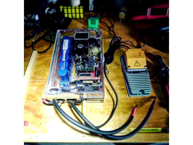
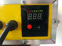
This device has a 5.1A digitally controlled and selectable constant voltage/current supply that controls the UC(Ultracapacitor) bank primary voltage, a microcontroller that controls the ON/OFF pulse time for both a small pulse to 'preheat' the materials and build an (ideally) gapless current path, then a larger pulse to complete the weld. Current paths with gaps will cause material breakdown and substrate erosion, which usually occurs when there is a loud pop, and very small pieces of molten metal go flying. In parallel with the primary welding circuit, there is a switchable 5-ohm resistor array (two 100w, 10-ohm resistors in parallel) with thermal insulation active cooling. The entire device is powered by a salvaged and reconfigured 19.5v+ laptop power supply, with each component individually voltage regulated and monitored as follows: the microcontroller and MOSFET array controller is powered by a dedicated L7812cv (12v+) regulator circuit, and the case cooling fan is regulated down to 9.5v+ with a variable CV regulator. Also, on the front-right of the device, you may notice a LED cluster, along with a LED light bar labeled 'Problem', both of these operate in parallel with the primary circuit, but they vary in how they are hooked up, we'll go over the data acquisition later on.
All of the wires in this unit is stranded 20, 18, 16, 12, 8, 6, or 4/0 AWG wire, with PVC or Silicone insulation. All of the high-current lugs are soldered instead of crimped. This is a personal preference, and since the device is to regarded as immobile and we're not expecting to experience multiple G's of vibrations, also, our high current flow will be well below the time needed to get the joints flowing again. This comes from professional knowledge and experience, where as long as the thermal loss from resistance remains lower than the thermal dissipation, to keep it simple, this device will not heat up terminals fast or high enough. Also, we don't want to worry about moisture oxidizing our copper wire, and potentially causing a complete or partial break down the line, as a free-swinging wire ready to carry up to 1400 amps is a terrible situation (See the section about exploding fireballs). We want to build a device that will, optimistically, have properly designed subsystem failure points that will prevent a catastrophic failure. Just about everything besides the primary circuit is fused, just in case of a short. The dissipation of the UC bank through a small gauge wire will almost instantly start a fire. ( I don't take this type of energy storage lightly, and neither should you!)
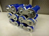
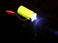
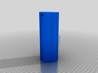
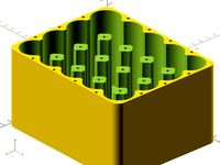
In my application, the Maxwell 58F UC(lovingly nicknamed, FireBoom9000) was chosen due to its low ESR (approximately 0.22mΩ), consisting of six 2.7v 500F supercapacitors placed in series on a protection board (which prevents overcharging, promotes voltage potential balance, and hopefully, reverse voltage spikes) and allows for a peak storage voltage of 16.2v, which we will never reach due to both energy requirements, and the 14v limitation of the TVS diode on the MOSFET array (more on that later). Also, the Maxwell 58F unit comes in this nicely packaged blue/gray ABS case for safety. Other types of storage could have been chosen, but I preferred this unit for its size and electrical characteristics. It's entirely unnecessary to use 6 3000F BoostCaps or something equally ridiculous in size. At about 12v, with a 25ms primary pulse, and a 15% short pulse (15% of 25ms, variable on the controller), we get a voltage drop of around 0.43v per firing. With the 5.1A supply set to 4A @ 12v, it takes about 1.5-2 seconds to get back to 12v in the UC bank. I finished my first 18650 Li-Ion 4s1p pack in about 20 minutes, WITH a BMS, without any bad welds.
Now, let's talk about the pulse control unit. When I started this endeavor, I wanted to build my own, write my own board files in Eagle CAD, send them out to one of the manufacturers, wait 30-60 days for my professional 4 layer boards to come back to me, write the software for an ATMEL 348p, prototype, break it, rinse and repeat. Then I found a wonderful source for a unit that was already produced, one with almost the exact specification I came up with (in my head) for this device. I decided that it was in my best interests and time conservation to purchase a manufactured unit from http://malectrics.eu , sold by Marc Shoenfleiesh for around $105USD (Shipped to Chicago). After talking with Marc through a few emails, we both were in agreeance to the function of this unit utilizing a UC bank in place of a lead-acid battery without trouble (He is a nice guy, very polite and helpful, I recommend his products). I also purchased his preassembled welding probes since they were around the same price to build them here, they're very nice. The control unit is powered by an external L7812cv without a common line attached, utilizing the module primary common for that circuit. This unit utilizes eight IRFB7430 MOSFET IC's in parallel to manage the current pulses. (Datasheet here: https://www.infineon.com/dgdl/irfb7430pbf.pdf?fileId=5546d462533600a4015356169bcd1e53) for current switching. This array, when closed, provides around 150 ohms resistance, allowing a handful of my subsystems to function in their own unique ways depending on their placement on the common bus. In my design, there are two common busses, one is not switched, the other is 150 ohm to the primary circuit when MOSFET array is in an 'open' state. The unit also includes a small OLED screen and a rotary encoder for control selection. There is also an 'Auto-pulse' function, but I will not use it with this device, ever. I utilize a (very obnoxious and unnecessarily large, thanks, Amazon Prime) footswitch as a trigger for this device. It's removable and uses a TS 1/4" bulkhead on the front of the case.
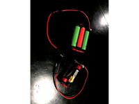
The outboard assembly includes the welding probes themselves, which are 6 gauge wire, terminated to thick copper electrodes cut to points. They work great, you can even see them dance from the current flow!
This one is important, to protect EVERYTHING from flyback current, I built a rather beefy TVS diode array. That's the orange shrink-wrapped guy labeled "Anti-Death Diode Array" on the two current bulkheads. This is a reverse facing diode that will allow inductive current to pass backward at the head of the circuit after the MOSFET array closes, causing an extreme reversal of current. Think of it as analogous to "water hammer" in the plumbing of your home; when you turn off the water flow rapidly, you hear a bang in the wall. This is the tendency of the water to try to keep flowing, attempt to compress, and immediately flow backward, causing cavitation in the pipes. When that vacuum bubble collapses, we hear that bang, at risk of gross oversimplification. By placing our very large diode array in this position, we are protecting all of our circuitry from flyback current by allowing this very strong inductive pressure to "flyback" from one probe to the other. The specifications of this unit will be listed later on.
On to the boring stuff. However, it's still fairly important.
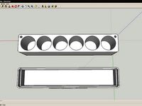
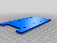
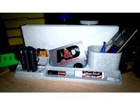
The case is made from two acrylic drawer organizers that can be found on Amazon Prime, I cemented a 12" acrylic hinge, and an acrylic latch onto these, and made a decent, non-conductive case for pretty cheap. Both the primary cc/cv unit and the pulse control unit are on custom cut nylon standoffs from the top of the case. These are secured with vanadium steel M3 cap-heads of varying length, which long enough to provide a secure hold to the case.
Now, we're going to talk about an extremely sensitive subject for myself; glue. I don't like glue. Glue doesn't like me. It's a necessary evil in budget assemblies and time constraints. There are only two types of adhesives used in this entire project; methyl ethyl ketone (MEK) cement, and high-temperature hot glue. Both are entirely non-conductive and cheap. MEK cement is a solvent cement designed for plastics, it works extremely well at binding acrylic, among a few other things. It is very tough and almost entirely rigid after curing, too. This was utilized for all of the plastic to plastic bonds in this project. Hot glue was used for all of the wiring positionings at the edges on the case, some added protection in certain areas against catastrophic shorts, and for a few of the more temporary mountings of components. I don't want to permanently cement a power supply in place to have it fail and need replacing. You may also note that I stayed away from silicone based products. I do not always approve of room temperature vulcanizing rubber for use in electrical projects, due to the insulative variance that seems to occur with air bubbles within the RTV bead. Unless it needs to be permanent for certain, and you're pressing the parts together firmly (e.g., hand-tightening a water pump while the RTV starts to vulcanize) I do not recommend a silicone, and for this project, absolutely no silicone (that does not include silicone wiring insulation, different process).
That's all for now, I will update with a complete electrical schematic and a detailed video mirroring this insight when I get around to it.
Thanks for reading!
-Alex
I do not plan to change this design at this time, however, in the near future I MIGHT switch the unit over to a toroid transformer on a 2x15v secondary in parallel and down-regulated for a big boost in charging current. At this time though, I am happy with the conversion efficiency of the large switched supply (it's really just a lightly modded laptop charger), and I am happy with the dwell time between firing, usually around 1-1.5 seconds depending on voltage used.
I have been using the welder consistently in building my own cell packs of all shapes and sizes, along with some other weird spot welding, like ground strapping on projects with metal cases. Everything is working great and consistently without any failures (exception being one full blow-out on an aluminum case cell, my fault for even trying a resistive weld on that!) at about 7500+ individual welds (I don't remember what the actual counter reads exactly).
I have had a few cell packs with mild issues, but not due to the welder. Apparently I picked up a batch of "pure nickel" tabs that were just nickel alloy coated really high iron content steel, and tons of them corroded to hell. I checked, and sure enough, tons of sparks coming from that batch of the grinder wheel. Some of the China direct sellers on various sites will sub in crap parts because they either don't know because they're just a salesman pushing widgets, or don't care. It's probably both, but regardless of all that make sure you check your source for nickel tabs.
UPDATE 2/2/18: I am having some hardware trouble with my camera recording in HD that will hopefully be solved in the next 30 days. I have gotten a few messages about my design not working, well, then you built it incorrectly or your components are out of spec! It's critical to minimize the primary circuit resistance properly! Please note, this is a critical engineering spec design with very little room for error or changes. Just using crimped lugs over soldered lugs may create too much resistance, circumstantially, and you MUST BE USING 4/0 GAUGE PRIMARIES OR LARGER, PERIOD [Edit: To clarify, I am saying this just to make sure anyone who builds the unit with a long primary circuit run doesn't encounter resistance issues]. I have NO trouble creating strong, deep coalescence through multiple boundary layers at low duty. IF you are getting blowouts, turn your primary pulse time and/or voltage down! Once again, this design does not allow for much error, including capacitor/bank quality from previous use and abuse.
UPDATE: After some more testing and production applications, it's working great for certain. However, I am struggling with some certain metals due to their resistance, notably copper and aluminum. I actually blew a hole through the casing of an aluminum LFP battery! (Oops, tossed it in a bag, then an empty paint can, and in the backyard to be safe, it's not reacting, if it was Li-Ion or it would have started thermal runaway and out-gassing potentially). That being said, it's demonstrably safe to use on steel casings as long as you don't lose the reigns on the pulse width and voltage. After investigating later on (when ambient temps were below 40 deg F), approximately a 0.5mm hole was found in the casing.
Hey everyone!
Firstly, This post is a work in progress! While the device is constructed, thoroughly tested, and working great, I will update and expand upon this post over the next month when I have time. Please like and collect to follow! I will be providing a very clear and advanced schematic for the electronics in this configuration. How you choose to build your enclosure and power supplies is totally up to you, but I will show you how to build and operate this type of unit safely. Again, this post will be reformatted, edited, and expanded over the next month. There will also be a detailed YouTube video regarding this methodology. Thank you!
This unit was designed and built by myself, for the purpose of spot welding battery tabs, spot welding small metallic projects, and generally, for providing very large amounts of current in a short period of time when needed.
This product's design is protected under Creative Commons Attribution, please give credit where credit is due!
DISCLAIMER and WARNING
This device utilizes both line AC voltage and extremely dense energy storage through the capacitor bank. AC 85v+ (probably less under the right conditions) with a big current supply is LETHAL when a human being acts as a ground path for the current available. Do not EVER, EVER touch, dismantle, assemble, test, look funny at it, or otherwise work with line voltage unless you know what you are doing! Seriously! The capacitor bank presents a very real, but different threat. The capacitor bank builds a reasonably safe DC voltage current source, which DC voltages below 24 volts can be considered safe, there are still some serious consequences to mishandling. DEAD SHORTS ACROSS HIGH-DENSITY ELDC UNITS WILL CAUSE A FIRE, EXPLOSION, SEVERE PERSONAL INJURY AND PROPERTY LOSS! Seriously, you do not want to dead short one of these units! ELDC shorts will vaporize box wrenches, destroy low impedance circuits, raise your car payment, and make your wife leave you! All kidding aside, please be careful when handing high-current devices, make sure you understand how to prevent traces from forming where they shouldn't, and avoid improperly constructed conductive parts, including wiring, IC's, anything that has a low electrical resistance is potentially an exploding fireball with shrapnel when working with super-high current devices.
So, now that my readers know they can accidentally kill themselves or lose everything in the process of building this device, let's get on with it!
ABSTRACT
The purpose of this article is to define the systems and subsystems of the aforementioned device and their working principles in detail, along with providing a clear, informative, and confusion-free schematic of the system and its subsystems. We will also be discussing material science involving spot-welding with this type of device. This document was written by an engineer, from the perspective of a DIY need to weld battery tabs and small metallic objects that are sensitive to heat. The author is not a professional welder. The writer was simply frustrated with the poor write-ups found on the web about these devices and did not approve of their safety or design effectiveness.
HOW IT WORKS
In principle, this device will adjoin two metallic objects together without the introduction of material (such as a welding rod etc), and generally, without the use of flux. In the case of welding battery tabs, the current can be passed through the tab, into the substrate, back out through the substrate, and back into the tab, in a closed loop, or it can be passed through the tab, and into the substrate. Of course, the polarity can be reversed by changing the probe location and orientation. The results of either method in either polarity configuration will vary greatly based on the resistance of the tab used, the resistance of the target substrate, in addition to overall performance attributable to the overall resistance of the devices current path, along with the ESR of the capacitor. Tab material types and construction will greatly affect the welding procedure, as the current path will differ between different types and methods employed. It's important to familiarize yourself with the type of materials you will be welding together, generally, nickel and steel are my primary targets. Other metals will require more voltage and a longer pulse time in many cases, but this requires further investigation on my part.
WHAT'S IT MADE OF?
This device has a 5.1A digitally controlled and selectable constant voltage/current supply that controls the UC(Ultracapacitor) bank primary voltage, a microcontroller that controls the ON/OFF pulse time for both a small pulse to 'preheat' the materials and build an (ideally) gapless current path, then a larger pulse to complete the weld. Current paths with gaps will cause material breakdown and substrate erosion, which usually occurs when there is a loud pop, and very small pieces of molten metal go flying. In parallel with the primary welding circuit, there is a switchable 5-ohm resistor array (two 100w, 10-ohm resistors in parallel) with thermal insulation active cooling. The entire device is powered by a salvaged and reconfigured 19.5v+ laptop power supply, with each component individually voltage regulated and monitored as follows: the microcontroller and MOSFET array controller is powered by a dedicated L7812cv (12v+) regulator circuit, and the case cooling fan is regulated down to 9.5v+ with a variable CV regulator. Also, on the front-right of the device, you may notice a LED cluster, along with a LED light bar labeled 'Problem', both of these operate in parallel with the primary circuit, but they vary in how they are hooked up, we'll go over the data acquisition later on.
All of the wires in this unit is stranded 20, 18, 16, 12, 8, 6, or 4/0 AWG wire, with PVC or Silicone insulation. All of the high-current lugs are soldered instead of crimped. This is a personal preference, and since the device is to regarded as immobile and we're not expecting to experience multiple G's of vibrations, also, our high current flow will be well below the time needed to get the joints flowing again. This comes from professional knowledge and experience, where as long as the thermal loss from resistance remains lower than the thermal dissipation, to keep it simple, this device will not heat up terminals fast or high enough. Also, we don't want to worry about moisture oxidizing our copper wire, and potentially causing a complete or partial break down the line, as a free-swinging wire ready to carry up to 1400 amps is a terrible situation (See the section about exploding fireballs). We want to build a device that will, optimistically, have properly designed subsystem failure points that will prevent a catastrophic failure. Just about everything besides the primary circuit is fused, just in case of a short. The dissipation of the UC bank through a small gauge wire will almost instantly start a fire. ( I don't take this type of energy storage lightly, and neither should you!)
In my application, the Maxwell 58F UC(lovingly nicknamed, FireBoom9000) was chosen due to its low ESR (approximately 0.22mΩ), consisting of six 2.7v 500F supercapacitors placed in series on a protection board (which prevents overcharging, promotes voltage potential balance, and hopefully, reverse voltage spikes) and allows for a peak storage voltage of 16.2v, which we will never reach due to both energy requirements, and the 14v limitation of the TVS diode on the MOSFET array (more on that later). Also, the Maxwell 58F unit comes in this nicely packaged blue/gray ABS case for safety. Other types of storage could have been chosen, but I preferred this unit for its size and electrical characteristics. It's entirely unnecessary to use 6 3000F BoostCaps or something equally ridiculous in size. At about 12v, with a 25ms primary pulse, and a 15% short pulse (15% of 25ms, variable on the controller), we get a voltage drop of around 0.43v per firing. With the 5.1A supply set to 4A @ 12v, it takes about 1.5-2 seconds to get back to 12v in the UC bank. I finished my first 18650 Li-Ion 4s1p pack in about 20 minutes, WITH a BMS, without any bad welds.
Now, let's talk about the pulse control unit. When I started this endeavor, I wanted to build my own, write my own board files in Eagle CAD, send them out to one of the manufacturers, wait 30-60 days for my professional 4 layer boards to come back to me, write the software for an ATMEL 348p, prototype, break it, rinse and repeat. Then I found a wonderful source for a unit that was already produced, one with almost the exact specification I came up with (in my head) for this device. I decided that it was in my best interests and time conservation to purchase a manufactured unit from http://malectrics.eu , sold by Marc Shoenfleiesh for around $105USD (Shipped to Chicago). After talking with Marc through a few emails, we both were in agreeance to the function of this unit utilizing a UC bank in place of a lead-acid battery without trouble (He is a nice guy, very polite and helpful, I recommend his products). I also purchased his preassembled welding probes since they were around the same price to build them here, they're very nice. The control unit is powered by an external L7812cv without a common line attached, utilizing the module primary common for that circuit. This unit utilizes eight IRFB7430 MOSFET IC's in parallel to manage the current pulses. (Datasheet here: https://www.infineon.com/dgdl/irfb7430pbf.pdf?fileId=5546d462533600a4015356169bcd1e53) for current switching. This array, when closed, provides around 150 ohms resistance, allowing a handful of my subsystems to function in their own unique ways depending on their placement on the common bus. In my design, there are two common busses, one is not switched, the other is 150 ohm to the primary circuit when MOSFET array is in an 'open' state. The unit also includes a small OLED screen and a rotary encoder for control selection. There is also an 'Auto-pulse' function, but I will not use it with this device, ever. I utilize a (very obnoxious and unnecessarily large, thanks, Amazon Prime) footswitch as a trigger for this device. It's removable and uses a TS 1/4" bulkhead on the front of the case.
The outboard assembly includes the welding probes themselves, which are 6 gauge wire, terminated to thick copper electrodes cut to points. They work great, you can even see them dance from the current flow!
This one is important, to protect EVERYTHING from flyback current, I built a rather beefy TVS diode array. That's the orange shrink-wrapped guy labeled "Anti-Death Diode Array" on the two current bulkheads. This is a reverse facing diode that will allow inductive current to pass backward at the head of the circuit after the MOSFET array closes, causing an extreme reversal of current. Think of it as analogous to "water hammer" in the plumbing of your home; when you turn off the water flow rapidly, you hear a bang in the wall. This is the tendency of the water to try to keep flowing, attempt to compress, and immediately flow backward, causing cavitation in the pipes. When that vacuum bubble collapses, we hear that bang, at risk of gross oversimplification. By placing our very large diode array in this position, we are protecting all of our circuitry from flyback current by allowing this very strong inductive pressure to "flyback" from one probe to the other. The specifications of this unit will be listed later on.
On to the boring stuff. However, it's still fairly important.
The case is made from two acrylic drawer organizers that can be found on Amazon Prime, I cemented a 12" acrylic hinge, and an acrylic latch onto these, and made a decent, non-conductive case for pretty cheap. Both the primary cc/cv unit and the pulse control unit are on custom cut nylon standoffs from the top of the case. These are secured with vanadium steel M3 cap-heads of varying length, which long enough to provide a secure hold to the case.
Now, we're going to talk about an extremely sensitive subject for myself; glue. I don't like glue. Glue doesn't like me. It's a necessary evil in budget assemblies and time constraints. There are only two types of adhesives used in this entire project; methyl ethyl ketone (MEK) cement, and high-temperature hot glue. Both are entirely non-conductive and cheap. MEK cement is a solvent cement designed for plastics, it works extremely well at binding acrylic, among a few other things. It is very tough and almost entirely rigid after curing, too. This was utilized for all of the plastic to plastic bonds in this project. Hot glue was used for all of the wiring positionings at the edges on the case, some added protection in certain areas against catastrophic shorts, and for a few of the more temporary mountings of components. I don't want to permanently cement a power supply in place to have it fail and need replacing. You may also note that I stayed away from silicone based products. I do not always approve of room temperature vulcanizing rubber for use in electrical projects, due to the insulative variance that seems to occur with air bubbles within the RTV bead. Unless it needs to be permanent for certain, and you're pressing the parts together firmly (e.g., hand-tightening a water pump while the RTV starts to vulcanize) I do not recommend a silicone, and for this project, absolutely no silicone (that does not include silicone wiring insulation, different process).
That's all for now, I will update with a complete electrical schematic and a detailed video mirroring this insight when I get around to it.
Thanks for reading!
-Alex
Similar models
thingiverse
free
Front panel for spot welder NY-D02X, control panel by ac3as
...tps://a.aliexpress.com/_budbet
you need to make a box, cut a sqare for controller, screw it and glue printed front panel to case.
thingiverse
free

Voltage / Current display-case - for GearBest device (china) by felge4fingers
...oltage/current display from gearbest.
it's possible to mount it with two or three screws anywhere you find a possible place..
thingiverse
free

Bob Beck magnet pulser by LeonKnook
...e device from the mains. the capacitors are discharged this way. i'm not responsible for any injuries using this publication.
thingiverse
free

Power bank hexagon case
...verything glue frontplate or mount it in some different way ( magnets or screws, i have been very lazy so i just glued it up ;) )
thingiverse
free
18650 Battery Holder/Sled x1,2,3,4 by ScottieD369
...gative(-) side of battery and spring get hot. if case then go back to tab,tab system. (i will make a set of those in future post)
thingiverse
free

3xAAA battery adapter (for headlamp) by parek
... screws. presolder the screws before screwing it into the adapter.
additionaly you can glue the contacts and cables with gluegun.
thingiverse
free

Mini Digital Volt Meter Case by TikiLuke
...marked v20d-3p-11 on the back and hopefully it fits similar ...
thingiverse
free

Wire Harness Shield by builttospec
...lled. there's also plenty of space to access the reset button and the isp header on my duemilanove board should i need them.
thingiverse
free

Voltage display case
...y bingn. the display i had wouldn't fit in his design so i modified it, removing the tabs and adding a cut out for the wires.
thingiverse
free

Supercap Case by swirlingbrain
...e a voltage meter from harbor freight and it shows around 12.2v when the motor is off and about 14.5v when the motor is on. ymmv.
Ultracapacitor
thingiverse
free
Ultracapacitor Racking by jpearce
...ability technology research group.
for similar see the open-source lab how to build your own hardware and reduce research costs
thingiverse
free
Ultracapacitor Flashlight/Night Light by mrigsby
...mrigsby
thingiverse
this is a flashlight powered by an ultra capacitor. full instructions will be available on instructables.com
thingiverse
free
350 Farad 16.2 Volt Ultracapacitor Pack by firepinto
...tube user lasersaber's work.
part number and info for ultracaps:
maxwell
dcell
350 farad 2.7 vdc
m/n: bcap0350 e270 t11 10
thingiverse
free
Artificial Muscle Building Tools and Parts by LupusMechanicus
...for building the muscles i am working on at https://hackaday.io/project/4726-artificial-muscles-and-li-s-si-ultracapacitor ...
thingiverse
free

super capacitor battery housing by TThompson
...capacitor battery housing by tthompson thingiverse housing for this http://www.ebay.com/itm/ultracapacitormodule-kit-battery-eliminator-car-audio-starting-remote-solar/301381327649?_trksid=p2047675.c100009.m1982&_trkparms=aid%3d777000%26algo%3daba.mbe%26ao%3d1%26asc%3d34575%26meid%3df88811c26de94f7c98d91434f617c5e2%26pid%3d100009%26rk%3d1%26rkt%3d1%26mehot%3dag%26sd%3d300945126145 ...
thingiverse
free
Super Capacitor Bank Enclosure by N3RDPWR
...this is an enclosure for this super capacitor bank: https://www.ebay.com/itm/ultracapacitormodule-kit-battery-eliminator-car-audio-starting-remote-solar/371669580302?sspagename=strk%3amebidx%3ait&_trksid=p2060353.m1438.l2649 the cell and box part needs to be glued...
thingiverse
free
Customizable Supercapacitor Enclosure by RTF671
...rtf671 thingiverse this is an enclosure for supercapacitor (aka ultracapacitor) or similar battery cell shaped objects. it was made...
Wubwub89
thingiverse
free

608 Bearing(8mm) to 3mm stabilizer by wubwub89
...
a simple straight through adapter for 608 sized bearings, will fit others. the width of the insert is approximately 13 mm total.
thingiverse
free
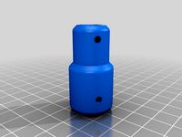
5mm to 8mm heavy duty coupler by wubwub89
...nt adapter/coupler for a 5mm shaft to 8mm leadscrew.
the design utilizes six m3 cap-heads and nuts to bind and locate the shafts.
thingiverse
free
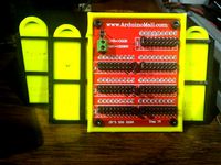
Decade resistor half-case by wubwub89
...e unit. the unit is from arduinomall.com, zero to 999,999 ohms. i have left enough room to remove jumpers, will add a photo soon.
thingiverse
free

Universal Phone holder for Desk (90deg, 15mm) by wubwub89
...ere is a provision for a charger in the bottom center. accepts phones up to 80mm+ by 15mm+, scale before slicing for other sizes.
thingiverse
free

Single switch mount universal, for US switches by wubwub89
...for line voltage ac! only acceptable for low voltage ac/dc projects that can use a standard 120 vac switch!
update: fixed bad stl
thingiverse
free

Simple cable anchor by wubwub89
...stener, ream appropriately. if you would like an additional change, post it in the comments, i will add more versions by request.
thingiverse
free

Wide M3 x 3mm spacers by wubwub89
...ed for use on a drone build, i will be printing these with tpu, other materials should work just as well.
id 3.2mm
od 10mm
h 3mm
thingiverse
free
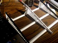
Generic laptop stand (12"+ printers only) by wubwub89
...rinting, you may wish to add some non-skid materials to the top and bottom. as this is universal, it is designed without notches.
thingiverse
free

Clip on photo-booth style photo frame by wubwub89
...uture, feel free to request in the comments section, i will get to it when i have free time. tips help for prioritizing requests!
thingiverse
free
Basic Desk Organizer (Fits 8.5x11" envelope) by wubwub89
... print the first unit!
thanks! please note, these are not for commercial use, personal use only with the cc license of this file!
Welder
thingiverse
free

welder
...welder
thingiverse
printed this to hold my filament welder
you will need supports
thingiverse
free

Filament welder by Tukanekb8
...filament welder by tukanekb8
thingiverse
this is my prototype of the filament welder.
thingiverse
free

Welder Holder by lugocain
...welder holder by lugocain
thingiverse
welder holder to amateur use
thingiverse
free

Chicago Electric Welder (Blue Welder) Hinge by esurplusplus
...der's case is up to you, i just glued in a short piece of threaded rod, and used the original nut to secure it to the welder.
thingiverse
free

Spot welder case by dunprojetalautre
...spot welder case by dunprojetalautre
thingiverse
lipo battery spot welder case.
thingiverse
free

welders respirator mask by elinamark
...welders respirator mask by elinamark
thingiverse
welders respirator mask
click to read
thingiverse
free

BIFRC Spot Welder housing
...bifrc spot welder housing
thingiverse
simple housing box for bifrc spot welder.
thingiverse
free

spot welder holder by kaa_snake
... welder holder.
my spot welder : https://www.amazon.fr/gp/product/b08dfy8y7j/ref=ppx_yo_dt_b_asin_title_o00_s00?ie=utf8&psc=1
thingiverse
free

Jawa Welder by nickorossa
...he pin with 100% infill for extra strength.
added a flame file to plug into the end of the nozzle. recommend printing trans-blue.
thingiverse
free

Welders Helmet by NinjaSwag
...welders helmet by ninjaswag
thingiverse
this is for people who like welding.
Novel
thingiverse
free

Novel object 2055
...quot; by dr. jessica horst and dr. michael hout.
you can print this as is or remix it to apply additional details you might want.
thingiverse
free

Novel object 2045
...d." by dr. jessica horst and dr. michael hout.
you can print this as is or remix to apply additional details you might want.
thingiverse
free

Novel object 2009
...t; by dr. jessica horst and dr. michael hout.
you can print this item and/or remix it to apply additional details you might want.
thingiverse
free

eggcentric egg cup for kids - novel egg cup
...eggcentric egg cup for kids - novel egg cup
thingiverse
eggcentric egg cup for kids - novel egg cup
thingiverse
free

Graphic Novel Wall Mounts by Dfrisby0
...oesn't damage the comic.
i attached each mount to the wall with small 3m velcro command strips for easy removal of the comic.
thingiverse
free

Novel Coronavirus by bathsheba
... -- good luck, and if it works out i'd love to see a picture.
ps if you'd like one in a glass cube i have those for sale.
thingiverse
free

Sampling Tube Stand for Hotgen Novel Antigen Test by urgsmurmel
...for hotgen novel antigen test by urgsmurmel
thingiverse
stand for the sampling tube from the covid19 antigen test kit by hotgen.
thingiverse
free

Dragonfly from Sci-Fi novel Rocheworld by EpicSpaceModels
... 49cm
hull diameter: 3cm
functions
canopy and led lighting
rotating vtol fans
rocheworld:https://en.wikipedia.org/wiki/rocheworld
thingiverse
free

KiLROY Helmet by camrylong
...the novel in the us here:https://www.amazon.com/kilroy-novel-benjamin-camry-long/dp/1539147568/ref=sr_1_1?ie=utf8&qid=1476996921&sr=8-1&keywords=kilroy+a+novel and in canada here:https://www.amazon.ca/kilroy-novelbenjamin-camry-long/dp/1539147568/ref=sr_1_1?ie=utf8&qid=1476996976&sr=8-1&keywords=kilroy+a+novel ...
thingiverse
free

Amulet medallion by tcombs
...is based off a design from the amulet graphic novel my son has been reading lately. the novels are...
Pulse
thingiverse
free

ADT Pulse Trim by Aikido_
...adt pulse trim by aikido_
thingiverse
trim to cover adt pulse wires
thingiverse
free

pulse logo heart by ulfy
...pulse logo heart by ulfy
thingiverse
just a quick pulse beat logo heart to share
thingiverse
free

The Mandalorian Pulse Rifle Cartridge
...the mandalorian pulse rifle cartridge
thingiverse
my version of the pulse rifle cartridge.
no disintegrations! wrong!
enjoy!
thingiverse
free

Vigilance Wing Pulse rifle by Ruben_NYC
...vigilance wing pulse rifle by ruben_nyc
thingiverse
destiny 2 exotic pulse
thingiverse
free

Cat Ears for Pulse 3D by RavensRule0309
...cat ears for pulse 3d by ravensrule0309
thingiverse
cat ears for the pulse 3d headset.
thingiverse
free

Colonial Marines Pulse Rifle by Rufian
...colonial marines pulse rifle by rufian
thingiverse
pulse rifle from aliens movie.
thingiverse
free

MACO pulse rifle by NX01Enterprise
...maco pulse rifle by nx01enterprise
thingiverse
i couldn't find a pulse rifle either, so i made one.
thingiverse
free

Withings Pulse Replacement Clip by Highcooley
...ement clip for the original withings pulse wristband. basically all you need is a withings pulse as well as a generic watch band.
thingiverse
free

The pulse cube by The_Random_Engineer
...d vacuum tube controlled by tesla coils and resonant transformers this is not the full thing but shows a much simplified version
thingiverse
free

M41A Pulse Rifle by Intentional3D
... intentional3d
thingiverse
this model is a 1:4 scale replica of the iconic pulse rifle from the movie aliens. xenomorphs beware!
Driven
thingiverse
free

Servo Driven Valve by mikedeklerk
...ven valve by mikedeklerk
thingiverse
a valve for liquids, driven by a servo motor. this way you could automate a flow of liquid.
thingiverse
free

DRIVEN pocket series track
...eries-blind-packs/-/a-52182975
dynamic quality, 20% infill. print 'thin' walls to show the dividers and h on the helipad.
thingiverse
free

Z driven pulley with rims by MBC
...ys.
the “2c†version of this part has a gear-toothed “c†(as in mbc) engraved in the top and bottom faces of the part.
â
thingiverse
free

10013 Z axis driven sprocket pulley by unexpectedly
...se
this is a direct replacement for the rapman 3.1 arylic driven sprocket on the driven axes. 3 of these are used in the rapman.
thingiverse
free

Watermill Driven Ballerina by jochoi0707
...watermill driven ballerina by jochoi0707
thingiverse
will upload a build-video soon, sorry about the delay!
thingiverse
free

Windmill - Driven Model for steam engines by AmmoMike83
...this is a rebuild of a wilesco m68 windmill. you can print and use it as a driven model for steam engines or just for decoration.
thingiverse
free

T-Case and S-Case for ATTiny85-Driven Intervalometer by td0g
...ttiny85-driven intervalometer. more info at https://gerritsendesign.wordpress.com/2017/12/13/attiny85-driven-intervalometer-diy/
thingiverse
free

Heliodors driven out of the Temple by GeoffreyMarchal
...nhagen, denmark). made with memento beta (now remake) from autodesk.
for more updates, please follow @geoffreymarchal on twitter.
thingiverse
free

Balloon driven car by yuvalabou
...r by yuvalabou
thingiverse
toy balloon car for students shop course.
just put the balloon on top and inflate from the exhaust :)
thingiverse
free

Pulley & Idler for string driven Rostock by Hendrik
...out every now and then as updates and/or additions may be uploaded.
http://yarrp.blogspot.com
facebook.com/yarrp
@yarrp3dprinting
Iteration
thingiverse
free

Iteration by AK_Eric
... reclaimed redwood. toopath generated in meshcam.
if you want to 3d print this, you'll need to make it a solid volume first.
thingiverse
free

Perfume Bottle Iterations by MakerBotPartnerLibrary
...the intricate final design, to be shown in a presentation. it is printed in translucent blue and translucent red, to mimic glass.
thingiverse
free

Iterated Functions System
...of reapplying a certain computation to a previous result. [iteration can be used in mathematics for getting closer approximations...
thingiverse
free

Nophead´s Mendel 90 iteration by SupaFly
...nopheadâ´s mendel 90 iteration by supafly
thingiverse
mendel 90 iteration for making it only with 10mm acrylic sheet
thingiverse
free
![[ 2017 PAULTINI ] : Ring : iterative by Paultini](/t/8701831.jpg)
[ 2017 PAULTINI ] : Ring : iterative by Paultini
...[ 2017 paultini ] : ring : iterative by paultini
thingiverse
https://instagram.com/paultini_official/
thingiverse
free

Skateboard Prototype One Second Iteration by ssernekos12
... working on.
this is the second iteration. i narrowed the front of the board so that it more accurately matched the back.
art 297
thingiverse
free

Iterated System Bamboo Shoots by TheHappyMew
...triangles were aligned to the corners of the previous iteration these systems form many common fractals ( https://en.wikipedia.org/wiki/fractal#common_techniques_for_generating_fractals )....
thingiverse
free

Prusa Iteration 2 Thick sheet (bed mount) by NikkeiRonin
...prusa iteration 2 thick sheet (bed mount) by nikkeironin
thingiverse
this is a heated bead mount of the prusa iteration 2.
thingiverse
free

iteration crossfire 2 feet by jorisk
...fire 2 feet by jorisk
thingiverse
shock absorbing feet for crossfire 2 quad
https://www.3dhubs.com/almere/hubs/kidman-nicholson
thingiverse
free

Cube Puzzle Iteration
...t is resizable.
blog post talking about puzzle in more detail: https://geekhaus.com/3dpuzzles/2020/01/13/jordan-brink-portfolio/
Spot
thingiverse
free

Spot by Ugunszellis
...spot by ugunszellis
thingiverse
experiment in works
thingiverse
free

Spotted Lanternfly
...spotted lanternfly
thingiverse
designed for printing and painting
thingiverse
free

LED Spot by MORP
...bling larger light installations.
we are using these spots as part of our mikrokopter project since three of them arew below 40g
thingiverse
free

Spot Light by vtozato
...spot light by vtozato
thingiverse
i made this spot to put it in my son's room.
thingiverse
free

Spotted Flower Pot
...spotted flower pot
thingiverse
this is a pretty but practical spotted flower pot. you plant a flower in it and watch it grow.
thingiverse
free

Spot Vase 2 by David_Mussaffi
...spot vase 2 by david_mussaffi
thingiverse
spot vase 2
thingiverse
free

Tripod for spotting scope by NorthDakota
...tripod for spotting scope by northdakota
thingiverse
tripod base for spotting scope
thingiverse
free

Hexagon GU10 Spot by kmltbtozgl
...hexagon gu10 spot by kmltbtozgl
thingiverse
hexagon gu10 spot light
thingiverse
free
Spot welder case by dunprojetalautre
...spot welder case by dunprojetalautre
thingiverse
lipo battery spot welder case.
thingiverse
free

Spot Vase 1 by David_Mussaffi
...spot vase 1 by david_mussaffi
thingiverse
spot vase 1https://youtu.be/bfybyorgirg
Dual
thingiverse
free

Dual 4010
...dual 4010
thingiverse
dual fan 4010
thingiverse
free

dual color cone for testing dual extruders by lovethepirk
...dual color cone for testing dual extruders by lovethepirk
thingiverse
dual color cone for testing dual extruders
thingiverse
free

Dual hook by duxdhell
...dual hook by duxdhell
thingiverse
dual hook
thingiverse
free

Headsetholder dual by J3M
...headsetholder dual by j3m
thingiverse
dual headset holder
thingiverse
free

Dual extruder by gustavorpinheiro
...dual extruder by gustavorpinheiro
thingiverse
this is a support for dual extruders.
thingiverse
free

Dual Plate by Jaimemarie
...dual plate by jaimemarie
thingiverse
toggle and dual outlet plate
thingiverse
free

Dual IEC by mrkrash
...dual iec by mrkrash
thingiverse
dual hotend with fine regulation
thingiverse
free

Dual Spinner by AidanSandersSAN
...dual spinner by aidansanderssan
thingiverse
a dual spinner i made in class.
thingiverse
free

Dual Spinner by groman
...dual spinner by groman
thingiverse
a quick remix of the tri spinner. a dual spinner!
thingiverse
free

Dual stepper mount
...dual stepper mount
thingiverse
dual stepper mount. drill mounting holes for printer
A
thingiverse
free

IKEA Vaxer net pot by khrazik
...ymore in my neighborhood, so i made my own. fits standard vaxer tubs. these are meant to be printed upside down with no supports.
thingiverse
free

Quiet control box for SKR 1.4 + cable mgmt layer. by Evilkoal
...thing into the electronics of the power supply.
let me know if anything is weird, but i haven't noticed anything not fitting.
thingiverse
free

UVA Mens' Basketball 2018-19 NCAA Trophy by the_qsr
...tube.com/watch?v=hxa3xd4dxcy
i've added a blank uva trophy in .stl and .obj for any other sports/years that you want to remix
thingiverse
free

Volcano Nozzle Case by garethps
...er nozzles. i could have just stretched it but then the number inserts wouldn't have fit properly, hence my first ever remix!
thingiverse
free

Savage Dragon - Image Comics by ZMilab
...s in my mini style.
if you want more models released weekly and access to exclusives join my patreon!
patreon.com/ziemba3d
enjoy!
thingiverse
free

Concordia and Britannia & Germania expansion boardgame insert by MitutoyoRaytek
...pacer2-v2.stl. i butchered my cardboard insert and turned it into a spacer.
spacer1-v2.stl is designed for printing in vase mode.
thingiverse
free

Renna by Legname
...renna by legname
thingiverse
renna in compensato da 3mm
thingiverse
free

Extension Cord Cable Mount Clip by max_davis
...x_davis
thingiverse
cable mount that fits a standard extension cord cable (up to 9mm). just use two screws or nails to mount it.
thingiverse
free

VESA monitor mount French Cleat by Rockster160
...ing/using this you claim all responsibility due to damage. use at your own risk!
fastened them to the monitors using m4*12 bolts.
thingiverse
free

GBS Zero Rain / Reverse Light IVA Angled Gasket by SeanWally
...pu.
the design includes a small seat adapter make sure that bolts used to secure the light are still mating at the correct angle.