Thingiverse
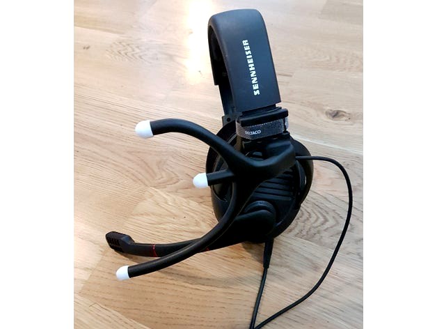
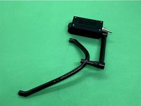
TrackIR LED holder by BoopidooDesigns
by Thingiverse
Last crawled date: 3 years ago
NOTICE: It is not allowed to print and sell this design on eBay (or anywhere else). It does not matter if you change the design. Please read licence information.
I needed a better LED holder so I made my own. To clarify this design works for TrackIR as well as OpenTrack etc software.
As always, if you find it useful a tiny donation goes a long way to show appreciation. :)
Parts needed:
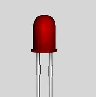
3pcs IR LEDs
1pcs resitor (or if you can't match the exact value combine two in parallel)
1pcs PTC fuse of at least 3xIf (for me 300mA).
4pcs thin wires (I used 26 AWG) I call these cables 1-4 in the description.
1pcs thin steel wire ~20cm
1pcs DC-power source with cable (or USB cable)
1pcs velcro strip
Using the LED Series array wizard (http://led.linear1.org/led.wiz) I find that for three LEDs (Vf=1.2-1.4 If=100mA) in series powered by 5 VDC results in me needing a resistor @8.2ohms
Using a parallel resistor calculator (http://www.sengpielaudio.com/calculator-paralresist.htm) and using the combination of resitsors I have at hand I get almost exactly 8.2ohms by using two resistors, 10 & 47ohms, in parallel.
I use a PTC fuse @ 300mA just in case to protect my power source (either a separate PSU or the motherboard if I use USB for power).
I've used the scematics in this link and built my setup according to it but with other components: http://myfreetrackheadset.blogspot.se/
Step 1. Pull the steel wire through the bottom LED opening all the way through the frame until it comes out on the back.
Step 2. Bend wire and attach cable 3&4, pull cable through the frame. Let the cable out at least 5cm so it won't get pulled into the frame when meesing with the other cables.
Step 3. Repeat step 1-2 but thrugh the top LED opening and cable 1&2.
Step 4. Push steel wire through the middle LED opening.
Step 5. Attach the ends of cable 2 & 3 and pull through the frame.
Step 6. Solder LEDs take note of the polarity and solder them in series. I used shrink tube to protect the pins from shorting.
Step 7. Push in the LEDs into the frame and pull carefully on cable 1 & 4 to get rid on uneccessary excess cable inside the frame.
Step 8. Solder resistor and fuse on positive cable.
Step 9. Insert power source cable into the cable through the pull release holes in the frame.
Step 10. Solder power cable onto cable 1 & 4, take note of the polarity.
Step 11. Push excess cable, resistor and fuse into the frame.
Step 12. Try out the LEDs with your mobile phone camera, if you bought narrow angle LEDs like me you might need to use the omni bouncers.
EDIT: I added a small part for a switch. A little tricky to fit everything but it it's do-able. Also added pictures on how I do it.
Enjoy!
I needed a better LED holder so I made my own. To clarify this design works for TrackIR as well as OpenTrack etc software.
As always, if you find it useful a tiny donation goes a long way to show appreciation. :)
Parts needed:
3pcs IR LEDs
1pcs resitor (or if you can't match the exact value combine two in parallel)
1pcs PTC fuse of at least 3xIf (for me 300mA).
4pcs thin wires (I used 26 AWG) I call these cables 1-4 in the description.
1pcs thin steel wire ~20cm
1pcs DC-power source with cable (or USB cable)
1pcs velcro strip
Using the LED Series array wizard (http://led.linear1.org/led.wiz) I find that for three LEDs (Vf=1.2-1.4 If=100mA) in series powered by 5 VDC results in me needing a resistor @8.2ohms
Using a parallel resistor calculator (http://www.sengpielaudio.com/calculator-paralresist.htm) and using the combination of resitsors I have at hand I get almost exactly 8.2ohms by using two resistors, 10 & 47ohms, in parallel.
I use a PTC fuse @ 300mA just in case to protect my power source (either a separate PSU or the motherboard if I use USB for power).
I've used the scematics in this link and built my setup according to it but with other components: http://myfreetrackheadset.blogspot.se/
Step 1. Pull the steel wire through the bottom LED opening all the way through the frame until it comes out on the back.
Step 2. Bend wire and attach cable 3&4, pull cable through the frame. Let the cable out at least 5cm so it won't get pulled into the frame when meesing with the other cables.
Step 3. Repeat step 1-2 but thrugh the top LED opening and cable 1&2.
Step 4. Push steel wire through the middle LED opening.
Step 5. Attach the ends of cable 2 & 3 and pull through the frame.
Step 6. Solder LEDs take note of the polarity and solder them in series. I used shrink tube to protect the pins from shorting.
Step 7. Push in the LEDs into the frame and pull carefully on cable 1 & 4 to get rid on uneccessary excess cable inside the frame.
Step 8. Solder resistor and fuse on positive cable.
Step 9. Insert power source cable into the cable through the pull release holes in the frame.
Step 10. Solder power cable onto cable 1 & 4, take note of the polarity.
Step 11. Push excess cable, resistor and fuse into the frame.
Step 12. Try out the LEDs with your mobile phone camera, if you bought narrow angle LEDs like me you might need to use the omni bouncers.
EDIT: I added a small part for a switch. A little tricky to fit everything but it it's do-able. Also added pictures on how I do it.
Enjoy!
Similar models
grabcad
free

My TrackIR Design
...
vous aurez besoin de :
• 3 x led ir sfh485p
• 1 x résistance 10 ohm
• 1 x fusible ptc 250 ma
• 1 x cable usb
• 4 x cables (+5 v)
thingiverse
free

HYPERLITE FLOSS 3.0 (LED mount, Immortal-T antenna mount) by FpvBeyondEarth
...de of the led board and solder the cable directly to the esc.
i used these led's:https://www.banggood.com/custlink/gdvyw4yr5p
thingiverse
free
TrackIR TrackClip PRO Battery Compartment Headphones Clip by falken_gt4
...der the red wire to the leds to the other terminal on the switch.
4) make sure to insulate properly, i used heat shrink sleeving.
thingiverse
free

3D printer light by WillemvD
...gh the opening to make room for the four resistors. use a piece of doubble sided adhesive foam to attach it wherever you want it.
thingiverse
free

3MM LED Frame Clamp for Wanhao Duplicator i3/Monoprice Maker select by DaBeast725
...ight on the inside of the printer. the mount design is the fifth (5th) revision. i wanted to make it perfect before uploading it.
thingiverse
free

trackir pro no clip 18650 battery by speed100011
...e+protection dual functions tp4056 18650
to help you find the resitor value with the ir ledshttp://led.linear1.org/led.wiz
enjoy!
thingiverse
free

Fibonacci Spiral Night Light by elwood127
...s upside down. it is correct now. thanks.
i would change the 68 ohm resistor for a 470 ohm. led's started to dim over time .
thingiverse
free

RGB Lighting for Kolink Rocket Push Power Button with Asus Aura
...is used for the power switch cable,
the three drillings off-center for the leds.
if you have further questions, feel free to ask.
thingiverse
free

USB desk lamp by K_Sherman
...once i've tested the bulb i pot the assembly in hot melt glue.
for hardware i use 2x 1/4-20 x 1in bolts and 2x 1/4-20 nuts.
thingiverse
free

tube fuse holder mounting by Cube2014
...tube fuse holder mounting by cube2014
thingiverse
this is a fuse holder for a 4mm wire.
use for serie / parallel education
Trackir
thingiverse
free

TrackIR by Korop
...port touching buildplate only for the trackir.
you'll find the arduino support here:https://www.thingiverse.com/thing:4771938
thingiverse
free

TrackIR reflector attachment by Mape
...ttachment by mape
thingiverse
pieces to allow permanent mounting of trackir reflector to a baseball cap with a couple of screws.
thingiverse
free

Logitech G930 TrackIR TrackClip clip by whttigress
... for the official trackir trackclip to slide into. you will need support material for the channel the trackir trackclip sits in.
thingiverse
free

TrackClip hat for Trackir by astfede
...ated 3 point trackclip for trackir or infrared webcam,
print at 0.2 infill 20% and apply 3 small pieces of reflective tape.
enjoy
thingiverse
free

TrackIR Band by alan1for
...ent exactly as it is out of the box.
also included is a hook to hang it on, use double sticky tape to stick it anywhere you like.
thingiverse
free

TrackIR Pro clip by l3vgv
...trackir pro clip by l3vgv
thingiverse
trackir5 pro clip, with correct sized and displacements.
thingiverse
free

TrackIR 4 Clamp by koelooptiemanna
...trackir 4 clamp by koelooptiemanna
thingiverse
alternative clamp. originally made for imac screens
thingiverse
free

TrackIR 5 holder clip by RabbitEngineering
...flat screen monitors. use this to build your own stand!
has three lightening holes, controlled parametrically in the scad file.
thingiverse
free

Clip TrackIR Astro A40 by tmandel
... so it can fit with that model https://www.thingiverse.com/thing:707734 also works with https://www.thingiverse.com/thing:4823994
thingiverse
free

Bracket for broken TrackIR TrackClip Pro by etotman
...ir trackclip pro by etotman
thingiverse
the small plastic pieces inside my trackclip pro broke so i made this bracket to fix it.
Boopidoodesigns
thingiverse
free

Samsung S4 Holder by BoopidooDesigns
...samsung s4 holder by boopidoodesigns
thingiverse
same as my other holder but with no usb-charge holder.
thingiverse
free

QAV250 Skid Plate by BoopidooDesigns
...qav250 skid plate by boopidoodesigns
thingiverse
this skid plate doubles as landing gear as well as protection for the pdb.
thingiverse
free

Cable Strain Relief by BoopidooDesigns
...e strain relief by boopidoodesigns
thingiverse
a quick and simple design that reliefs the connector from the weight of the lamp.
thingiverse
free

Pen holder with a twist by BoopidooDesigns
...holder with a twist by boopidoodesigns
thingiverse
generic holder for pens and other stuff that's laying around on the desk.
thingiverse
free

Coffee Filter Holder by BoopidooDesigns
...r holder by boopidoodesigns
thingiverse
needed this at home and didn't like the clumsy alternative in wood we currently had.
thingiverse
free

Filament spool holder by BoopidooDesigns
...ns
thingiverse
a filament spool holder made to fit the kajakmannen plexiglass enclosure: http://www.thingiverse.com/thing:125599
thingiverse
free

Filament Spool Holder (no axle) by BoopidooDesigns
...filament spool holder (no axle) by boopidoodesigns
thingiverse
on this spool holder the roll sits on bearings to roll easier.
thingiverse
free

DJI Naza-M V1 by BoopidooDesigns
...dji naza-m v1 by boopidoodesigns
thingiverse
dji naza-m v1 to be used when designing accessories.
thingiverse
free

Solder Tip Holder by BoopidooDesigns
...ingiverse
solder tip holder for solder tips with an outside diameter of <7.5mm. this fits my hakko 900-series tips perfectly.
thingiverse
free

QAV250 Landing gears by BoopidooDesigns
...se by lumenier. the gears are easy to assemble using m3 knurl nuts and a soldering iron but standard m3-nuts can be used as well.
Led
3d_export
$5
led
...led
3dexport
the led is cut with all the parts.
3ddd
$1
Monacor / PARL56DMX / LED-320RGBW / LED-345RGBW / LED-300RGB
... прожектор
http://www.monacor.dk/
parl56dmx
led-320rgbw
led-345rgbw
led-300rgb
turbosquid
$10
LED
...led
turbosquid
free 3d model led for download as blend on turbosquid: 3d models for games, architecture, videos. (1691856)
3d_export
$5

led lamp
...led lamp
3dexport
led lamp, brightness animation
3ddd
free
leds-c4
...leds-c4
3ddd
leds-c4
современный торшер
3ddd
free
leds-c4
...leds-c4
3ddd
leds-c4
настольный лампа
turbosquid
$19
LED
... available on turbo squid, the world's leading provider of digital 3d models for visualization, films, television, and games.
turbosquid
$12
Led
... available on turbo squid, the world's leading provider of digital 3d models for visualization, films, television, and games.
turbosquid
free
LED
... available on turbo squid, the world's leading provider of digital 3d models for visualization, films, television, and games.
turbosquid
free
LED
... available on turbo squid, the world's leading provider of digital 3d models for visualization, films, television, and games.
Holder
archibase_planet
free

Holder
...holder
archibase planet
holder toilet paper holder
holder paper n070712 - 3d model (*.gsm+*.3ds) for interior 3d visualization.
archibase_planet
free
Holder
...e planet
holder rack toilet paper holder
holder toilet roll n240715 - 3d model (*.gsm+*.3ds+*.max) for interior 3d visualization.
archibase_planet
free
Holder
...holder
archibase planet
pen holder support prop
pen holder - 3d model for interior 3d visualization.
archibase_planet
free
Holder
...holder
archibase planet
pole post holder
сhurch cross pole holder - 3d model for interior 3d visualization.
archibase_planet
free
Holder
...holder
archibase planet
holder bathroom ware
shower holder - 3d model (*.gsm+*.3ds) for interior 3d visualization.
archibase_planet
free

Holder
...oilet paper holder
holder paper devon&devon; time black n241113 - 3d model (*.gsm+*.3ds+*.max) for interior 3d visualization.
archibase_planet
free
Holder
...holder
archibase planet
holder hanger hanger for towel
holder 7 - 3d model (*.gsm+*.3ds) for interior 3d visualization.
archibase_planet
free
Holder
...holder
archibase planet
holder hanger hanger for towel
holder 3 - 3d model (*.gsm+*.3ds) for interior 3d visualization.
archibase_planet
free
Holder
...holder
archibase planet
holder towel rack towel-horse
holder - 3d model (*.gsm+*.3ds) for interior 3d visualization.
archibase_planet
free
Holder
...lder
archibase planet
holder hanger hanger for towel
holder towel n250912 - 3d model (*.gsm+*.3ds) for interior 3d visualization.