Thingiverse
Tinkering the Ivan Miranda Big Printer to a smaller version (Completed) by 3D_PP
by Thingiverse
Last crawled date: 3 years ago
The original design of this printer lays in the hands of Ivan Miranda.
More info about this printer design can be found here https://ivanmiranda.com/?p=1645
No doubt to say, we love this design due it's simplicity in configuration and build. Thumbs up for Ivan.
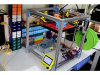
As this is a very BIG printer, 300 x 600 x 300 mm, we at 3D Prototype Printing decided to adjust a bit of the dimensions, 300 x 300 x 500 mm, as that suits us more.
Using the B.O.M. posted by Ivan, we simply redone the numbers of the posted lengths towards the rods, the 20 x 20 x 1.5 mm square aluminum extrusions and the M8 Lead screw to get what we needed.
Either we made a mistake in the mats, or the print area is not 300 x 600 mm posted.
We came out (after the build) on 195 x 295 mm with a height of 450 mm,
20 mm should be added in the y direction, 105 mm + the size of the carriage should be added to the x direction (about 185 mm). and 50 mm into the z direction
Note: If you going to make use of the new type "Bed holder" then the Z direction only needs to be corrected with 20 mm.
As we wanted to have this printer in prototype state, we opted for cheaper materials.
For example, the smooth rods have been replaced with chromed stainless steel pipes of 12mm, the x bridging has been replaced with an aluminum 8mm rod. The bed is made out of wood, yes, no metal as we don't use a heated bed. Still, we most likely stay with the wooden bed, or a printed version for it with use of extra insulation materials.
After cutting all materials to length and printing all the posted parts from his Fusion 360 link https://myhub.autodesk360.com/ue29ae852/g/shares/SH7f1edQT22b515c761eda136a61687c5365 we started to build the printer.
On his website he wrote about using this Fusion 360 to update all his parts. We came to the conclusion that this was not fully true. During his build he made adjustments to the printer that did not show up in this build. But that didn't matter as some of his adjustments are on his webpage (link above).
We noticed, after printing the Y-Carriage, the holes for the LM12UU were like 1 mm to large, strange as he used his screwdriver to hammer them in, ours just made use of the gravity, Tinkering was needed to get this printer going like we wanted it to go, after all we had almost all the parts available.
One thing that we were missing was a holder for the filament stepper, already posted here https://www.thingiverse.com/thing:2630201.
Ivan his design of the bed is of a massive weight, 2 times 6 mm aluminum plate, 3 cork layers, a 300 x 600 mm mirror, 2 heat beds of 300 x 300 mm and 2 solid state relays mounted to the bottom of the print bed. (HEAVY)
We wanted to go light so that is why we used the wood. Problem we got with that is, it is shaking all over the place do not enough weight, though we stick on the wood for now and see if we can come to a solution. (already redesigned a few parts for it)
First of all this:
Parts that you can print straight of the original build.
This list shows the parts we used without any adjustments, off course you can print all the originals from Ivan his design as we did also to start with.
Overall list of original parts, used by 3DPP:
T2020 20x needed
E2020 20x needed
Bracket front (2 parts for power supply)
Bracket back (2 parts for power supply)
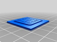
LCD Screen (4 parts including the reset knob)
Arduino Ramps Controler (2 parts)
End Stop Support (Limit Switch) (2 parts) (Probably will be updated for Dual Z- Limit Switch Support)
X-Axis parts (Although those parts are called Y-, from my point of view, the position / placing of the LCD makes those X- related)
Y-Guide Bracket Motor (2 parts, part for X-axis motion of the Y-axis, holds the dual axis NEMA 17, locking the X-axis)
Y-Guide Bracket (1 part, holds the 608 bearing to guide the rod coming from Y-Guide Bracket Motor, locking the X-axis (use Y-Guide Bracket Upper))
Y-Guide Bracket Upper (1 part (3x needed) to clamp the 12 mm X-Axis rods in place)
Bracket Tensioner (1 part, Part to lock the 12 mm X-Axis (use Y-Guide Bracket Upper) and the GT2 Belt Tensioner)
Bracket Tensioner mirror (1 part, Part to lock the 12 mm X-Axis (use Y-Guide Bracket Upper) and the GT2 Belt Tensioner)
Belt Tensioner (3x needed)
Y-Axis parts
Bridge Motor Side (1 part, the top part of the bridge that holds the NEMA in place)
All other parts of the Y-Axis are modified.
Still you can print all the originals, all up to you.
Z-Axis parts
The Z-Axis consist out of 4 parts, the motor holder (2x needed), the clamp for the motor holder (2x needed), the bed holder (2x needed) and the clamp for the guide rail on the bottom (4x needed).
Point of attention:
If you donwload the files from Fusion 360, the motor holder and the clamp for the motor holder missing the hole to lock the guide rail in place.
Only part we used:
Clamp Guide Rail Bottom (4x needed)
All other parts of the Z-Axis are modified.
Still you can print all the originals, all up to you.
We will frequently update this page (until done) with all the updates.
So for all that are making this printer or planning to make this printer, those updates might be useful to you.
Note: All settings posted are the settings we used, feel free if you want to change them to make it more stirdy.
The updates:
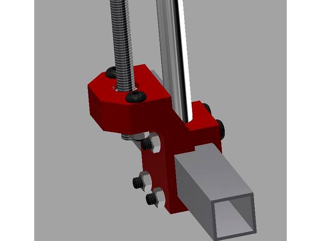
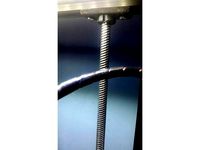
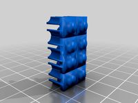
Reducing the M8 Lead screw wobbling: added a holder to the bottom with an extra 608 bearing (3 Parts to print, 0.2 layer, 40% infill, no rafts, no supports)
z-axis 12mm centering guide bottom bearing (print laying on the side)
z-axis 12mm centering guide bottom
z-axis 608zz locker (any 608 will do)
Avoiding running out of the M8 nut from the Bed Plate Holder on long Z-Axis travel (minor update if you use the original Bed Plate Holder)
Nut Lock Plate (2x needed) 0.2 layer, 100% infill, no rafts, no supports)
Guide rod holder for Z-Axis to replace the Limit Switch Holder (preparing for dual Z limit Switch)
axis holder 12mm 35 mm inside frame (1x needed) 0.2 layer, 20% infill, no rafts, no supports)
Axis holder 12mm 35mm outside frame with cable tray (1x needed) 0.2 layer, 20% infill, no rafts, no supports)
Limit Switch holder to fit on 35 mm axis holder (2x needed if you go for dual Z Limit Switch) 0.2 layer, 100% infill, no rafts, no supports)
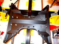
Replacement for the Bed Holders, those will replace the ones that are shown in post 2. Switching from 1 guided rod to 2 guided rods on the Z-Axis.
Bed holder (2x needed 0.2 layer, 30% infill, no rafts, no supports)
M8 Nut holder (2x needed 0.2 layer, 100% infill, no rafts, no supports)
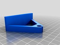
Spool Holder, we need a spool holder. Despite there are a zillion on TV, i could not find one made for the 20 x 20 mm square tube, also needs to be able to hold a 300 mm spool.
20 x 20 clamp for spool holder (2x needed) 0.2 layer, 20% infill, no rafts, no supports)
Spool Holder (1x needed) 0.2 layer, 30% infill, no rafts, no supports)
X-Motor carriage: Changed to have a better alignment when locking the rods in place and a clamp mechanism to have the belt more secure and easier mounting. The LM12UU has a very snug fit.
X-carriage Bridge Motor side (1x needed) 0.2 layer, 30% infill, no rafts, no supports)
Cable holder V2 right hand side (1x needed per X-carriage 0.2 layer, 100% infill, no rafts, no supports)
Cable holder V2 left hand side (1x needed per X-carriage 0.2 layer, 100% infill, no rafts, no supports)
X-carriage Bridge Pulley side. Changed to have a better alignment when locking the rods in place and a clamp mechanism to have the belt more secure and easier mounting. The LM12UU has a very snug fit.
X-carriage Bridge Pulley side (1x needed) 0.2 layer, 30% infill, no rafts, no supports)
Cable holder V2 right hand side (1x needed per X-carriage 0.2 layer, 100% infill, no rafts, no supports)
Cable holder V2 left hand side (1x needed per X-carriage 0.2 layer, 100% infill, no rafts, no supports)
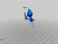
Y-Carriage. Changed to carry 30 mm fan mounting spots (extruder + part cooling). The LM12UU has a very snug fit. Designed to fit a Heatsink of 31 / 32 mm in max height (Total height of all the cooling ribs). The part cooling fan positioned at the bottom need to be slide in from the side, only 2 screws needed to keep it in place.
Y-Carriage (1x needed) 0.2 layer, 40% infill, no rafts, supports needed, see photo's)
Y-Carriage Belt clamp (2x needed 0.2 layer, 100% infill, no rafts, no supports)
E3D Clamp (1x needed 0.2 layer, 100% infill, no rafts, no supports)
NOTE
For the Y-Carriage, print it at 30 mm/s.
The last photo shows the carriage after a 5 and a half hour print on 205 C. Yes, it is just PLA.
Raw, non calibrated printer Benchy test as result after all the updates. Printed at 0.2 layer @ 60 mm/s.
Done
In case we come up with more updates, we will off-course post them.
3DPP wish all the people that are building or planning on building this printer "Happy Printing"
More info about this printer design can be found here https://ivanmiranda.com/?p=1645
No doubt to say, we love this design due it's simplicity in configuration and build. Thumbs up for Ivan.
As this is a very BIG printer, 300 x 600 x 300 mm, we at 3D Prototype Printing decided to adjust a bit of the dimensions, 300 x 300 x 500 mm, as that suits us more.
Using the B.O.M. posted by Ivan, we simply redone the numbers of the posted lengths towards the rods, the 20 x 20 x 1.5 mm square aluminum extrusions and the M8 Lead screw to get what we needed.
Either we made a mistake in the mats, or the print area is not 300 x 600 mm posted.
We came out (after the build) on 195 x 295 mm with a height of 450 mm,
20 mm should be added in the y direction, 105 mm + the size of the carriage should be added to the x direction (about 185 mm). and 50 mm into the z direction
Note: If you going to make use of the new type "Bed holder" then the Z direction only needs to be corrected with 20 mm.
As we wanted to have this printer in prototype state, we opted for cheaper materials.
For example, the smooth rods have been replaced with chromed stainless steel pipes of 12mm, the x bridging has been replaced with an aluminum 8mm rod. The bed is made out of wood, yes, no metal as we don't use a heated bed. Still, we most likely stay with the wooden bed, or a printed version for it with use of extra insulation materials.
After cutting all materials to length and printing all the posted parts from his Fusion 360 link https://myhub.autodesk360.com/ue29ae852/g/shares/SH7f1edQT22b515c761eda136a61687c5365 we started to build the printer.
On his website he wrote about using this Fusion 360 to update all his parts. We came to the conclusion that this was not fully true. During his build he made adjustments to the printer that did not show up in this build. But that didn't matter as some of his adjustments are on his webpage (link above).
We noticed, after printing the Y-Carriage, the holes for the LM12UU were like 1 mm to large, strange as he used his screwdriver to hammer them in, ours just made use of the gravity, Tinkering was needed to get this printer going like we wanted it to go, after all we had almost all the parts available.
One thing that we were missing was a holder for the filament stepper, already posted here https://www.thingiverse.com/thing:2630201.
Ivan his design of the bed is of a massive weight, 2 times 6 mm aluminum plate, 3 cork layers, a 300 x 600 mm mirror, 2 heat beds of 300 x 300 mm and 2 solid state relays mounted to the bottom of the print bed. (HEAVY)
We wanted to go light so that is why we used the wood. Problem we got with that is, it is shaking all over the place do not enough weight, though we stick on the wood for now and see if we can come to a solution. (already redesigned a few parts for it)
First of all this:
Parts that you can print straight of the original build.
This list shows the parts we used without any adjustments, off course you can print all the originals from Ivan his design as we did also to start with.
Overall list of original parts, used by 3DPP:
T2020 20x needed
E2020 20x needed
Bracket front (2 parts for power supply)
Bracket back (2 parts for power supply)
LCD Screen (4 parts including the reset knob)
Arduino Ramps Controler (2 parts)
End Stop Support (Limit Switch) (2 parts) (Probably will be updated for Dual Z- Limit Switch Support)
X-Axis parts (Although those parts are called Y-, from my point of view, the position / placing of the LCD makes those X- related)
Y-Guide Bracket Motor (2 parts, part for X-axis motion of the Y-axis, holds the dual axis NEMA 17, locking the X-axis)
Y-Guide Bracket (1 part, holds the 608 bearing to guide the rod coming from Y-Guide Bracket Motor, locking the X-axis (use Y-Guide Bracket Upper))
Y-Guide Bracket Upper (1 part (3x needed) to clamp the 12 mm X-Axis rods in place)
Bracket Tensioner (1 part, Part to lock the 12 mm X-Axis (use Y-Guide Bracket Upper) and the GT2 Belt Tensioner)
Bracket Tensioner mirror (1 part, Part to lock the 12 mm X-Axis (use Y-Guide Bracket Upper) and the GT2 Belt Tensioner)
Belt Tensioner (3x needed)
Y-Axis parts
Bridge Motor Side (1 part, the top part of the bridge that holds the NEMA in place)
All other parts of the Y-Axis are modified.
Still you can print all the originals, all up to you.
Z-Axis parts
The Z-Axis consist out of 4 parts, the motor holder (2x needed), the clamp for the motor holder (2x needed), the bed holder (2x needed) and the clamp for the guide rail on the bottom (4x needed).
Point of attention:
If you donwload the files from Fusion 360, the motor holder and the clamp for the motor holder missing the hole to lock the guide rail in place.
Only part we used:
Clamp Guide Rail Bottom (4x needed)
All other parts of the Z-Axis are modified.
Still you can print all the originals, all up to you.
We will frequently update this page (until done) with all the updates.
So for all that are making this printer or planning to make this printer, those updates might be useful to you.
Note: All settings posted are the settings we used, feel free if you want to change them to make it more stirdy.
The updates:
Reducing the M8 Lead screw wobbling: added a holder to the bottom with an extra 608 bearing (3 Parts to print, 0.2 layer, 40% infill, no rafts, no supports)
z-axis 12mm centering guide bottom bearing (print laying on the side)
z-axis 12mm centering guide bottom
z-axis 608zz locker (any 608 will do)
Avoiding running out of the M8 nut from the Bed Plate Holder on long Z-Axis travel (minor update if you use the original Bed Plate Holder)
Nut Lock Plate (2x needed) 0.2 layer, 100% infill, no rafts, no supports)
Guide rod holder for Z-Axis to replace the Limit Switch Holder (preparing for dual Z limit Switch)
axis holder 12mm 35 mm inside frame (1x needed) 0.2 layer, 20% infill, no rafts, no supports)
Axis holder 12mm 35mm outside frame with cable tray (1x needed) 0.2 layer, 20% infill, no rafts, no supports)
Limit Switch holder to fit on 35 mm axis holder (2x needed if you go for dual Z Limit Switch) 0.2 layer, 100% infill, no rafts, no supports)
Replacement for the Bed Holders, those will replace the ones that are shown in post 2. Switching from 1 guided rod to 2 guided rods on the Z-Axis.
Bed holder (2x needed 0.2 layer, 30% infill, no rafts, no supports)
M8 Nut holder (2x needed 0.2 layer, 100% infill, no rafts, no supports)
Spool Holder, we need a spool holder. Despite there are a zillion on TV, i could not find one made for the 20 x 20 mm square tube, also needs to be able to hold a 300 mm spool.
20 x 20 clamp for spool holder (2x needed) 0.2 layer, 20% infill, no rafts, no supports)
Spool Holder (1x needed) 0.2 layer, 30% infill, no rafts, no supports)
X-Motor carriage: Changed to have a better alignment when locking the rods in place and a clamp mechanism to have the belt more secure and easier mounting. The LM12UU has a very snug fit.
X-carriage Bridge Motor side (1x needed) 0.2 layer, 30% infill, no rafts, no supports)
Cable holder V2 right hand side (1x needed per X-carriage 0.2 layer, 100% infill, no rafts, no supports)
Cable holder V2 left hand side (1x needed per X-carriage 0.2 layer, 100% infill, no rafts, no supports)
X-carriage Bridge Pulley side. Changed to have a better alignment when locking the rods in place and a clamp mechanism to have the belt more secure and easier mounting. The LM12UU has a very snug fit.
X-carriage Bridge Pulley side (1x needed) 0.2 layer, 30% infill, no rafts, no supports)
Cable holder V2 right hand side (1x needed per X-carriage 0.2 layer, 100% infill, no rafts, no supports)
Cable holder V2 left hand side (1x needed per X-carriage 0.2 layer, 100% infill, no rafts, no supports)
Y-Carriage. Changed to carry 30 mm fan mounting spots (extruder + part cooling). The LM12UU has a very snug fit. Designed to fit a Heatsink of 31 / 32 mm in max height (Total height of all the cooling ribs). The part cooling fan positioned at the bottom need to be slide in from the side, only 2 screws needed to keep it in place.
Y-Carriage (1x needed) 0.2 layer, 40% infill, no rafts, supports needed, see photo's)
Y-Carriage Belt clamp (2x needed 0.2 layer, 100% infill, no rafts, no supports)
E3D Clamp (1x needed 0.2 layer, 100% infill, no rafts, no supports)
NOTE
For the Y-Carriage, print it at 30 mm/s.
The last photo shows the carriage after a 5 and a half hour print on 205 C. Yes, it is just PLA.
Raw, non calibrated printer Benchy test as result after all the updates. Printed at 0.2 layer @ 60 mm/s.
Done
In case we come up with more updates, we will off-course post them.
3DPP wish all the people that are building or planning on building this printer "Happy Printing"
Similar models
thingiverse
free
Parametric Prusa i3 Frame Stabilizer kit by projunk
...(2x) (back)
m10 threaded rod 394 mm (2x) (y-axis)
m10 threaded rod 385 mm (2x) (sloping)
m10 nuts (46x)
m10 washers (46x)
thingiverse
free
OX-Metal CNC Router Mill by Schematix
...m router mount, and 2x router band clamp cover
features video about the ox-metal here https://www.youtube.com/watch?v=uogjfrgvj7o
thingiverse
free
Anet A6 Calibration tools by fierland
...
16.05.2018 made small change to z-axis clamp made room for belt. and added x-axis clamp for original a6 x-carriage (not tested).
thingiverse
free

FLSun i3 Factory Printable Parts Collection (linear rod and bearing version) by macelius
...xis belt tensioner (2 parts)
y-axis bed rail mounts
z-axis top corner brackets - 10mm tall
z-axis top corner brackets - 40mm tall
thingiverse
free
Remix of Ulticube by shivackt
... m2 8mm (for the hotend)
2x m3 22mm (for the part cooler)
https://youtu.be/60zclhke-rehttps://www.youtube.com/watch?v=izpw6stqzsy
thingiverse
free

Ekobots - Box-H 3D Printer. by jsirgado
...gs like this.
buy my designs at pinshape:http://pinshape.com/users/27920-jsirgado
the openscad file is there, you can change all.
thingiverse
free
Z axis guide by rikkie2000
...z axis guide by rikkie2000
thingiverse
layer 0.2 infill 20%
thingiverse
free
Robo3D Printer Z Axis Rod Support by Director
...or
thingiverse
remix of billyant's nice design. i added a bracket to the right support to hold the x carriage wire harness.
thingiverse
free

Suicide SQUAD by sMiky
...suicide squad by smiky
thingiverse
makerbot replicator 2x
raft - on
infill - 20%
layer height - 0.2 mm
thingiverse
free
Tevo Tarantula 8mm Rod Y-Axis and Printed Bed Support by evil_k
....thingiverse.com/thing:1580899
other brackets on bottom of tevo tarantula by thingirob: https://www.thingiverse.com/thing:1457449
Miranda
3ddd
$1
Miranda B
...miranda b
3ddd
miranda , журнальный
длина - 117см
высота - 48см
ширина - 40см
3ddd
$1
VENETA SEDIE / Miranda
... sedie / miranda
3ddd
veneta sedie , пуф
пуф
производитель: veneta sedie
модель: miranda
3d_export
$9

Miranda 3D Model
...miranda 3d model
3dexport
girl best sexy sex good
miranda 3d model sergey268 39635 3dexport
3ddd
$1
Софа Miranda
...а миранда компании sevensedie
сайт фирмы:http://www.sevensedie.com/
...
высота: 112 cm
ширина: 119 cm
глубина: 76 cm
turbosquid
$90

Miranda 3D Model FM UW
...royalty free 3d model miranda 3d model fm uw for download as on turbosquid: 3d models for games, architecture, videos. (1495845)
turbosquid
$90

Miranda 3D Model FM CW
...alty free 3d model miranda 3d model fm cw for download as fbx on turbosquid: 3d models for games, architecture, videos. (1495766)
turbosquid
$25

Koleksiyon Furniture Miranda Chair 3d Model
...oleksiyon mobilya miranda chair 3d model for download as max on turbosquid: 3d models for games, architecture, videos. (1239552)
turbosquid
$2
Venus Floor Lamp - Designed by Albino Miranda
...s floor lamp - designed by albino miranda for download as max on turbosquid: 3d models for games, architecture, videos. (1397428)
3ddd
free
Pottery Barn Miranda Capiz Mirror
...pottery barn miranda capiz mirror
3ddd
pottery barn
ширина - 686 мм
высота - 864 мм
3d_export
$8
Twister Base 3D Model
...head-on head on sports car vehicle transport race racer miranda watts twister base 3d model clutchtrigger 48955...
Ivan
turbosquid
$9

Ivan
... available on turbo squid, the world's leading provider of digital 3d models for visualization, films, television, and games.
3ddd
$1
ivan
...ivan
3ddd
капитоне
диван с текстурами и материалами...моделила давно...
turbosquid
$15

Man Ivan
...y 3d model for download as blend, dae, dxf, fbx, stl, and obj on turbosquid: 3d models for games, architecture, videos. (1605335)
turbosquid
$49
Ivan Polzunov steam engine
... free 3d model ivan polzunov steam engine for download as max on turbosquid: 3d models for games, architecture, videos. (1243898)
turbosquid
$34
Ivan Storage Bunching Table
...ge bunching table for download as max, max, max, fbx, and obj on turbosquid: 3d models for games, architecture, videos. (1593900)
turbosquid
$11
Drawings collection. Ivan Shishkin
... available on turbo squid, the world's leading provider of digital 3d models for visualization, films, television, and games.
3ddd
$1
ivan Colombo
...3ddd
colombostyle
диван коломбо
доступно только для группы "profi"
про группу "profi" можно прочитать в чаво
3d_export
$150

ivan iv the terrible sculpture
... have about 880k polygons. made in zbrush. prepared to 3d-printing or machining. i can provide a more hi-poly model upon request.
design_connected
$16

Toro Badjo
...toro badjo computer generated 3d model. designed by woods, ivan ...
3d_export
$11

egisechoras feat
...3dexport scene with egesochora from the historical novel by ivan efremov "thais of...
Tinkering
thingiverse
free
TINKER CAP
...tinker cap
thingiverse
cap
thingiverse
free
Tinker obj elise
...tinker obj elise
thingiverse
tinker obj em lyon
thingiverse
free

Tinker Bot by DreadForgeMiniatures
...tinker bot by dreadforgeminiatures
thingiverse
tinker bot from dfm november 2019 pack.
thingiverse
free
Tinker Cad frame by nurcool99
...tinker cad frame by nurcool99
thingiverse
this is like a 3d picture of tinker cad
thingiverse
free

Tinker Sign by Mocha22
...tinker sign by mocha22
thingiverse
xxx
thingiverse
free
Tinker Thing by arrexender
...tinker thing by arrexender
thingiverse
this is a test model.
thingiverse
free

tinker toys by kpcampbell07
...tinker toys by kpcampbell07
thingiverse
made by ry
thingiverse
free

A tinker Toy by kpcampbell07
...a tinker toy by kpcampbell07
thingiverse
made by ry
thingiverse
free
Beet-Tinker by alithecat
...beet-tinker by alithecat
thingiverse
tinkercad sample - beetroot
thingiverse
free
Tinker CRAB by earnason
...tinker crab by earnason
thingiverse
crab designed in tinkercad
Pp
3ddd
$1

PP 240 chair
...pp , 240 , pp mobler
стул pp240 фирмы pp mobler
design_connected
$16
PP 501-503
...pp 501-503
designconnected
pp mobler pp 501-503 computer generated 3d model. designed by wegner, hans.
turbosquid
$25
PP-502
... available on turbo squid, the world's leading provider of digital 3d models for visualization, films, television, and games.
turbosquid
$8
PP Vase
... available on turbo squid, the world's leading provider of digital 3d models for visualization, films, television, and games.
design_connected
$11
PP 85 Tondern Table
... tondern table
designconnected
pp mobler pp 85 tondern table dining tables computer generated 3d model. designed by hans wegner.
turbosquid
$79

Walther PP 01 a
...ee 3d model walther pp 01 a for download as max, obj, and fbx on turbosquid: 3d models for games, architecture, videos. (1542938)
turbosquid
$35
PP-91 KEDR
...ty free 3d model pp-91 kedr for download as max, obj, and fbx on turbosquid: 3d models for games, architecture, videos. (1272160)
3d_export
$49

Audi PP Quattro 3D Model
...audi pp quattro 3d model
3dexport
audi pp quattro car vehical transportation
audi pp quattro 3d model mpavlos 9772 3dexport
turbosquid
$15
PP-91 Kedr
... available on turbo squid, the world's leading provider of digital 3d models for visualization, films, television, and games.
turbosquid
$9
Walther PP pistol
... available on turbo squid, the world's leading provider of digital 3d models for visualization, films, television, and games.
Smaller
turbosquid
$20

bodylowmusclebound smaller
... available on turbo squid, the world's leading provider of digital 3d models for visualization, films, television, and games.
turbosquid
$20

iPhone 13 Pro Max Smaller Notch Concept
...maller notch concept for download as blend, fbx, obj, and dae on turbosquid: 3d models for games, architecture, videos. (1710510)
3d_export
$10
war hammer medieval arm fantasy
...a little smaller than the ax because it was smaller. ...
3ddd
$1

Borne Sofa
...areas. borne sofa. includes close up material with a smaller noise map for better...
digiprops
$12

Green propane tank
...green propane tank digiprops smaller dark green propane tank, with safety notices and a...
3d_export
$5
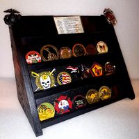
military and first responder challenge coin holder
...option to print long rows for larger printers, or smaller clip together pieces for smaller printers. the sides are...
3d_export
$5

guitar
...strings you can scale the object to make it smaller or larger. then after printing stick the two parts...
3d_export
$5
light switch
...poly and useful as an arch vis or game asset.<br>smaller screws can be used for games.<br>made in...
3d_export
$5

camera spinner 360
...this model. and it can not re scale to smaller one. it was a project that never used, so...
3d_ocean
$3
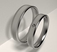
Engagement Rings
...rings. a bigger one without a diamond and a smaller ring with a diamond. polycount: 7200 faces...
Big
3ddd
$1

Big Ben
...big ben
3ddd
big ben , часы
часы moooi - big ben
by marcel wanders
3d_export
$5

Sexy big
...sexy big
3dexport
sexy big
3d_export
$5
big sword
...big sword
3dexport
it is a big sword, with a designe
turbosquid
$5
Big
... available on turbo squid, the world's leading provider of digital 3d models for visualization, films, television, and games.
turbosquid
$1
big
... available on turbo squid, the world's leading provider of digital 3d models for visualization, films, television, and games.
3d_export
$5
big monster
...big monster
3dexport
big monster 3d model printing
3ddd
$1
Kioto BIG
...kioto big
3ddd
itre , kioto
kioto big . itre
3d_ocean
$25

Big Bag
...the files are designed with clean topology, so are easy to edit & customize. there are 4 versions of files that are provid...
3ddd
$1
BIG BOB
...
version: 2014
preview: no
units: millimeters
polys: 391984
model parts: 20
render: v-ray
formats: 3ds max 2014, obj
design_connected
$13
Big Table
...big table
designconnected
bonaldo big table computer generated 3d model. designed by gilles, alain.
Completed
turbosquid
$35
complete plan
...quid
royalty free 3d model complete plan for download as max on turbosquid: 3d models for games, architecture, videos. (1221693)
turbosquid
$10
COMPLETE WASHROOM
...
royalty free 3d model complete washroom for download as max on turbosquid: 3d models for games, architecture, videos. (1413853)
turbosquid
$1
Complete Office
...id
royalty free 3d model complete office for download as max on turbosquid: 3d models for games, architecture, videos. (1323641)
vizpark
$509

VP COMPLETE
...e is the ultimate collection of 3d archviz assets, including 900 3d models, 50 hdris, 100 tileable textures and pattern software.
turbosquid
$15
excercise complete
... available on turbo squid, the world's leading provider of digital 3d models for visualization, films, television, and games.
turbosquid
$1
complete cabinet
... available on turbo squid, the world's leading provider of digital 3d models for visualization, films, television, and games.
turbosquid
free

complete Desk.lwo
... available on turbo squid, the world's leading provider of digital 3d models for visualization, films, television, and games.
3d_export
$5
Complete Wall Pack
...complete wall pack
3dexport
a complete set of 14 walls
3d_ocean
$12

Complete Model
... any other purpose. model includes, tree, street light, bench with urn, horse model. total poly and verts are 282,036 and 334,...
turbosquid
$80

sasuke complete susanoo
...oyalty free 3d model sasuke complete susanoo for download as on turbosquid: 3d models for games, architecture, videos. (1693376)
Printer
archibase_planet
free
Printer
...inter
archibase planet
printer laser printer pc equipment
printer n120614 - 3d model (*.gsm+*.3ds) for interior 3d visualization.
archibase_planet
free
Printer
...rchibase planet
laser printer office equipment computer equipment
printer - 3d model (*.gsm+*.3ds) for interior 3d visualization.
turbosquid
$100
Printer
...er
turbosquid
royalty free 3d model printer for download as on turbosquid: 3d models for games, architecture, videos. (1487819)
turbosquid
$3
Printer
...turbosquid
royalty free 3d model printer for download as max on turbosquid: 3d models for games, architecture, videos. (1670230)
turbosquid
$1
printer
...turbosquid
royalty free 3d model printer for download as max on turbosquid: 3d models for games, architecture, videos. (1595546)
turbosquid
$1
printer
...turbosquid
royalty free 3d model printer for download as max on turbosquid: 3d models for games, architecture, videos. (1595105)
turbosquid
$10
Printer
...id
royalty free 3d model printer for download as max and 3dm on turbosquid: 3d models for games, architecture, videos. (1607146)
turbosquid
$7
Printer
...royalty free 3d model printer for download as ma, ma, and obj on turbosquid: 3d models for games, architecture, videos. (1644580)
turbosquid
$30
Printer
... available on turbo squid, the world's leading provider of digital 3d models for visualization, films, television, and games.
turbosquid
$20
Printer
... available on turbo squid, the world's leading provider of digital 3d models for visualization, films, television, and games.
Version
3ddd
$1
Diamond version
...nd , version , ванна
visionnaire - diamond bath
turbosquid
$50
LibraryMini Version
...free 3d model librarymini version for download as max and jpg on turbosquid: 3d models for games, architecture, videos. (1617724)
design_connected
$34
Barocco Version 01
...barocco version 01
designconnected
zanotta barocco version 01 computer generated 3d model. designed by progetti, emaf.
design_connected
$27

Barocco Version 02
...barocco version 02
designconnected
zanotta barocco version 02 computer generated 3d model. designed by progetti, emaf.
turbosquid
free
![Door [2 versions]](/t/13243146.jpg)
Door [2 versions]
...rbosquid
free 3d model door [2 versions] for download as fbx on turbosquid: 3d models for games, architecture, videos. (1223985)
turbosquid
$2
seat version 0.1
...
royalty free 3d model seat version 0.1 for download as blend on turbosquid: 3d models for games, architecture, videos. (1432653)
turbosquid
$12
Chip Version 03
...lty free 3d model chip version 03 for download as c4d and fbx on turbosquid: 3d models for games, architecture, videos. (1241145)
3d_export
$10

magnolia grandiflora mature version
...magnolia grandiflora mature version
3dexport
magnolia grandiflora mature version
3d_export
$8
room assets and voxel version
...room assets and voxel version
3dexport
room assets and voxel version
turbosquid
$35

Zil Civilian version
... model zil civilian version for download as cgf, fbx, and obj on turbosquid: 3d models for games, architecture, videos. (1639420)