Thingiverse
Tinker-Friendly LACK Enclosure by zuspiel
by Thingiverse
Last crawled date: 4 years, 4 months ago
Edit: Added comments from IWannaMakeStuffEdit: Added additional pics of wiring and more info on hingesEdit: Added link to new RPi fanEdit: Added link to new RPi buck converterEdit: Added link to drill jig for leg extensionsEdit: Added link to Jure's filter stackEdit: Added taller upper leg for a total height of 95.3mmEdit: Added taller upper leg for a total height of 100.3mm
Design Philosophy
Let's face it: If you bought a 3D printer, you like to tinker. You can't help yourself and are constantly making improvements (and "improvements") to all kinds of things. That means an enclosure for the printer will be upgraded constantly. Therefore, I wanted a design that enables that. Primary design goals were
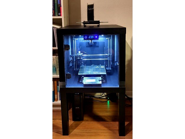
Sleek exterior. Basically a smooth cube all the way around.
Clean looking interior
Simple, fast, and full access to the printer within.
Easy to "mod" down the road
Spend money sensibly
Design Ideas
Entire top needs to be removable
Mount all electronics (basically) out of sight on the inside top
Inset, flush walls and door
Reconfigurable wiring
External 12V power supply to avoid dealing with mains voltages
So I started with two Ikea Lack tables ($16 total) like many others and went from there. I tried to keep the rest of the costs down but didn't want to cut corners in terms of features or looks.
Leg Extensions
The Lack tables are not tall enough to fit a printer comfortably, so extensions are necessary. I wanted the ultimate in servicability, so what better way than making the entire top come off? Easiest way was to design two piece leg extensions. The cone design makes it trivial to assemble and it's plenty sturdy. I stood on one of them which did not hurt it. Was contemplating some sort of locking mechanism to lock the top down but it's not really necessary. The extensions use hidden screws and the corners are even rounded to match the radius of the Lack legs.
The whole top can be lifted off after disconnecting the USB cable to the Rambo and unplugging the 12V supply to the top of the enclosure. Takes less than 10 seconds and you have full access to both the printer and all the enclosure bits. For further access, one or more of the side panels can then also be unscrewed.
The F360 archive contains the complete parametric design. Select "Change Parameters" and you can adjust the design at will. See screenshot. Turning the "Analysis" section on and off toggles the cut planes, FYI.
The STLs are sized for a 50.3mm extension. It's that value because I thought it would make it square. Except I didn't account for the fact that the legs are slightly inset... ;-)
For much easier mounting of the extensions, print out this great jig by lukefeil.
Side and Rear Walls
While transparent walls look cool, they have a couple of disadvantages
Heat insulation
Price
Ease of working with them
I went cheap(ish) and easy using 6mm thick "foamed" PVC
Easy to work with. Can cut nicely with a jigsaw using a PVC blade. Trivial to screw into. Fairly sturdy, one could easily mount (lightish) things to them if one wanted.
They are held in place from the inside with four printed brackets each (F360 "Small Parts", "Panel Bracket.stl"). The brackets are thicker on one side to allow me to use the screws I had laying around. The screws are small sheet metal screws and have nice big heads. Plus they are black... I used them throughout.
It's useful to make a little jig before drilling the holes. Way easier than measuring.
I used cheap foam insulation tape to seal the walls, sticking the tape to the legs so the panes can be removed while leaving the tape in place.
Door:
Used 3mm acrylic ("Plexiglass") for this.
Hadn't worked much with acrylic in the past but had sufficient respect so I didn't botch it completely. Tried the "score and break" method first but I guess I wasn't patient (deep) enough with the scoring. Ended up doing rough cuts with the same PVC blade in a jigsaw and then sanded it down using a layered sandpaper wheel in an angle grinder. I used an aluminum angle as a guide during the sanding.
Went to a local hardware store to see what hinge designs were available. I had contemplated printing some but didn't want them on the outside. The mechanism for inside hinges is a bit involved, so buying them seemed like a better option. I found a style that worked well with two exceptions: Looks and very strong springs. The looks were easy to hide behind little printed cover plates (F360 "Small Parts" archive, "Hinge Cover.stl"). The spring and its casing can actually be completely removed. Since it's nice to have the open door hold open by itself, I instead decided to replace the spring with a much weaker one I had laying around. Pardon the C-clips on the back of the hinges. I didn't have any regular black screws ;-) Incidentally, those screws are the only externally visible ones on the whole enclosure. Avoiding them seemed more trouble than it was worth.
Edit: I believe these are the hinges I picked up: http://www.homedepot.com/p/Liberty-90-Degree-Surface-Mount-Hidden-Spring-Hinge-1-Pair-H01068C-UC-C5/100176398
The cylinder in the center of the hinge can be removed. The spring is hidden inside.
Edit:
Comment from IWannaMakeStuff:
A couple of hardware/parts notes: The Home Depot hinge you linked does indeed work as designed, but note it does not match the footprint of the hinge cover file you included without modification. To match I printed X at 44mm instead of 48mm. Y (48mm) and Z (0.8mm) remained as they were and were fine. However, make sure you measure the screw locations carefully as they don't line up where you might expect. Instead of sheet metal screws, I used M3 x 12mm screws and nuts, though I'll probably upgrade to lock nuts when I replenish my supply.
For the handle, I used this with two M4 x 16mm screws and lock nuts: http://www.thingiverse.com/thing:36465
The door is held closed by a magnetic pusher from my parts bin. Used epoxy to glue a washer to the door for the magnet to grab.
Edit: Comment from IWannaMakeStuff:
I like your hinges but I prefer an alternative door handle, so I've created a magnetic bracket that can be used with different handle styles. You can view it at the link below. Please feel free to add it to your description if you find it useful. :-)http://www.thingiverse.com/thing:2186895
To seal the sides and top of the door, I used this automotive rubber casket. One could use it all over the place but it's significantly more expensive than the foam tape. Looks the part and works well.
Filament Guide in Top Surface
I used a scaled down version of a Thing I found, but I appear to have lost the original link. Sorry...
Front Control Panel
This is behind the door since it looks cleaner and the buttons don't really need to be accessible with the door closed. Files are called "Thermometer_Power_Switch_Box".
Power button - Turns on lights and fume control fan (the Pi is constant on).
Fan override button - Turns on all exhaust fans, indicates when exhaust fans are on (either automatically via the controller or through the override button)
Both button are hooked up via these pre-wired plugs. I could have soldered the wires on, too...
Temperature Display - Cheap and nice looking. Not much to say. The sensor is right behind the control panel.
Fume control
The initial reason for building this enclosure was temp control for ABS. I wanted to handle the ABS fumes internally to keep the enclosure location flexible. I found this Thing
Edit: Jure has meanwhile designed a better looking filter sandwich: http://www.thingiverse.com/thing:2105113
Does most of what I needed and could be tucked away in the back of the enclosure. I then went a step further and wanted a bit of convection in the enclosure. So I added the redirector (OSCAD, "CleanAirRedirector"). The HEPA filter restricts the flow considerably, so only a gentle breeze is coming out of it. We'll see how well it goes. The redirector obviously needs internal support when printing. It only redirects 2/3 of the clean output, increasing the chances that the exhaust fans pick up clean air.
Link to fan
It's a bit loud for my taste, so I may change it down the road. The fan currently runs whenever the lights are on, but I'll automate turning it on only while printing via the Pi in the future.
The whole thing is held to the top via four small brackets, sized to make it level (OSCAD, "FumeBrackets").
Exhaust
I'm using 3 small, quiet fans. Main reason I went for three fans is that I could be flexible in how many fans are controlled by the temp controller. In the grand scheme of things, that was probably more flexibility than needed but oh well. Bracket designed in OSCAD. Use short M3 screws to hold them in.
Temperature control is provided by this little temp controller.
A friend just found this alternative, which looks awesome. It's powered by mains voltage but should still be able to switch a 12V fan
The temperature sensor is positioned between the HEPA filter and the exhaust fans.
F360 "Small Parts - Temperature Controller Bracket", "TempControllerBracket.stl" and "TempSensorBracket.stl".
Air Intakes
I put two intake vents through the bottom table. The holes are located underneath the Z axis steppers (F360 "Small Parts", "Vent Cover.stl"). Being on the bottom, they can remain open all the time without loosing hot air.
Printer Padding
I had some 1/2 inch Dynaliner closed cell foam lying around. Makes a perfect cushion for the printer and sticks to the bottom.
Raspberry Pi
I used a Pi 3 since it has built-in wifi.
For the enclosure, this thing worked well.
And I used this fan.Edit: Don't get this fan! Mine became very loud recently. I replaced it with this, using this adapter. The adapter isn't perfect, some of the walls are too thin to print, but it works. Will probably remix the top of the case to take the 40 mm fan directly.
And these heat sinks.
The fan is only running when the main power switch is on. No need to cool the Pi when nothing else is running.
The camera is the current PiCam.
and held in this case.
The case is not perfect (I used tape to hold it together...) but it's ok. I may design my own down the road.
To refocus the camera, this thing comes in handy.
The longer camera cable is this one.
Power comes from this.
However, there's a problem: I get undervoltage warnings on the Pi if a display is connected. I played with multiple USB adapters and see that issue with all the ones I tried. This may be an alternative, but I'm still not sure it'll be good enough.
Ideally, I want a 12V to 5.1V @ 2-3A solution that doesn't break the bank. Anybody have any ideas?
Edit: This buck converter is what I'm running now. The same board is also available at Amazon (thanks for the link in the comments).
Wiring
The entire gear runs from a single, external 12V power supply. That allows for safe wiring without having to worry about mains voltage running around. I didn't solder anything since that would just make it harder to change things down the road. Those wire clamps rule. They are used all over the place in Europe so I typically pick up a bunch whenever I'm back visiting. They can also be sourced in the US, though. The pics should be able to serve as a wiring diagram. ;-)
The zip tie anchors were great to keep everything neat. And they print without support.
Future improvements
Two focus areas: Safety and automation. I already have a 110V relay box and a smoke detector for the Pi
This will give the Pi control over the power to the printer, allowing it to shut things off if stuff starts smelling iffy. Octopi allows fairly simple integration of additional functionality, so I plan on adding an enclosure temp sensor and control of the fans via a relay board. There are many other things one could add...
Final thoughts
If I had to do it again, I'd probably use 20x20 extrusions. In the end, the Lack tables don't save that much money and most of the cost is elsewhere, anyway.
Design Philosophy
Let's face it: If you bought a 3D printer, you like to tinker. You can't help yourself and are constantly making improvements (and "improvements") to all kinds of things. That means an enclosure for the printer will be upgraded constantly. Therefore, I wanted a design that enables that. Primary design goals were
Sleek exterior. Basically a smooth cube all the way around.
Clean looking interior
Simple, fast, and full access to the printer within.
Easy to "mod" down the road
Spend money sensibly
Design Ideas
Entire top needs to be removable
Mount all electronics (basically) out of sight on the inside top
Inset, flush walls and door
Reconfigurable wiring
External 12V power supply to avoid dealing with mains voltages
So I started with two Ikea Lack tables ($16 total) like many others and went from there. I tried to keep the rest of the costs down but didn't want to cut corners in terms of features or looks.
Leg Extensions
The Lack tables are not tall enough to fit a printer comfortably, so extensions are necessary. I wanted the ultimate in servicability, so what better way than making the entire top come off? Easiest way was to design two piece leg extensions. The cone design makes it trivial to assemble and it's plenty sturdy. I stood on one of them which did not hurt it. Was contemplating some sort of locking mechanism to lock the top down but it's not really necessary. The extensions use hidden screws and the corners are even rounded to match the radius of the Lack legs.
The whole top can be lifted off after disconnecting the USB cable to the Rambo and unplugging the 12V supply to the top of the enclosure. Takes less than 10 seconds and you have full access to both the printer and all the enclosure bits. For further access, one or more of the side panels can then also be unscrewed.
The F360 archive contains the complete parametric design. Select "Change Parameters" and you can adjust the design at will. See screenshot. Turning the "Analysis" section on and off toggles the cut planes, FYI.
The STLs are sized for a 50.3mm extension. It's that value because I thought it would make it square. Except I didn't account for the fact that the legs are slightly inset... ;-)
For much easier mounting of the extensions, print out this great jig by lukefeil.
Side and Rear Walls
While transparent walls look cool, they have a couple of disadvantages
Heat insulation
Price
Ease of working with them
I went cheap(ish) and easy using 6mm thick "foamed" PVC
Easy to work with. Can cut nicely with a jigsaw using a PVC blade. Trivial to screw into. Fairly sturdy, one could easily mount (lightish) things to them if one wanted.
They are held in place from the inside with four printed brackets each (F360 "Small Parts", "Panel Bracket.stl"). The brackets are thicker on one side to allow me to use the screws I had laying around. The screws are small sheet metal screws and have nice big heads. Plus they are black... I used them throughout.
It's useful to make a little jig before drilling the holes. Way easier than measuring.
I used cheap foam insulation tape to seal the walls, sticking the tape to the legs so the panes can be removed while leaving the tape in place.
Door:
Used 3mm acrylic ("Plexiglass") for this.
Hadn't worked much with acrylic in the past but had sufficient respect so I didn't botch it completely. Tried the "score and break" method first but I guess I wasn't patient (deep) enough with the scoring. Ended up doing rough cuts with the same PVC blade in a jigsaw and then sanded it down using a layered sandpaper wheel in an angle grinder. I used an aluminum angle as a guide during the sanding.
Went to a local hardware store to see what hinge designs were available. I had contemplated printing some but didn't want them on the outside. The mechanism for inside hinges is a bit involved, so buying them seemed like a better option. I found a style that worked well with two exceptions: Looks and very strong springs. The looks were easy to hide behind little printed cover plates (F360 "Small Parts" archive, "Hinge Cover.stl"). The spring and its casing can actually be completely removed. Since it's nice to have the open door hold open by itself, I instead decided to replace the spring with a much weaker one I had laying around. Pardon the C-clips on the back of the hinges. I didn't have any regular black screws ;-) Incidentally, those screws are the only externally visible ones on the whole enclosure. Avoiding them seemed more trouble than it was worth.
Edit: I believe these are the hinges I picked up: http://www.homedepot.com/p/Liberty-90-Degree-Surface-Mount-Hidden-Spring-Hinge-1-Pair-H01068C-UC-C5/100176398
The cylinder in the center of the hinge can be removed. The spring is hidden inside.
Edit:
Comment from IWannaMakeStuff:
A couple of hardware/parts notes: The Home Depot hinge you linked does indeed work as designed, but note it does not match the footprint of the hinge cover file you included without modification. To match I printed X at 44mm instead of 48mm. Y (48mm) and Z (0.8mm) remained as they were and were fine. However, make sure you measure the screw locations carefully as they don't line up where you might expect. Instead of sheet metal screws, I used M3 x 12mm screws and nuts, though I'll probably upgrade to lock nuts when I replenish my supply.
For the handle, I used this with two M4 x 16mm screws and lock nuts: http://www.thingiverse.com/thing:36465
The door is held closed by a magnetic pusher from my parts bin. Used epoxy to glue a washer to the door for the magnet to grab.
Edit: Comment from IWannaMakeStuff:
I like your hinges but I prefer an alternative door handle, so I've created a magnetic bracket that can be used with different handle styles. You can view it at the link below. Please feel free to add it to your description if you find it useful. :-)http://www.thingiverse.com/thing:2186895
To seal the sides and top of the door, I used this automotive rubber casket. One could use it all over the place but it's significantly more expensive than the foam tape. Looks the part and works well.
Filament Guide in Top Surface
I used a scaled down version of a Thing I found, but I appear to have lost the original link. Sorry...
Front Control Panel
This is behind the door since it looks cleaner and the buttons don't really need to be accessible with the door closed. Files are called "Thermometer_Power_Switch_Box".
Power button - Turns on lights and fume control fan (the Pi is constant on).
Fan override button - Turns on all exhaust fans, indicates when exhaust fans are on (either automatically via the controller or through the override button)
Both button are hooked up via these pre-wired plugs. I could have soldered the wires on, too...
Temperature Display - Cheap and nice looking. Not much to say. The sensor is right behind the control panel.
Fume control
The initial reason for building this enclosure was temp control for ABS. I wanted to handle the ABS fumes internally to keep the enclosure location flexible. I found this Thing
Edit: Jure has meanwhile designed a better looking filter sandwich: http://www.thingiverse.com/thing:2105113
Does most of what I needed and could be tucked away in the back of the enclosure. I then went a step further and wanted a bit of convection in the enclosure. So I added the redirector (OSCAD, "CleanAirRedirector"). The HEPA filter restricts the flow considerably, so only a gentle breeze is coming out of it. We'll see how well it goes. The redirector obviously needs internal support when printing. It only redirects 2/3 of the clean output, increasing the chances that the exhaust fans pick up clean air.
Link to fan
It's a bit loud for my taste, so I may change it down the road. The fan currently runs whenever the lights are on, but I'll automate turning it on only while printing via the Pi in the future.
The whole thing is held to the top via four small brackets, sized to make it level (OSCAD, "FumeBrackets").
Exhaust
I'm using 3 small, quiet fans. Main reason I went for three fans is that I could be flexible in how many fans are controlled by the temp controller. In the grand scheme of things, that was probably more flexibility than needed but oh well. Bracket designed in OSCAD. Use short M3 screws to hold them in.
Temperature control is provided by this little temp controller.
A friend just found this alternative, which looks awesome. It's powered by mains voltage but should still be able to switch a 12V fan
The temperature sensor is positioned between the HEPA filter and the exhaust fans.
F360 "Small Parts - Temperature Controller Bracket", "TempControllerBracket.stl" and "TempSensorBracket.stl".
Air Intakes
I put two intake vents through the bottom table. The holes are located underneath the Z axis steppers (F360 "Small Parts", "Vent Cover.stl"). Being on the bottom, they can remain open all the time without loosing hot air.
Printer Padding
I had some 1/2 inch Dynaliner closed cell foam lying around. Makes a perfect cushion for the printer and sticks to the bottom.
Raspberry Pi
I used a Pi 3 since it has built-in wifi.
For the enclosure, this thing worked well.
And I used this fan.Edit: Don't get this fan! Mine became very loud recently. I replaced it with this, using this adapter. The adapter isn't perfect, some of the walls are too thin to print, but it works. Will probably remix the top of the case to take the 40 mm fan directly.
And these heat sinks.
The fan is only running when the main power switch is on. No need to cool the Pi when nothing else is running.
The camera is the current PiCam.
and held in this case.
The case is not perfect (I used tape to hold it together...) but it's ok. I may design my own down the road.
To refocus the camera, this thing comes in handy.
The longer camera cable is this one.
Power comes from this.
However, there's a problem: I get undervoltage warnings on the Pi if a display is connected. I played with multiple USB adapters and see that issue with all the ones I tried. This may be an alternative, but I'm still not sure it'll be good enough.
Ideally, I want a 12V to 5.1V @ 2-3A solution that doesn't break the bank. Anybody have any ideas?
Edit: This buck converter is what I'm running now. The same board is also available at Amazon (thanks for the link in the comments).
Wiring
The entire gear runs from a single, external 12V power supply. That allows for safe wiring without having to worry about mains voltage running around. I didn't solder anything since that would just make it harder to change things down the road. Those wire clamps rule. They are used all over the place in Europe so I typically pick up a bunch whenever I'm back visiting. They can also be sourced in the US, though. The pics should be able to serve as a wiring diagram. ;-)
The zip tie anchors were great to keep everything neat. And they print without support.
Future improvements
Two focus areas: Safety and automation. I already have a 110V relay box and a smoke detector for the Pi
This will give the Pi control over the power to the printer, allowing it to shut things off if stuff starts smelling iffy. Octopi allows fairly simple integration of additional functionality, so I plan on adding an enclosure temp sensor and control of the fans via a relay board. There are many other things one could add...
Final thoughts
If I had to do it again, I'd probably use 20x20 extrusions. In the end, the Lack tables don't save that much money and most of the cost is elsewhere, anyway.