Thingiverse
Theremin by elkayem
by Thingiverse
Last crawled date: 3 years ago
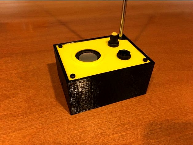
This is a 3D printed case for a simple, pitch only theremin design known as the "Thierrymin", named after its designer Thierry Frenkel. The schematic and instructions can be found over at Theremin World at http://www.thereminworld.com/Forums/T/29231/my-new-year-gift-to-tw-a-new-theremin-circuit?Page=0.
I have included Thierry's schematic on this page, but strongly encourage you to head over to the thread linked above for more assembly and tuning instructions. This is a really simple circuit to assemble, and a lot of fun to play with.
I have also added a small 2W speaker and an LM386 amplifier. I have also included a schematic showing how this amplifier is wired.
In addition to the parts Thierry lists on the schematic, you will also need the following parts for use with this 3D printed case:
50mm x 80mm breadboard. I used the one from BusBoard (model PAD1), available from Mouser or Digikey
10K 16mm rotary potentiometer
36mm diameter 8 Ohm speaker (see picture)
1/4" Mono Switched Phone Connector
Round rocker switch (20mm diam hole)
LM386 amplifier
4mm banana socket jack (or similar) for grounding connector
9V battery connector
50cm, 6mm diam telescopic antenna, with 3mm thread. I've included a picture. Mine was actually 47cm from uxcell, and worked just fine.
12mm M3 bolts and nuts
Side-facing variable capacitor (see below)
The schematic calls for a 4-22 pF variable capacitor. I recommend using a capacitor that faces to the side, so it can be adjusted after the box is closed. The case design includes a hole on the left side, and the capacitor will need to be aligned with this hole. I used the Sprague Goodman GYD40000 3.5 - 40 pF capacitor, available at Mouser, which did the trick. If using the same capacitor, place it in the upper left corner of the breadboard, facing left, with the center lined up with the 5th row from the top of the board (see photo).
This unit is designed to be powered off of a 9V battery. That said, it works best when grounded. If you are connecting to an external amplifier using the 1/4" jack, it is likely that the shield is already grounded. However, if you are using the speaker on the unit, you may find that a grounded connection gets better performance. In the photo, you will see a green banana jack on the back for this purpose. I connected that to a modified wall plug with only the ground connected.
The case needs to be printed with internal supports, due to the antenna mount. M3 nuts hold the lid in place. To insert the nuts, use a long M3 bold through the hole in the case, thread the nut into the bolt, and pull up (or tighten). They should be held in place with friction until the lid is installed.
Last, the speaker can be held in place with hot glue (see photo). Enjoy!
Similar models
thingiverse
free

BreadBoard Speaker by StefTheo
...ation.
i print it in translucid petg, infill 20% honeycomb, it's nice !
changes :
add little holes to dismount the breadboard
thingiverse
free

Breadboard Speaker Amplifier by CaptObvious
... console.
the small tab fits into the slot with a friction fit, holding the speaker in place. also see my breadboard battery box.
thingiverse
free

Jamming 9V by Lionshead
... switch, a 9v connector, and a screw to secure the back cover. i use a heat-set, brass m2 threaded insert with a flat-head screw.
thingiverse
free

ZK-502C 2x50W Bluetooth amplifier Case by Reddrago789
...es the originally provided bottom plate and 4 m2 screws. i tapped the holes in the pcb supports, be sure not to overtighten them.
grabcad
free

speaker connector
...r speakers, female, for mounting on amplifier cases/housing. assembly file. exact model, 9.5mm dia hole required on the case/box.
thingiverse
free

Simple 3W speaker by Ceserik
...it.ly/2yf133v
using 18650 battery
instead of nuts put these m3 brass inserts in holes in "front" https://bit.ly/2xveaya
3dwarehouse
free

LM386 Audio Amp schematics
... sketch up #amplifier #audio #audio_amp #audio_wiring #circuitry #circuits #diagram #lm386 #schematics #wiring #wiring_schematics
thingiverse
free

15W Stereo Amplifier Case by ctheroux
...t main web page is:http://www.ctheroux.com/15w-stereo-amplifier-case/.
you can request the source files on the page listed above.
grabcad
free

LM386 Mini Micro Audio Amplifier Module
...12v lm386 mini micro audio amplifier module ,used in my project,for driving my speakers,
project address: https://ilikeilucky.com
thingiverse
free

Vibration Micro Motor Case by codeholic
...codeholic thingiverse a case for a vibration micro motor (similar to z4tl2b124064x) and a jst-ph 2-pin connector. there is...
Elkayem
thingiverse
free

Pan Tilt mount for ProtoTank by elkayem
...unts out there on thingiverse, for example, http://www.thingiverse.com/thing:350229 and http://www.thingiverse.com/thing:1242570.
thingiverse
free

ESP Nixie Clock (ESP8266 CPU) by elkayem
...ler, allowing it to automatically sync its time to nist over wifi, and 2) it features a 3d printed frame and hand-solderable pcb.
thingiverse
free

Breadboard Wire Bending Tool by elkayem
...im i found on thingiverse. i really liked zim's design, but had to make some adjustments to get the 0.1" spacing right.
thingiverse
free

Arcade Controller by elkayem
...#39;ve also included the sketchup file, in case modifications are required for slightly different button and joystick dimensions.
thingiverse
free

Papilio One Logic Analyzer Case by elkayem
...nted with supports to prevent the pin cutouts from sagging. the papilio should be mounted to the base using four m3 x 8mm bolts.
thingiverse
free

MIDI to CV Converter by elkayem
...hat your printer is disabling the stepper motors after pausing, you may need to insert m84 s0 at the start of the g-code. i did.)
thingiverse
free

Eurorack CV to Midi 6HP face
...midi to cv converter is found on his github, https://github.com/elkayemmidi2cv ...
thingiverse
free

Water Turbine School Science Experiment by elkayem
...ngiverse.com/thing:16627. we drove a 3w rgb led in series with a 3.3 ohm resistor (wear your sunglasses, these leds are bright!)
thingiverse
free

18mm Induction Z Probe Mount for E3D v6 Integrated Fan Support by elkayem by thebabymaker
...j18a3-8-z/bx dc 6-36v npn. it only has space for the nut at the top and not the washer, i used the washer and nut on the bottom.
Theremin
thingiverse
free

Open Theremin UNO Laser Housing by gaudi
... the cv jack and the usb and power plug of the arduino.
for more information on the theremin shield see:www.gaudi.ch/opentheremin
thingiverse
free

Theremin Coil Body by tamberg
...sed by the most experienced russian classical theremin builder lev koroliov."
http://asmir.theremin.ru/coil_construction.htm
thingiverse
free

Snooker ball marker by Theremin
...snooker ball marker by theremin
thingiverse
a ball marker suited for 52.4mm snooker balls.
thingiverse
free

Madlab Junior Theremin 3D printed case by 3Dresearcher
...esearcher
thingiverse
een specifieke case voor de madlab junior theremin.
gebruik : https://www.youtube.com/watch?v=mgom5xl7bao
thingiverse
free

3D Printed Case for Open Source Theremin by gaudi
... just as the original theremin.
for source files and instructions or to buy a complete kit see:http://www.gaudi.ch/opentheremin
thingiverse
free

Propeller balancer by Theremin
...14927
balance your props!
you'll just need some cubic 5mm strong magnets and a bolt and nut for the table clamp part (m5)
thingiverse
free

LaserCut Open Theremin V3 Housing by PablodMM
...b (in pinterest, not a reliable source to credit the author https://de.pinterest.com/pin/331014641335771182/)
share and enjoy :-)
thingiverse
free

LaserCut Open Theremin V3 Housing wider sides no picture by joshielevy
...merican standard 1/4" nuts. also resized the parts in the box itself to better fit the open theremin v3 plus the arduino uno
thingiverse
free

Open Theremin v3 Top Panel Annotated by ACh
...open theremin v3 top panel annotated by ach
thingiverse
top panel with text.
recommended nozzle diam 0.3 mm or finer.
thingiverse
free

Binaural mic adapter for ear. by Theremin
...d then make it with rubber in order to create a binaural microphone. this stl is for the piece that holds the microphone capsule.