Thingiverse
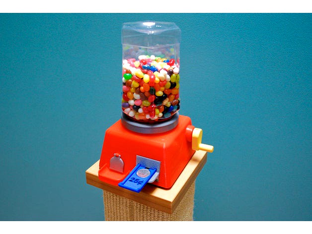
The Coin Slide Operated Jelly Bean Machine by sthone
by Thingiverse
Last crawled date: 3 years ago
This started out as a simple project to test out printing some worm gears. I started designing a simple base to hold the gears so I could test them and I just happened to be snacking on jelly beans and thought "I should make a jelly bean dispenser out of these."... then about halfway into it I thought "man this should be coin operated like some of those other 3D printed candy machines".... then "Maybe it should be different though" so I decided to design and incorporate a coin slide operated mechanism... well after all that this snowballed into the "The Coin Slide Operated Jelly Bean Machine."
I designed this and printed this over two years ago so I don't exactly remember much of my thought process while designing it I just know I kept adding to the design as I went so I'm sure there was much easier ways to accomplish things. (there are some design flaws.)
Anyway.... This probably isn't for the faint of heart and I doubt anyone is crazy enough to try printing this but I still thought I'd post it because someone might be able to use parts of it (the coin slide mechanism?) or maybe at least get ideas from it.
The whole thing was designed to work with a 40 oz jar from Gimbals Fine Candies Gourmet Jelly Beans. that I found on Amazon.
If your crazy enough to try printing one of these there are some more diagrams here and I tried to do some quick assembly instructions below but your going to have to figure out somethings on your own especially things like sourcing the correct springs. You will have to rotate some of the STL's for printing too I forgot to orientate them before uploading them and I'm sure some parts will need fitting before assembly. Oversized jelly beans can jam up the works too, sometimes they can be cut in half by the tab on the cover and they will need to be cleaned out if that happens. Like I said I designed this a few years ago so details are fuzzy but if you have questions I will try to answer them.
Assembly of the Base
Start by inserting the Worm_Gear into the Base.
Slide the Shaft_Plug onto the Worm_Gear_Shaft then Slide on the Shaft_Plug and then the Handle.
Screw on the Handle to the Shaft_Plug with a 4-40 x 3/8" Button Head Screw.
Drop the Spring and Ratchet_Stop into the square hole in the Base. (make sure the spring you use will stand upright.) The tallest point of the Ratchet_Stop should be toward the front of the Base.
Insert the Handle assembly into the hole aligning it into the Worm_Gear. Using a 4-40 x 1/2" socket head screw attach the Shaft Plug to the Base through the hole in the bottom of the Base.
Turn the handle clockwise (away from you) to check for Proper operation. (You may have to hold the Main_Gear down with your finger.)
Slide the Dispenser_Disk under the tab on the Cover and then place the Dispenser_Disk onto the shaft of the Main_Gear.
Attach the Cover to the Base with (4) 2-56 x 1/4" flat head screws. (you will have to move the Dispenser_Disk around to screw in the screws.
Next attach the Dispenser_Disk to the Main_Shaft with a 8-32 x 2 1/4" long flat head screw.
Once again turn the handle clockwise (away from you) to check for Proper operation. The Dispenser_Disk should turn counter clockwise.
Assembly of the Coin Slide
Insert the Coin_Slide into the Slide_Block
Screw in a 2-56 x 3/8" button head screw into the single larger hole in the bottom of the Slide_Block. (Only tighten the screw enough so the Coin_Slide can not be removed from the Sidle_Block but is still free to move in and out.
Screw a 6-32" x 3/8" socket head cap screw into the Gear_Stop (it doesn't need to go in all the way and will be adjusted later.)
With the Coin_Slide pulled all the way out drop your Spring into the rear square hole. (the spring you use must stand up.)
Next a smaller spring is inserted into the hole that is inside the rear of that square hole in the Slide_Block.
This spring must be compressed while inserting in the Gear_Stop. You also have to make sure the bottom spring stays upright. (yes this can be a pain in the a$$)
After inserting the Gear_Stop secure it with a 4-40 x 1/2" flat head screw though the side of the Slide_Block.
Check the the Gear_Stop moves up and down while still wiggling front to back.
The other square hole in the top of the Slide_Block is for the Gear_Teeth_Stop. This is suppose to use a 2/56 socket head cap screw to keep the Main_Gear from turning until you pull the Coin_slide back out but is a design flaw and it tends to jam everything up so I do not use it.
Next insert the Lock_Block and secure with a 4-40 x 5/8" socket head screw.
Test the operation with and without a quarter. With a quarter in the Coin_Slide the screw in the top of the Gear_Stop should fully retract and be just below the top of the Slide_Block when the Coin_Slide is fully pressed in. (You still may need to adjust the later for proper fit with the Main_Gear.)
Final Assembly and Adjustment
Place a quarter int he Coin slide and push it all the way forward to retract the Gear Stop.
Insert the Coin Slide Assembly into the Base and align the holes and secure with (2) 6-32 x 1/2" flat head screws.
Pull the Coil Slide out then turn the Handle until in Locks in place. If it does not Lock place you need to remove the Coin Slide Assembly and adjust the screw in the top of the Gear Stop. Repeat the process until you find the sweet spot that will lock the handle. NEVER FORCE THE HANDLE ONCE IT LOCKS.
Retest the operation a few times to make sure everything is working correctly. Keep in mind without the Gear_Teeth_Stop you can continue to turn the handle as long as you want if the Coin Slide is left pressed in.
The Door_Hinge can be super glued to the base and the Door_Flap attached with a pin made out of something like a sewing pin.
Turn the Base upside down to screw on the Jar full of delicious jelly beans.
To keep people honest.... The Coin_Box can be secured with a 4-40 x 1/4" Flat head screw and the Jar Lock and be secured with a 4-40 x 1/2" button head screw and nut.
Enjoy...... and reap the profits.
UPDATE
4/13/18 - Added a 3 piece handle so the handle part will actually spin. Use a 4/40 socket head screw to assemble. (I have not test printed this yet)
Similar models
cults
free

The Coin Slide Operated Jelly Bean Machine
...t head screw and the jar lock and be secured with a 4-40 x 1/2" button head screw and nut.
enjoy...... and reap the profits.
thingiverse
free

Vileda head socket strenghtened by oaba
...es for the screws. and secure it on the side with screws.
i was printing it with 100 percent infill. to get the maximum strenght.
thingiverse
free

IC Pin Straightener by jeffthompson
...for straightening the legs of integrated circuits, based on similar tools. requires: 1x: 3d-printed parts 2x: #4-40 x 1.25"...
thingiverse
free

Universal Microscope Phone Adapter iPhone XS Plus
...ned to work on a printer without support. let me know if there are any issues.
this is arsenal's website:
arsenalproducts.com
grabcad
free

Machine Handle
...machine handle
grabcad
handle with 1/4" scree holes for attachment
includes 1/4-20 socket head screws
thingiverse
free

PowerSeeker 114EQ Dovetail Base Finder Scope Mount by shroppy
...ack the whole socket head cap screw out. the next time i have some out to play with i’ll try to take a photo to add to this post.
thingiverse
free

Spring Loaded CD Mount Tablet Holder by jmf
...ng around, trim as needed, i also used some ca on the pin to keep it from falling out.
this mount works great on a table top too.
thingiverse
free

MPCNC Universal Holder for Dual MK8 Extruders by pavel569
...e holder rail are sliding smoothly (but not loosely) in the main body. on the top are some holes and slots for a wire management.
thingiverse
free

Synta Shoe For Explore Scientific Handle by Greasydeal
.../4" socket head cap screws (i used 1" length in the pictures)
(2) 8-32 nuts
check out my site at www.dirtyastronomy.com
thingiverse
free

Ear Plug Pocket Case by WTF_Racing
...he case uses the pen spring and pin as a detent to keep the case closed or open. the cover snaps in to the detent in 4 positions.
Sthone
thingiverse
free

Wire Exits by sthone
...wire exits by sthone
thingiverse
computer wire exits for use with 3/4" plywood.
thingiverse
free

Motherboard Stand Off by sthone
...motherboard stand off by sthone
thingiverse
standoff for a mounting a motherboard to a flat surface.
thingiverse
free

External Hard Drive Mount by sthone
...e mount by sthone
thingiverse
this is a simple mount i used to mount an external hard drive (rosewill rx35-at-iu) under my desk.
thingiverse
free

Mini Crossbow by sthone - Remixed for springs by TH3D
...w.youtube.com/watch?v=b0uxetiqkje
get the iron sights / bolt holder here:https://www.thingiverse.com/thing:1021002
(just glue it)
thingiverse
free

Makergear M2 Extended Spool Arm by sthone
...thingiverse
extended spool holder for the makergear m2 printer.
this is a .95" lengthened version of the original holder.
thingiverse
free

Aerosol Straw Saver by sthone
... will save it (if it pops out of the nozzle) from shooting across the room and under that void that seems to exist in every shop.
thingiverse
free

Iron sights and bolt holder for sthone's crossbow by TH3D
...d bolt holder for sthone's crossbow by th3d
thingiverse
makes aiming easier, and also holds the arrow / bolt firmly in place
thingiverse
free

3D Printed Clock by sthone
...ent but everything else was printed on a makegear m2.
time lapse of it in action - https://www.youtube.com/watch?v=kcvprbovcnu
thingiverse
free

Insulin Bottle Holder by sthone
...m the light every time the refrigerator door is opened. not sure if it will prolong things but it keeps the bottle stable anyway.
thingiverse
free

Makergear M2 Single V4 Extruder Fan Shroud by sthone
...m2 single v4 extruder fan shroud by sthone
thingiverse
this is a simple fan shroud for the single v4 extruder on a makergear m2.
Jelly
turbosquid
$19

Jelly
...royalty free 3d model jelly for download as max, obj, and fbx on turbosquid: 3d models for games, architecture, videos. (1369280)
3d_export
free

jelly
...jelly
3dexport
my first model from blender
3d_export
$25

jelly fish jellyfish
...jelly fish jellyfish
3dexport
jelly fish jellyfish
3d_export
$25

jelly fish jellyfish
...jelly fish jellyfish
3dexport
jelly fish jellyfish
3d_ocean
$5

Red Jelly Monster
... jelly monster
3docean
blender crazy jelly monsters
a red jelly monster made with blender and rendered with cycles render engine.
turbosquid
$20

Jelly Cup
...rbosquid
royalty free 3d model jelly cup for download as max on turbosquid: 3d models for games, architecture, videos. (1388111)
turbosquid
$3

Jelly animated
...uid
royalty free 3d model jelly animated for download as c4d on turbosquid: 3d models for games, architecture, videos. (1384780)
turbosquid
$25

Jelly Fish
... available on turbo squid, the world's leading provider of digital 3d models for visualization, films, television, and games.
turbosquid
$10

Jelly Guy
... available on turbo squid, the world's leading provider of digital 3d models for visualization, films, television, and games.
turbosquid
$6

Jelly Rings
... available on turbo squid, the world's leading provider of digital 3d models for visualization, films, television, and games.
Bean
3d_ocean
$5

caffe bean
...ffe coffe bean coffee drink food hot lowpoly max particle particles systems textured
cafe bean vray render texture and backgraund
3d_export
$5

coffee beans
...coffee beans
3dexport
coffee beans
turbosquid
$1

bean
... available on turbo squid, the world's leading provider of digital 3d models for visualization, films, television, and games.
3ddd
$1

Bean bags
...n bags
3ddd
мешок , пуф , bean bag
кресло мешок
3d_ocean
$2

coffee bean
...fee bean
3docean
bean coffe coffee hot beverage
realistic model of cofee bean textured with hi rez maps ready for your projects .
3ddd
$1

Bean bag_Subberjean
...bean bag_subberjean
3ddd
кресло-мешок
bean bag, то бишь бескаркасное кресло.
3ddd
free

Bean
...bean
3ddd
фасоль
скульптура "фасоль"
3ddd
free

Coffee Beans
...coffee beans
3ddd
кофе , зерна
coffee beans
зёрна кофе
polys: 9630/1
3ddd
$1

Bean Bag Chair
... restoration , кресло мешок , мешок
кресло
design_connected
$18

Bean Desk
...bean desk
designconnected
ceccotti collezioni bean desk computer generated 3d model. designed by lazzeroni, roberto.
Coin
3d_ocean
$5

Coin
...ee coin 5 rupee coin cent coin india indian coin low poly low poly indian coin model old paisa rupee texture
low poly indian coin
3d_export
$5

coins
...coins
3dexport
coins
3d_ocean
$2

Coin
...coin
3docean
coin dollar euro gold money pay payment silver
one coin side engraving “in coins we trust”
archibase_planet
free

Coin
...coin
archibase planet
coin one dime ten-cent coin dime
coin 4 - 3d model (*.3ds) for interior 3d visualization.
archibase_planet
free

Coin
...coin
archibase planet
coin one dime dime ten-cent coin
coin 5 - 3d model (*.3ds) for interior 3d visualization.
archibase_planet
free

Coin
...coin
archibase planet
coin nickel five cents five-cent coin
coin 3 - 3d model (*.3ds) for interior 3d visualization.
archibase_planet
free

Coin
...coin
archibase planet
coin dollar one dollar dollar coin silver dollar
coin 1 - 3d model (*.3ds) for interior 3d visualization.
archibase_planet
free

Coin
...coin
archibase planet
coin quarter dollar quarter
coin 2 - 3d model (*.3ds) for interior 3d visualization.
turbosquid
$9

GIVLY Coin black coin
...yalty free 3d model givly coin black coin for download as max on turbosquid: 3d models for games, architecture, videos. (1605392)
turbosquid
$9

GIVLY Coin gold coin
...oyalty free 3d model givly coin gold coin for download as max on turbosquid: 3d models for games, architecture, videos. (1605385)
Operated
3d_export
$5

Operating table
...operating table
3dexport
operation table<br>renderen in cycles<br>obj. and fbx files included
turbosquid
$15

operating chair.max
... available on turbo squid, the world's leading provider of digital 3d models for visualization, films, television, and games.
3d_ocean
$29

Operating table
... all applied materials: - textures formats: tif (x9), psd (x5) - textures size: x1024 (x7), x2048 (x5) - materials types: stan...
3ddd
$1

Coin Operated Telescope
...perated telescope
3ddd
бинокль , телескоп
north american classic coin operated telescope
3d_export
$15

operator and
...export to game engines. easy editable models and ready for texturing. rig and animation ready. good retopology. easy file access.
3d_ocean
$20

Operating Lamp
... higher and many others. formats *.max scanline *.max vray *.max mentalray *.c4d advanced render *.c4d cinema 4d vray *.obj *.fbx
3d_ocean
$28

Operating Table
... higher and many others. formats *.max scanline *.max vray *.max mentalray *.c4d advanced render *.c4d cinema 4d vray *.obj *.fbx
cg_studio
$50

Operating room3d model
...perating room3d model
cgstudio
.max - operating room 3d model, royalty free license available, instant download after purchase.
cg_studio
$50

Operating room3d model
...perating room3d model
cgstudio
.max - operating room 3d model, royalty free license available, instant download after purchase.
cg_studio
$50

Operating room3d model
...perating room3d model
cgstudio
.max - operating room 3d model, royalty free license available, instant download after purchase.
Slide
archibase_planet
free

Slide
...slide
archibase planet
slide playground chute
slide n040513 - 3d model (*.3ds) for interior 3d visualization.
archibase_planet
free

Slide
...slide
archibase planet
slide playground chute
slide 1 - 3d model (*.gsm+*.3ds) for exterior 3d visualization.
archibase_planet
free

Slide
...slide
archibase planet
slide chute playground
slide 4 - 3d model (*.gsm+*.3ds) for exterior 3d visualization.
archibase_planet
free

Slide
...slide
archibase planet
slide playground chute
slide 3 - 3d model (*.gsm+*.3ds) for exterior 3d visualization.
archibase_planet
free

Slide
...slide
archibase planet
slide chute playground
slide 2 - 3d model (*.gsm+*.3ds) for exterior 3d visualization.
archibase_planet
free

Slide
...slide
archibase planet
slide swing playground swing seat
slide n100315 - 3d model (*.gsm+*.3ds) for exterior 3d visualization.
archibase_planet
free

Slide
...slide
archibase planet
slide swing playground
slide 1 playground n070915 - 3d model (*.gsm+*.3ds) for exterior 3d visualization.
3ddd
$1

Childs slide
...childs slide
3ddd
childs slide , детская площадка
childs slide
3ddd
$1

Childs slide
...childs slide
3ddd
childs slide , детская площадка
childs slide
3ddd
$1

Childs slide
...childs slide
3ddd
childs slide , детская площадка
childs slide
Machine
archibase_planet
free

Machine
...machine
archibase planet
sewing-machine sewing machine equipment
singer machine- 3d model for interior 3d visualization.
archibase_planet
free

Machine
...hine
archibase planet
percolator equipment coffee-machine
machine n230708 - 3d model (*.gsm+*.3ds) for interior 3d visualization.
archibase_planet
free
Machine
...chibase planet
percolator coffee-machine kitchen equipment
coffee machine - 3d model (*.gsm+*.3ds) for interior 3d visualization.
archibase_planet
free

Slot machine
...ase planet
slot machine slot-machine playing machine
slot machine n260311 - 3d model (*.gsm+*.3ds) for interior 3d visualization.
turbosquid
$7

Machine
...ne
turbosquid
royalty free 3d model machine for download as on turbosquid: 3d models for games, architecture, videos. (1391792)
3d_ocean
$10
War machine
...war machine
3docean
camuflage machine robot war war machine
war machine created in 3dmax 2009 15.497-poly count
turbosquid
$7
machine
...turbosquid
royalty free 3d model machine for download as obj on turbosquid: 3d models for games, architecture, videos. (1452674)
3d_ocean
$12
Weighing-machine
...weighing-machine
3docean
market shop weighing-machine
3d model weighing-machine
archibase_planet
free

Sewing machine
...ine
archibase planet
sewing machine sewing-machine
sewing machine n080311 - 3d model (*.gsm+*.3ds) for interior 3d visualization.
archibase_planet
free
Coffee machine
...se planet
coffee machine percolator coffee-machine
coffee machine n010715 - 3d model (*.gsm+*.3ds) for interior 3d visualization.