GrabCAD
The Circular-Centerpiece 3x3
by GrabCAD
Last crawled date: 1 year, 11 months ago
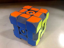
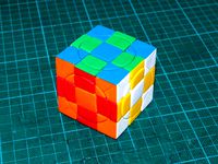
So… I’m a competitive speedcuber. I solve Rubik’s Cubes really fast. A big part of this hobby is hardware; you have to have cubes that can move as fast as you can turn it if you’re going to be very quick. Over time, there have been countless designs, the first being from Rubik’s, but most being from other manufacturers, such as Moyu, Qiyi, Yuxin, Dayan, and many more. The speedcubing marketplace is very interesting because of the number of companies designing better and better cubes to try and come out on top of all the others. New cubes are iterated very quickly, with a new 3x3 (the standard size of puzzle) coming out at least once a month. Most of these cubes use almost the exact same mechanism to achieve their smooth turning and cornercutting (the ability for the cube to cope with slightly misaligned layers), with just changing the profile of the puzzle a little (we’ll get to what that means later). This means that all the current cubes on the market, unfortunately, have some of the same problems.
One of the main problems that my design fixes is spring noise. In other cubes, every piece on the face of the cube turns with the move, including the centerpiece. Inside the center, there is a screw, threaded into the core, that has a spring sandwiched between the head of the screw and the bottom face of the centerpiece. This spring allow the centerpiece to move away from the core a little, but be pushed back, and is very important to the cornercutting of the cube. The problem is that the centers are square, to fit in the grid, and it has to turn with the face. This means that the spring has to rotate against at least one of the faces it is contacting (the bottom face of the centerpiece or the head of the screw). This motion makes a ping-ping-ping sound as you turn the face, and that becomes really annoying. This problem can be mostly mitigated by putting small washers on those surfaces, and by lubricating it, but it is hard to completely get rid of. So what’s the solution?
My circular-centerpiece design solves this problem simply by not having the centerpiece turn with the face. The centerpiece is just a rotated profile, which allows the face to turn around it. The core has some prongs on it to make sure the centerpiece and the core don’t rotate relative to each other, while still letting the center slide out a little. This design also keeps the pieces in the cube a bit better than other designs, which is a problem on some cubes. In the speedcubing community, this is called a pop, and it almost never happens with this design. I’m not really willing to say that this concept is fundamentally better than a rotating-centerpiece design, but I do think it has potential, and with the refinement that has been put into other cubes on the market, it could make a very good puzzle.
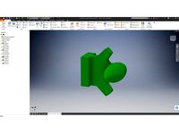
I designed this cube in Autodesk Inventor, admittedly about a year ago, and it was honestly before I was really adept with any CAD software. I was just learning the “right” way to do things, and you can clearly see that in the build tree if you open the .ipt or .iam files. Since then, I have done much more CAD, and gotten a lot more efficient with my workflow. The entire design process revolves around what I call the “profile” of the cube. This is a shape that is used in revolve features to make every part of the puzzle. I started by sketching the profile in my sketchbook, then transferred that into Inventor to start the CAD process. This was used to create a rotation with the surface of the edgepiece that contacts the centerpiece. Then, I used a revolve cut feature and cut the inverse of that profile into the other part of the edgepiece that would contact the cornerpiece. After that, I used that inverse of the profile again in a revolve to make the centerpiece. The cornerpiece used three of the original profiles, cut out with rotations again, the gain its shape. One of the most amazing things I found in this process is that all of the revolves are around the same three axes, that all the the faces turn around. It’s just such an elegant design process, and I’m sure that you could make it entirely parametric with a code-based CAD program like OpenSCAD, which is something I will probably try once I have the time to learn how. After all this, there are some adjustments made, like creating space for the hardware in the centerpieces, and making the core with the interlocking mechanism to the centerpiece.
After this, it was time to try and 3D print the design. At the time, I had a Monoprice Maker Select V2.1 (Wanhao Duplicator i3 rebrand), and no other working printers. I exported the files in .stl format from Inventor, then sliced then in Cura at 2x scale, so the printer could handle the detail better, and printed them in ESun ProPLA. It was probably about 100 hours just printing the one cube in several 12-or-so hour prints. Then, it was off to the local hardware store buy the 6 screws, springs, and washers that I needed to finally assemble it. So far, I haven’t been able to print the second version that I designed because my printer broke shortly afterwards, and I haven’t had it consistently printing since. So how’d it work?
The V1 prototype really didn’t come out that great. It turns, and cornercuts a little, but that’s about it. The profile I designed has some flaws, probably the biggest of which it that the cornerpieces’ main torpedoes (any part of a piece that goes under another piece in order to hold it in the cube) were designed to be free-floating from the actual cubie (individual piece -- corner, edge, or center -- with stickers on it). This allowed the rest of the profile to be more exaggerated, essentially cutting off the main torpedo from the rest of the cubie. I thought that the secondary torpedo on the corners would be enough to hold them in, and that the floating torpedoes inside the cube would ride smoothly in their channels; I was wrong. The floating torpedoes made the entire cube lock up badly when trying to turn, and I had to just take them out to get decent turning. As for the secondary torpedoes keeping the corners in, that didn’t work so well either; they sometimes pop while turning faster because of the lack of a real traditional torpedo. This is fixed in the CAD file for the V2, and shouldn’t be a problem when I get a working printer and print it.
As for professionally printing this, it would have some major benefits. This could be successfully printed using SLS, DLMS, Polyjet, or really high-end FDM technology. I think that Polyjet would be the best option for a few reasons. First, it has the level of detail necessary, and has dissolvable supports for the complex geometry. Furthermore, you could have the printer print color in the model, allowing for the stickers on the puzzle to be replaced with, simply, colored plastic. This is called a stickerless puzzle in the cubing community, but it is usually done with injection-molding individual “leafs,” so that a corner would be split into three leafs and an edge, two. These are assembled to give the cube its colors, but makes it a weaker puzzle. Polyjet would allow for a stronger cube, while still giving the puzzle a stickerless feel. This technology would allow for faster prototyping, albeit on a bit looser of a budget than mine. Cubing hardware is not a mechanical system that can be tested in software or just designed more properly to make it better. It takes trial and error, all with physical prototypes, to improve the design. This process would really not be possible if it wasn’t for 3D printing.
School: Newberg Senior High School
Instructor: Eric Carlson
This is a submission for Paul Sperling.
One of the main problems that my design fixes is spring noise. In other cubes, every piece on the face of the cube turns with the move, including the centerpiece. Inside the center, there is a screw, threaded into the core, that has a spring sandwiched between the head of the screw and the bottom face of the centerpiece. This spring allow the centerpiece to move away from the core a little, but be pushed back, and is very important to the cornercutting of the cube. The problem is that the centers are square, to fit in the grid, and it has to turn with the face. This means that the spring has to rotate against at least one of the faces it is contacting (the bottom face of the centerpiece or the head of the screw). This motion makes a ping-ping-ping sound as you turn the face, and that becomes really annoying. This problem can be mostly mitigated by putting small washers on those surfaces, and by lubricating it, but it is hard to completely get rid of. So what’s the solution?
My circular-centerpiece design solves this problem simply by not having the centerpiece turn with the face. The centerpiece is just a rotated profile, which allows the face to turn around it. The core has some prongs on it to make sure the centerpiece and the core don’t rotate relative to each other, while still letting the center slide out a little. This design also keeps the pieces in the cube a bit better than other designs, which is a problem on some cubes. In the speedcubing community, this is called a pop, and it almost never happens with this design. I’m not really willing to say that this concept is fundamentally better than a rotating-centerpiece design, but I do think it has potential, and with the refinement that has been put into other cubes on the market, it could make a very good puzzle.
I designed this cube in Autodesk Inventor, admittedly about a year ago, and it was honestly before I was really adept with any CAD software. I was just learning the “right” way to do things, and you can clearly see that in the build tree if you open the .ipt or .iam files. Since then, I have done much more CAD, and gotten a lot more efficient with my workflow. The entire design process revolves around what I call the “profile” of the cube. This is a shape that is used in revolve features to make every part of the puzzle. I started by sketching the profile in my sketchbook, then transferred that into Inventor to start the CAD process. This was used to create a rotation with the surface of the edgepiece that contacts the centerpiece. Then, I used a revolve cut feature and cut the inverse of that profile into the other part of the edgepiece that would contact the cornerpiece. After that, I used that inverse of the profile again in a revolve to make the centerpiece. The cornerpiece used three of the original profiles, cut out with rotations again, the gain its shape. One of the most amazing things I found in this process is that all of the revolves are around the same three axes, that all the the faces turn around. It’s just such an elegant design process, and I’m sure that you could make it entirely parametric with a code-based CAD program like OpenSCAD, which is something I will probably try once I have the time to learn how. After all this, there are some adjustments made, like creating space for the hardware in the centerpieces, and making the core with the interlocking mechanism to the centerpiece.
After this, it was time to try and 3D print the design. At the time, I had a Monoprice Maker Select V2.1 (Wanhao Duplicator i3 rebrand), and no other working printers. I exported the files in .stl format from Inventor, then sliced then in Cura at 2x scale, so the printer could handle the detail better, and printed them in ESun ProPLA. It was probably about 100 hours just printing the one cube in several 12-or-so hour prints. Then, it was off to the local hardware store buy the 6 screws, springs, and washers that I needed to finally assemble it. So far, I haven’t been able to print the second version that I designed because my printer broke shortly afterwards, and I haven’t had it consistently printing since. So how’d it work?
The V1 prototype really didn’t come out that great. It turns, and cornercuts a little, but that’s about it. The profile I designed has some flaws, probably the biggest of which it that the cornerpieces’ main torpedoes (any part of a piece that goes under another piece in order to hold it in the cube) were designed to be free-floating from the actual cubie (individual piece -- corner, edge, or center -- with stickers on it). This allowed the rest of the profile to be more exaggerated, essentially cutting off the main torpedo from the rest of the cubie. I thought that the secondary torpedo on the corners would be enough to hold them in, and that the floating torpedoes inside the cube would ride smoothly in their channels; I was wrong. The floating torpedoes made the entire cube lock up badly when trying to turn, and I had to just take them out to get decent turning. As for the secondary torpedoes keeping the corners in, that didn’t work so well either; they sometimes pop while turning faster because of the lack of a real traditional torpedo. This is fixed in the CAD file for the V2, and shouldn’t be a problem when I get a working printer and print it.
As for professionally printing this, it would have some major benefits. This could be successfully printed using SLS, DLMS, Polyjet, or really high-end FDM technology. I think that Polyjet would be the best option for a few reasons. First, it has the level of detail necessary, and has dissolvable supports for the complex geometry. Furthermore, you could have the printer print color in the model, allowing for the stickers on the puzzle to be replaced with, simply, colored plastic. This is called a stickerless puzzle in the cubing community, but it is usually done with injection-molding individual “leafs,” so that a corner would be split into three leafs and an edge, two. These are assembled to give the cube its colors, but makes it a weaker puzzle. Polyjet would allow for a stronger cube, while still giving the puzzle a stickerless feel. This technology would allow for faster prototyping, albeit on a bit looser of a budget than mine. Cubing hardware is not a mechanical system that can be tested in software or just designed more properly to make it better. It takes trial and error, all with physical prototypes, to improve the design. This process would really not be possible if it wasn’t for 3D printing.
School: Newberg Senior High School
Instructor: Eric Carlson
This is a submission for Paul Sperling.
Similar models
thingiverse
free
Helicopter 2x2 Twisty Puzzle v1 (Deprecated) by kequals
...core part 1
1 core part 2
this puzzle is screwless, so can be entirely 3d printed. stickers can be cut from the sticker template.
thingiverse
free

40mm Puzzle Cube by Dravakiirm
...wall thickness problems you shouldn't have too many problems with this print.
assembly guide and cheat sheet coming soon....
thingiverse
free
8-axis Cube Core (assembly) by grafalex
...ce in details at https://cad.onshape.com/documents/0c898146eff8a4ab038c2c37/v/965c9b87c16fa7cf4b113b59/e/a97d32a0ffa55f3f443a0366
grabcad
free

Da Vinci's Magic Cube (Updated)
... that are easier to turn and better spacing. it printed well and if printed without rafts would only require minor post cleanup.
thingiverse
free

Puzzle cube
... an old puzzle i had as a child.
if you have problem assembling parts, use sandpaper to better fit the parts.
cube size is 30 mm.
thingiverse
free
Interlocking Puzzle Cube 4x4 by RaoulDuke
...lems assembling your cube, download burrtools and increase the clearance between parts.
the puzzle needs seven moves to assemble.
thingiverse
free

Melting Cube Puzzle V2 by H4I2
...e.
it is a dove-tail puzzle that doesn't open as simply.
please post your printed photos as a make, i would love to see them.
thingiverse
free
Dayan Zhanchi torpedo by DJ_AJ
...n parts of the cube, the cube will physically work better. i lost one that was in my cube, so i designed this. hope you enjoy it!
thingiverse
free

RCP Copter Tower House Puzzle by rcpongo
...springs from that puzzle. this has been designed around those specific parts, so using them will result in the best final result.
thingiverse
free
Crazy 3x3x3 Plus cube (whole original series + 2face series) by grafalex
...pieces for classic crazy cube (faces are 0 or 1). use your favorite printing method. parts havr non-split prefix in the file name
Centerpiece
design_connected
$18

Pumpkin Centerpiece
...pumpkin centerpiece
designconnected
pumpkin centerpiece computer generated 3d model.
turbosquid
$100
Lotus Centerpiece
...
royalty free 3d model lotus centerpiece for download as 3dm on turbosquid: 3d models for games, architecture, videos. (1665018)
turbosquid
$4

garden centerpiece.
...royalty free 3d model garden centerpiece. for download as obj on turbosquid: 3d models for games, architecture, videos. (1348511)
design_connected
$25

Spring Pansy Centerpiece
...spring pansy centerpiece
designconnected
spring pansy centerpiece computer generated 3d model.
design_connected
$10

DOMINIQUE PIERRAT Centerpiece
...dominique pierrat centerpiece
designconnected
dominique pierrat centerpiece computer generated 3d model.
turbosquid
free

Candles centerpiece
... available on turbo squid, the world's leading provider of digital 3d models for visualization, films, television, and games.
design_connected
$27

Amaranthus & Nerine Centerpiece
...amaranthus & nerine centerpiece
designconnected
amaranthus & nerine centerpiece computer generated 3d model.
turbosquid
$32
Elegant Stairs & Centerpiece
...3d model elegant stairs & centerpiece for download as skp on turbosquid: 3d models for games, architecture, videos. (1305152)
turbosquid
$15

Halloween candle centerpiece
... available on turbo squid, the world's leading provider of digital 3d models for visualization, films, television, and games.
turbosquid
$12

Table Centerpiece Decoration
... available on turbo squid, the world's leading provider of digital 3d models for visualization, films, television, and games.
3X3
turbosquid
$45

Booth 3x3
...rbosquid
royalty free 3d model booth 3x3 for download as max on turbosquid: 3d models for games, architecture, videos. (1672140)
3d_export
$6

exhibition booth 3x3
...exhibition booth 3x3
3dexport
3d_ocean
$3
truss trio 3x3 meter
...truss trio 3x3 meter
3docean
3x3 meter trio truss
truss trio 3×3 meter
turbosquid
$6
Exhibition booth 3x3
...l exhibition booth 3x3 for download as 3ds, max, obj, and fbx on turbosquid: 3d models for games, architecture, videos. (1427993)
turbosquid
$3

exhibition stand 3x3 meters
...free 3d model exhibition stand 3x3 meters for download as max on turbosquid: 3d models for games, architecture, videos. (1703891)
turbosquid
$29

3D Exhibition Booth 3x3
... available on turbo squid, the world's leading provider of digital 3d models for visualization, films, television, and games.
turbosquid
$29

3D Exhibition Booth 3x3
... available on turbo squid, the world's leading provider of digital 3d models for visualization, films, television, and games.
3d_ocean
$5

Rubik Cube 3x3
...model detail. included files : .max (2010 & 2013) + vray version .fbx (multi format) .obj (multi format) .3ds (multi format)
turbosquid
free

Foto studio 1x1, 3x3, 5x5
...
free 3d model foto studio 1x1, 3x3, 5x5 for download as c4d on turbosquid: 3d models for games, architecture, videos. (1250313)
3d_export
$10
3x3 system octanorm Booth Design
...implemented with lumion the attached file is max for modification. with the same details as the real materials for implementation
Circular
3ddd
$1

Circular Library
...circular library
3ddd
библиотека , стеллаж
circular library
3d_export
$5
Horizontal circular saw
...horizontal circular saw
3dexport
horizontal circular saw
turbosquid
$10
Circular sword
...osquid
royalty free 3d model circular sword for download as on turbosquid: 3d models for games, architecture, videos. (1402076)
3ddd
$1
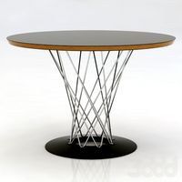
Noguchi circular table
...noguchi circular table
3ddd
круглый
noguchi circular table
turbosquid
$10
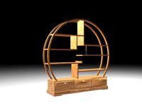
Circular Shelf
...alty free 3d model circular shelf for download as max and obj on turbosquid: 3d models for games, architecture, videos. (1315073)
turbosquid
$5
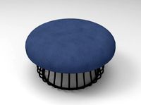
Circular Ottoman
...ty free 3d model circular ottoman for download as obj and fbx on turbosquid: 3d models for games, architecture, videos. (1414413)
3d_export
$10
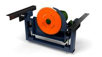
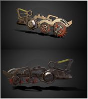
Circular machine
...circular machine
3dexport
turbosquid
$6
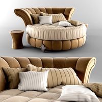
Circular Bed
... free 3d model circular bed for download as max, fbx, and prj on turbosquid: 3d models for games, architecture, videos. (1466410)
3ddd
$1
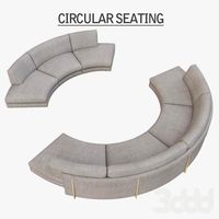
Circular Seating
...дульный
circular seating in 3dsmax 2010 & 2012 vray scene with maps & materials carefully unwrapped, obj format included.
3ddd
$1

knitted circular carpet
...knitted circular carpet
3ddd
ковер , круглый
knitted circular carpet
size:d-180sm