Thingiverse
Tevo Tarantula Single Motor Dual Z Axis by NinjaCookie
by Thingiverse
Last crawled date: 3 years ago
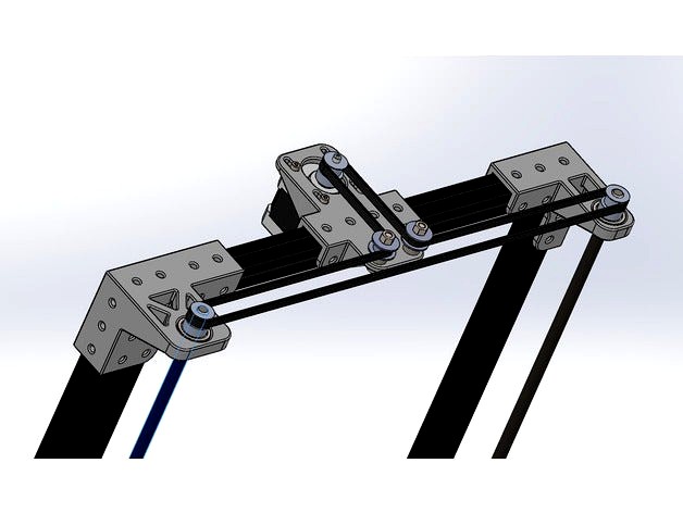
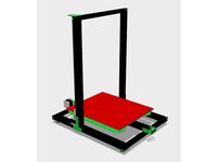
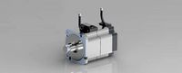
These parts are designed to give the Tevo Tarantula Dual Z axis from a single motor. I won't go into the pros and cons here, as it's complicated. No more motor couplers though, so makes things easier! It is a little more fiddly than dual motors, although requires no extra electronics.
They are remixed from the excellent brackets by thingirob. I have remodeled these parts completely so they do look slightly different.Please note I have added tolerances where the original parts had none, these should print fine without scaling.
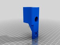
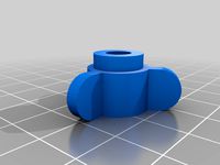
You need 2 of the Z Nut holders. I have included x2 in the name, but just to remind you.
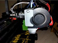
Please note the photo I have included is v1. I have updated the designs since then to improve them based on my experiences.
Additional Hardware
You will need the following parts to put it together. Many of the screws etc. were spares from the kit, or left over from other changes I have made for the printer.
900mm closed loop GT2 belt. I found a seller on AliExpress that made these very cheaply. Link may disappear if they stop selling them.
4 x 608 Bearings
2 x 400mm lead screws. Threads need to match. Also need standard brass nuts.
2 x 8mm bore 20 tooth pulley. Seller I used
5mm bore 20 tooth pulley for motor. Seller I used
2 x Smooth Idler Pulleys w/ 16mm diameter. I had these so no seller, although commonly available. Basically same pulley used on other axes of Tarantula.
2 x 25mm M5 Screws. Can be longer.
2 x Nylon spaces or nuts.
M5 washers (to use to space idlers correctly. I used 4).
2 x M5 nuts, ideally nylock nuts.
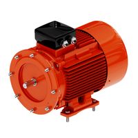
Nema 17 motor from original Z axis.
4 x M3 screws to mount Motor (should already have these with original brackets).
8 x M3 screws and nuts to mount brass nuts.
M4 T Nuts and screws. I won't include the amounts, however I would suggest using a minimum of 8 on each bracket, and 2 for each of the Nut holders. This would be 44 of each.
Optional 2 x 8mm lock collars. The screws are held in place by gravity, however you can add lock collars underneath the upper bearing bracket. I do not use them, as in the event that the print head crashes into bed, the screws lift out of the bearings and prevent damage.
Putting it together
Brackets and Lead Screws
Put together the printer with the brackets as normal. Take care to try to align the brackets as best as possible.
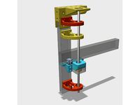
Insert bearings into relevant spaces in brackets. Should fit well, although may need some sanding depending on how well your printer is set up.
Add brass nut to Z nut holders. Use M3 screws and nuts to securely fasten.
Attach 8mm bore pulleys to end of lead screws and tighten grub screws well.
Insert Lead screws through upper bearings, then thread on Z nuts, finally push lead screws into bottom bearings. If using 400mm screws, none of the screw will come out the other side, this bearing just supports it at each end.
Secure z nut holders to X axis. Care should be taken here to measure the distance from each side to a fixed point on the frame (top or bottom, not the bed), to ensure it is square. Use the lead screws to adjust up and down manually. It is easiest to have the T nuts in the slots properly, but leave them loose while adjusting, and tighten only at the end.
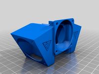
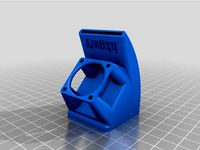
Motor Mount
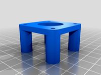
Attach stepper motor to motor mount. M3 screws should still be a little loose, letting the motor move along the slots.
Mount should then be attached to frame. Position as centrally as possible.
Add pulley to Motor and try to level with pulleys on lead screws. A straight edge like a ruler can be helpful here.
Push M5 screw through relevant hole for idler pulley. Add the nylon spacer (or nut if using instead), then add washers (2 for each). Finally put on the pulley and add final nylock nut. These also need to be checked for height against the other pulleys. You may need to add or remove washers to get the heights right.
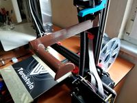
If the X axis is straight now, you can attach the belt. This should be threaded around the pulleys as show in the pictures. The last pulley can be a little tight due to limitations in the frame, but should go over without too much trouble.
Tension the belt by pulling the Motor back in it's slot then tightening the screws. Given how this works having really high tension is not as critical as it is on the other axes.
Manually rotate the motor pulley (with care!) to ensure the mechanism moves freely, and doesn't bind up.
Firmware changes
You need to invert the Z motor direction in the firmware for this to work correctly. That is the only change you need to make (unless you have changed thread pitch at all).
Important Notes
It has been pointed out to me that unless alignment is perfect, having the screws supported on both end will lead to binding. I don't have a problem with this myself, however if you do, the best thing is to simply pop out the bottom bearings and not use them.
As with any modification to a printer, make sure you test well, through the whole range of motion of the Z axis to ensure it moves freely and does not bind.
You may need to up the current to the Z motor slightly, as it is working a little harder than it was.
I needed to buy a longer Motor wire due to moving the Z axis. Depending how you mount your electronics, you may not need to do this.
Feedback
I greatly appreciate any feedback you have! If you have an problems, I am happy to help where I can.
Improvements from v1
Removed some material to improve strength.
Added ribs to upper brackets to improve strength.
Fixed an alignment issue with some holes.
Adjusted hole spacing under bearing blocks so all previous holes present.
Increased travel for motor to allow more belt tension if required.
They are remixed from the excellent brackets by thingirob. I have remodeled these parts completely so they do look slightly different.Please note I have added tolerances where the original parts had none, these should print fine without scaling.
You need 2 of the Z Nut holders. I have included x2 in the name, but just to remind you.
Please note the photo I have included is v1. I have updated the designs since then to improve them based on my experiences.
Additional Hardware
You will need the following parts to put it together. Many of the screws etc. were spares from the kit, or left over from other changes I have made for the printer.
900mm closed loop GT2 belt. I found a seller on AliExpress that made these very cheaply. Link may disappear if they stop selling them.
4 x 608 Bearings
2 x 400mm lead screws. Threads need to match. Also need standard brass nuts.
2 x 8mm bore 20 tooth pulley. Seller I used
5mm bore 20 tooth pulley for motor. Seller I used
2 x Smooth Idler Pulleys w/ 16mm diameter. I had these so no seller, although commonly available. Basically same pulley used on other axes of Tarantula.
2 x 25mm M5 Screws. Can be longer.
2 x Nylon spaces or nuts.
M5 washers (to use to space idlers correctly. I used 4).
2 x M5 nuts, ideally nylock nuts.
Nema 17 motor from original Z axis.
4 x M3 screws to mount Motor (should already have these with original brackets).
8 x M3 screws and nuts to mount brass nuts.
M4 T Nuts and screws. I won't include the amounts, however I would suggest using a minimum of 8 on each bracket, and 2 for each of the Nut holders. This would be 44 of each.
Optional 2 x 8mm lock collars. The screws are held in place by gravity, however you can add lock collars underneath the upper bearing bracket. I do not use them, as in the event that the print head crashes into bed, the screws lift out of the bearings and prevent damage.
Putting it together
Brackets and Lead Screws
Put together the printer with the brackets as normal. Take care to try to align the brackets as best as possible.
Insert bearings into relevant spaces in brackets. Should fit well, although may need some sanding depending on how well your printer is set up.
Add brass nut to Z nut holders. Use M3 screws and nuts to securely fasten.
Attach 8mm bore pulleys to end of lead screws and tighten grub screws well.
Insert Lead screws through upper bearings, then thread on Z nuts, finally push lead screws into bottom bearings. If using 400mm screws, none of the screw will come out the other side, this bearing just supports it at each end.
Secure z nut holders to X axis. Care should be taken here to measure the distance from each side to a fixed point on the frame (top or bottom, not the bed), to ensure it is square. Use the lead screws to adjust up and down manually. It is easiest to have the T nuts in the slots properly, but leave them loose while adjusting, and tighten only at the end.
Motor Mount
Attach stepper motor to motor mount. M3 screws should still be a little loose, letting the motor move along the slots.
Mount should then be attached to frame. Position as centrally as possible.
Add pulley to Motor and try to level with pulleys on lead screws. A straight edge like a ruler can be helpful here.
Push M5 screw through relevant hole for idler pulley. Add the nylon spacer (or nut if using instead), then add washers (2 for each). Finally put on the pulley and add final nylock nut. These also need to be checked for height against the other pulleys. You may need to add or remove washers to get the heights right.
If the X axis is straight now, you can attach the belt. This should be threaded around the pulleys as show in the pictures. The last pulley can be a little tight due to limitations in the frame, but should go over without too much trouble.
Tension the belt by pulling the Motor back in it's slot then tightening the screws. Given how this works having really high tension is not as critical as it is on the other axes.
Manually rotate the motor pulley (with care!) to ensure the mechanism moves freely, and doesn't bind up.
Firmware changes
You need to invert the Z motor direction in the firmware for this to work correctly. That is the only change you need to make (unless you have changed thread pitch at all).
Important Notes
It has been pointed out to me that unless alignment is perfect, having the screws supported on both end will lead to binding. I don't have a problem with this myself, however if you do, the best thing is to simply pop out the bottom bearings and not use them.
As with any modification to a printer, make sure you test well, through the whole range of motion of the Z axis to ensure it moves freely and does not bind.
You may need to up the current to the Z motor slightly, as it is working a little harder than it was.
I needed to buy a longer Motor wire due to moving the Z axis. Depending how you mount your electronics, you may not need to do this.
Feedback
I greatly appreciate any feedback you have! If you have an problems, I am happy to help where I can.
Improvements from v1
Removed some material to improve strength.
Added ribs to upper brackets to improve strength.
Fixed an alignment issue with some holes.
Adjusted hole spacing under bearing blocks so all previous holes present.
Increased travel for motor to allow more belt tension if required.
Similar models
thingiverse
free

BD's Tarantula X-Axis Motor and Idler Mounts by bdwalker1
... to adjust your z-carriages or drill new holes in the acrylic if the holes don't line up perfectly for your particular build.
thingiverse
free

TEVO Tarantula X & Y axis belts tensioners by alejandrosnz
...d the belt through the hole on the other piece. to mount the tensioner onto the y axis you have to ziptie it into the belt hole.
thingiverse
free

Tevo Tarantula Z axis belt drive by realadry
...e to adjust the design!!)
-) small zip ties
-) mounting materials: 10* m4 t-nuts and m4 8mm screws
please note instructions below
thingiverse
free

BD's Tarantula Z Motor and Nut Mounts by bdwalker1
... print bed. it moves things far enough back to allow the x-axis carriage to pass between the lead screw and the x-axis extrusion.
thingiverse
free

Tevo Tarantula Z-Axis MGN12 Rail Brackets/Mounts by evil_k
...
you will need to change the belt drive for the x-axis. the parts i used are on thingiverse. check the tevo tarantula collection.
thingiverse
free
Monoprice Select Mini dual z motor adapters by mfink70
... and needs.
update: 2/17/18
added a mount that will use 6mm linear bearings for those that have a 6mm rod for their z stabilizer.
thingiverse
free

Wanhao i3 Plus Y Axis Stiffening Brackets - Pulley and Stepper Motor Mounts by jinner
... any tensioners as the blets don't stretch over time and there are may reports of broken tensioners.
fusion 360 file included
thingiverse
free
Single Z-Axis Brackets for Tarantula by 3ff3ction
...g.
the lower part of the coupler is holding the z-axis on top of the bearing, and so almost all weight is hanging on the bracket.
thingiverse
free

Linear Rail / Tevo Tornado / Z Axis
...e lead screws
6x m5x45mm bolts and nuts for the linear rail mounts/rear z brackets (inner bolts will need to be cut down to size)
thingiverse
free

Tronxy X1 Z-Axis Gantry Bracket by simonwilson
... currently using can be found below!
250mm t8 8mm 'lead' lead screw
t8 backlash block link
3pcs - t8 backlash block link
Ninjacookie
thingiverse
free

NinjaCookie Bottomless lower brackets by 3DPModder
...ed the 4 holes that bolt into the horizontal extrusion by the same amount (4.5mm) so they would line up in the new configuration.
thingiverse
free

NinjaCookie Dual Z with pillowblock bearings by Xyruss
...-bearing-housing-kfl08-fl08-k08-flange-bearing-with/32363611626.html?spm=2114.search0104.8.9.1d5c4c0bpofk0t&pricebeautifyab=0
thingiverse
free

NinjaCookie's Dual Z Idler Support by JunkYardDawg
...re so i designed this bracket to sit atop of his inverted motor bracket and to hold the m5 bolts from below and above the idlers.
thingiverse
free

Tevo Tarantula Z-endstop mount for bracketed base by tdams09
...through the top hole on the base bracket of ninjacookie ...
thingiverse
free
motor mount by XennoNL
...by xennonl thingiverse this is an add on for ninjacookie#39;s https://www.thingiverse.com/thing:2014187 you can move the motor out of the...
thingiverse
free

Tevo Tarantula Single Motor Dual Z Axis Lower Right Bracket for Mechanical Endstop by eBoB_
...a quick and dirty remixed lower right bracket for ninjacookie#39;s single motor dual z. it has a mount for...
thingiverse
free

Tevo adjustable end stop by Xyruss
...endstop for the tevo to be compatible with the ninjacookie dual z brackets, as there was no option for...
thingiverse
free

Tevo Tarantula Single Motor Dual Z - original lead screw by reformy
...screw (which is shorter than the ones recommended by ninjacookie. i had a lot of problems with z wobble....
thingiverse
free

AM8 Single Motor Z Mod by Col_ChrisP
...the mean time just take a look at what ninjacookie has on his 'tevo tarantula single motor dual z'...
Tarantula
turbosquid
$5

tarantula
...rbosquid
royalty free 3d model tarantula for download as c4d on turbosquid: 3d models for games, architecture, videos. (1690032)
3d_ocean
$8

Tarantula
...rantula 3d model. perfect for animations or still image. textures psd and jpeg files included. modelled using autodesk maya 2011.
turbosquid
$50

tarantula
... available on turbo squid, the world's leading provider of digital 3d models for visualization, films, television, and games.
turbosquid
$45

Tarantula
... available on turbo squid, the world's leading provider of digital 3d models for visualization, films, television, and games.
turbosquid
$12

Spider black widow tarantula tarantula Insects
... black widow tarantula tarantula insects for download as max on turbosquid: 3d models for games, architecture, videos. (1582101)
3ddd
$1

Журнальный столик - tarantula
... бионика , tarantula
журнальный столик tarantula
h=600
d=2000
3d_export
$35

Tarantula
...: zbrush 3ds max ztool obj fbx dae 3ds stl properties : 20*20*8 production time : 23 hours 328 gram models are drawn with zbrush.
3d_ocean
$20

Tarantula spider
...igged, animated, uv textured. particle system for the fur. very easy to animate. a 250 frames animation is available in the pack.
turbosquid
$45

Tarantula Spider
... available on turbo squid, the world's leading provider of digital 3d models for visualization, films, television, and games.
3d_export
$5

spider tarantula
...spider tarantula
3dexport
3d model of a steppe spider for your ideas and projects.
Tevo
thingiverse
free

TEVO Logo by limwenyao
...verse
tevo logo - for customizing your builds to look cooler with the tevo logo! pdf version is editable with adobe illustrator.
thingiverse
free
Tevo Tornado e3d Tevo Flash Style fan Mount by DemolitionX
...an mount by demolitionx
thingiverse
just messing around and made a tevo flash style fan mount for the e3d v6 on the tevo tornado
thingiverse
free
BODEN TUBE CLAMP FOR TEVO TARANTULA PRO AND TEVO TORNADO
... and tevo tornado
thingiverse
bodwen tube clamp. printable adjustable tension clamp for tevo tarantula pro and tornado extruder.
thingiverse
free
TEVO Tornado Model by JMDesigns
...tevo tornado model by jmdesigns
thingiverse
tevo tornado model
thingiverse
free
Tevo Tarantula FanDuct by hkgary_g
...tevo tarantula fanduct by hkgary_g
thingiverse
fanduct for tevo tarantula
thingiverse
free
FAN TEVO TARANTULA by llprokall
...fan tevo tarantula by llprokall
thingiverse
fan tevo tarantula
thingiverse
free
Tevo Tarantula filament by Xbertus
...tevo tarantula filament by xbertus
thingiverse
suport for filamente tevo tarantula
thingiverse
free
TEVO Top Brackets by _Godoy_
...tevo top brackets by _godoy_
thingiverse
top brackets for tevo tarantula
thingiverse
free
Tevo Tarantula Spool Holder
...tevo tarantula spool holder
thingiverse
strong spool holder for tevo tarantula
thingiverse
free

tevo tarantula spacer by poundskinnyboy
...tevo tarantula spacer by poundskinnyboy
thingiverse
it's a tevo tarantula spacer
Dual
turbosquid
free

Dual Pistols
...ls
turbosquid
free 3d model dual pistols for download as fbx on turbosquid: 3d models for games, architecture, videos. (1320360)
turbosquid
$2
Dual Axe
...urbosquid
royalty free 3d model dual axe for download as fbx on turbosquid: 3d models for games, architecture, videos. (1332372)
turbosquid
$10
Dual Lesaths
... available on turbo squid, the world's leading provider of digital 3d models for visualization, films, television, and games.
3ddd
$1
плитка Dual Bianco (Испания)
...й плитки venis dual (испания). технические качества: устойчивость к стирания, отличная геометрия, отсутствие проблем при укладке.
turbosquid
$35

Dual Mesh Fonts
...ree 3d model dual mesh fonts for download as ma, obj, and fbx on turbosquid: 3d models for games, architecture, videos. (1352989)
turbosquid
$29

Dual Flask with Bungs
...del dual flask with bungs for download as obj, fbx, and blend on turbosquid: 3d models for games, architecture, videos. (1210512)
turbosquid
$19
Dual Socket Plug
...3d model dual socket plug for download as obj, fbx, and blend on turbosquid: 3d models for games, architecture, videos. (1303912)
turbosquid
$13
Dual Adjustable Pulley
... available on turbo squid, the world's leading provider of digital 3d models for visualization, films, television, and games.
turbosquid
$10

Amoi N809 Dual
... available on turbo squid, the world's leading provider of digital 3d models for visualization, films, television, and games.
turbosquid
$5
Dual Turret Tank
... available on turbo squid, the world's leading provider of digital 3d models for visualization, films, television, and games.
Axis
3ddd
$1

Мария Axis
...
3ddd
кухня , классическая , axis
модель кухни.
3d_export
$22
Axis robot 6-axis robotic arm
...ing parts drawings, standard parts purchased parts list, can be produced directly according to the drawings, welcome to download!
3ddd
free

Versatile Axis
...ddd
nexus , плитка
http://bvtileandstone.com/ceramic-porcelain/versatile-axis/
3d_export
$19
robot 2 axis
...robot 2 axis
3dexport
robot 2 axis
turbosquid
$40
Axis R5F
... available on turbo squid, the world's leading provider of digital 3d models for visualization, films, television, and games.
turbosquid
$40
Axis S5F
... available on turbo squid, the world's leading provider of digital 3d models for visualization, films, television, and games.
turbosquid
$30

Axis Athlon
... available on turbo squid, the world's leading provider of digital 3d models for visualization, films, television, and games.
turbosquid
$10

Linear Axis
... available on turbo squid, the world's leading provider of digital 3d models for visualization, films, television, and games.
3d_export
$15

drawing axis
...drawing axis
3dexport
simple rendering of the scene file
3ddd
$1

versatile axis ARC
...versatile axis arc
3ddd
versatile , плитка
versatile axis arc red dot design award
Z
3d_export
$5
nissan z
...nissan z
3dexport
nissan z
3ddd
$1

Vase Z
...vase z
3ddd
vase z
3ddd
$1
полотенцесушить Z
...полотенцесушить z
3ddd
полотенцесушитель
полотенцесушить z
design_connected
free

Z-Chair
...z-chair
designconnected
free 3d model of z-chair designed by karman, aleksei.
design_connected
$11
Z Lamp
...z lamp
designconnected
phillips z lamp computer generated 3d model. designed by kalff, louis.
3d_export
$5
Dragon balls z
...dragon balls z
3dexport
dragon ball z
turbosquid
$20

Fighter Z
...
turbosquid
royalty free 3d model fighter z for download as on turbosquid: 3d models for games, architecture, videos. (1292563)
turbosquid
$9

Pen Z
...pen z
turbosquid
free 3d model pen z for download as obj on turbosquid: 3d models for games, architecture, videos. (1686775)
turbosquid
free
z chair
...z chair
turbosquid
free 3d model z chair for download as max on turbosquid: 3d models for games, architecture, videos. (1410230)
turbosquid
$5

Letter Z
...urbosquid
royalty free 3d model letter z for download as max on turbosquid: 3d models for games, architecture, videos. (1408540)
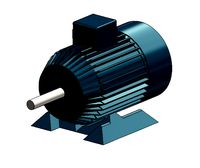
Motor
archibase_planet
free
Motor
...base planet
motor motor engine engine electric motor
motor wagner n250213 - 3d model (*.gsm+*.3ds) for interior 3d visualization.
archibase_planet
free
Motor
...motor
archibase planet
motor motor engine engine
motor n151112 - 3d model (*.gsm+*.3ds) for interior 3d visualization.
archibase_planet
free
Motor
...motor
archibase planet
motor motor engine engine
motor n150615 - 3d model (*.gsm+*.3ds+*.max) for interior 3d visualization.
turbosquid
$15
Motor
...otor
turbosquid
royalty free 3d model motor for download as on turbosquid: 3d models for games, architecture, videos. (1639404)
3d_ocean
$5
Electric motor
...electric motor
3docean
car electric engine industry motor phase train vehicle
an electric motor enjoy!
3d_ocean
$18
Electric Motor
...electric motor
3docean
electric motor engine machine mover parts
3d model electric motor for hoist crane
turbosquid
$29
Motor
... available on turbo squid, the world's leading provider of digital 3d models for visualization, films, television, and games.
turbosquid
$5
Motor
... available on turbo squid, the world's leading provider of digital 3d models for visualization, films, television, and games.
3d_export
$5
electric motor
...electric motor
3dexport
electric motor use for industrial purposes
3d_export
$5
servo motor
...tor
3dexport
it's a simple part of servo motor 0.75kw for used in machines assembly to show specified motor in own project.
Single
3d_export
$5

single sofa single chair
...single sofa single chair
3dexport
single sofa single chair 3d model
3d_export
$5

single sofa single chair
...single sofa single chair
3dexport
single sofa single chair 3d model
3d_export
$5

single fastener
...single fastener
3dexport
single fastener
3ddd
$1
Single FLOU
... sofa , трансформер
диван-трансформер single от итальянского производителя flou
3ddd
$1

bed single
...bed single
3ddd
постельное белье
bed single 190cm*90cm
3ddd
$1

Single Flou
...single flou
3ddd
качественная моделька дивана-трансформера single flou.
3d_ocean
$9
Single sofa
...le sofa
3docean
modern sofa single sofa sofa white sofa.comfortable sofa
single sofa,sofa,modern sofa,white sofa.comfortable sofa
3d_export
free

Single Knife
...single knife
3dexport
a single knife, presumably it was used as one of the throwing knives.
3d_export
free

couch - single
...couch - single
3dexport
low poly single couch with .psd file for personal customization
3d_ocean
$5
Single Sofa
...single sofa
3docean
single sofa made by fabric , wood frame & ss leg