Thingiverse
Telsa Phone Charger NO SUPPORTS REQ'D by swholmstead
by Thingiverse
Last crawled date: 3 years ago
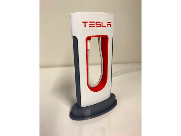
I love the design from https://www.mysupercharger.net/ for this Tesla Supercharger phone charger. However, it appears that it was made in Blender, requires crazy supports, and is very difficult to print.
I wanted a model that is EASY to print and requires NO SUPPORTS. This model was created from scratch in Fusion 360. All the pieces are printed laying down. All pieces are designed for a tight fit (0.25 mm tolerance), so no glue is required. The red lettering is designed to be pressed into white side pieces. I used a hammer to gently "motivate" the letters into place.
UPDATE 8/25/2017
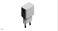
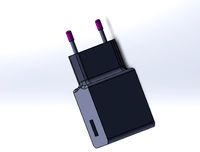
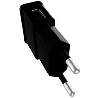
All of the base parts are for lightning connectors (6.7 mm x 1.5 mm) and have openings for connector heads of 7 mm x 10 mm and 3.0 mm cable diameter.
USB-C connectors (8.3 mm x 2.5 mm) use all of the base parts except where there is a USB-C version. These allows openings for connector heads of 8 mm x 11 mm and 3.5 mm cable diameter.
micro-USB connectors (6.83 mm x 1.78 mm) use all of the base parts except where there is a micro-USB version. These allows openings for connector heads of 8 mm x 11 mm and 3.5 mm cable diameter.
UPDATE 11/18/2019
I exported a new version of the iPhone red center piece that should now be completed flat on the one side to make printing easier.
I created a version 2 of the red Tesla letters that are 0.1mm thinner than the original version to help those who are not able to get the letters to fit.
NOTE: Please let me know if you have a different charger that doesn't work with one of these and I can add a custom Red Center piece that works for you.
ASSEMBLY INSTRUCTIONS:
Insert the red center piece into the white side piece with the cord channel
Push the cord through the hole in the gray base
Push the cord through the hold in the red center
Adjust the length of exposed cord in the middle and then push the cord into the channel in the white side piece
Cover with the other white side piece
Push the 2 gray columns into the gray base
Slide the gray base assembly up into the top assembly
Push the cord out the side channel on the bottom and cover with the final gray base piece
I wanted a model that is EASY to print and requires NO SUPPORTS. This model was created from scratch in Fusion 360. All the pieces are printed laying down. All pieces are designed for a tight fit (0.25 mm tolerance), so no glue is required. The red lettering is designed to be pressed into white side pieces. I used a hammer to gently "motivate" the letters into place.
UPDATE 8/25/2017
All of the base parts are for lightning connectors (6.7 mm x 1.5 mm) and have openings for connector heads of 7 mm x 10 mm and 3.0 mm cable diameter.
USB-C connectors (8.3 mm x 2.5 mm) use all of the base parts except where there is a USB-C version. These allows openings for connector heads of 8 mm x 11 mm and 3.5 mm cable diameter.
micro-USB connectors (6.83 mm x 1.78 mm) use all of the base parts except where there is a micro-USB version. These allows openings for connector heads of 8 mm x 11 mm and 3.5 mm cable diameter.
UPDATE 11/18/2019
I exported a new version of the iPhone red center piece that should now be completed flat on the one side to make printing easier.
I created a version 2 of the red Tesla letters that are 0.1mm thinner than the original version to help those who are not able to get the letters to fit.
NOTE: Please let me know if you have a different charger that doesn't work with one of these and I can add a custom Red Center piece that works for you.
ASSEMBLY INSTRUCTIONS:
Insert the red center piece into the white side piece with the cord channel
Push the cord through the hole in the gray base
Push the cord through the hold in the red center
Adjust the length of exposed cord in the middle and then push the cord into the channel in the white side piece
Cover with the other white side piece
Push the 2 gray columns into the gray base
Slide the gray base assembly up into the top assembly
Push the cord out the side channel on the bottom and cover with the final gray base piece
Similar models
thingiverse
free

tesla micro usb supercharger for note4 and note7 phones, with lighted sign by piratetv
... it fits a round lg qi charger and the charging cradle fits a note 4 sized phone. i use the cable for my camera or my work phone.
grabcad
free

USB Connector
...usb connector
grabcad
usb cord for phone charger. usb to micro usb connector
thingiverse
free

USB Cable Organizer | Cable Wrap by irvshapiro
...arge and the device connector is small. so i headed over to tinkercad and designed this simple and very easy to print organizer.
thingiverse
free

Fixed USB-C Center for the USB Tesla Charger by Raider1284
...ified in any way for your specific usb-c cables let me know and i can probably make the needed changes.
happy printing everyone!
3dwarehouse
free

usb to micro usb cable
...usb to micro usb cable
3dwarehouse
usb to micro usb cable #cable #connector #cord #micro #plug #usb #wire
thingiverse
free

Tesla charger holder (clamp/clip) by rkr007
...rse
this is another cable organizer for a tesla mobile connector. can clamp onto a piece of steel/angle iron. pictures to follow
cg_trader
$8

USB Charger with Apple Cord
...www.youtube.com/channel/ucqswwbo_r71wevci0jm2h_a wire cord cable power technology connector electricity architectural engineering
thingiverse
free

Tesla SuperCharger Phone Charger - Stand for big USB connectors
...ngiverse
i have manipulated the stand to support bigger usb connectors to be moved through the stand. now fits for 16x8mm plugs.
thingiverse
free

Cable / Cord organizer by rog0978
...erse
i was tired of the messy cables (chargers, usb cables etc.) so i came up with this simple but well working cable organizer.
3dwarehouse
free

Tesla Home charger cord holder
...tesla home charger cord holder
3dwarehouse
tesla charger holder #charger #tesla #tesla_model_s_charger
Telsa
3d_export
$200

Fallout Telsa Power Suit 3D Model
...allout telsa power suit 3d model
3dexport
fallout video game suit telsa
fallout telsa power suit 3d model scifipro 38924 3dexport
thingiverse
free

Telsa Cyberboat
...size to at least 150%. any critiques or suggestions to improve my models are most welcome. my 6 year old and i are just learning.
thingiverse
free

Telsa Samsung 8 Plus phone case by trujdmcngjfkd
...telsa samsung 8 plus phone case by trujdmcngjfkd
thingiverse
samsung 8 plus cell phone case featuring the tesla logo
thingiverse
free

Telsa Model S J1772 holder by RicksGadgets
... seat track. the holder can be positioned off the side or front. note, this will not work if the seat is in the forward position.
thingiverse
free

caliper mount holder designd by Telsa Israel staff by Isalvador
...et your awesome tesla-filament here:https://www.tesla-filament.com
our youtube channel link:https://www.youtube.com/teslafilament
thingiverse
free

TELSA | Cybertruck | Lighted Stand
...you 3d printed cybertruck :)
you need to print the 3d cybertruck first
3d cybertruck | https://www.thingiverse.com/thing:4010290
thingiverse
free

Trunk Storage Handle for Telsa Model 3 by Jaypirnts
...port needed, easy print.
just make sure temparature of the filament high enough for layer stability.
https://youtu.be/-nzygn4u9me
thingiverse
free

Slayer Exciter - Telsa Coil 1.2Kv
...lpful: https://youtu.be/zewh_op2cnk
some specs:
primary coil: 3.5 turns
secondary coil: 12 turns
output: 12000v 4ma
weight: 150gr
thingiverse
free

Tesla Cybertruck Mouse (Cybermouse)
...thingiverse this is a mouse case molded after the telsa ...
thingiverse
free

idler wheel for vacuum cleaner by 3DFethiye
...spare part for vacuum cleaner. it's working. model: arnica telsa ...
Swholmstead
thingiverse
free

Lords of Waterdeep meeples by swholmstead
... bought many years ago. i separated them into individual files and scaled them to match the size of the wooden ones that i have.
thingiverse
free

Kingdom Builder Crossroads Tokens by swholmstead
...ingdom builder. you need one of the ship and wagon and 2 soldiers. see http://www.thingiverse.com/thing:344381 for base tokens.
thingiverse
free

10 Minute Heist Player stand by swholmstead
...cardboard stands that fall off and don't store well. i decided to make a model for stands that stay on and work much better.
thingiverse
free

Patchwork Button Tokens by swholmstead
... for me, so i designed these.
you need to print 30 of the 1 button token, 12 of the 5 button token, and 6 of the 10 button token.
thingiverse
free

Filament Dust Cap by swholmstead
...cap. this allows the extruder motor to hold the dust cap tightly in place.
i included the .stp file if you want to make changes.
thingiverse
free

Laser Engraver and Warning Sign by swholmstead
...d a door hanger to warn family members that the laser is in use so they don't walk in unless they are wearing safety glasses.
thingiverse
free

Lowrider CNC End Caps by swholmstead
...- i added a y-axis homing switch to my cnc so i created a modified right end cap that has a screw to adjust y-axis home position.
thingiverse
free

Vast Crystal Caverns Event Marker by swholmstead
...ou need to print 10 of each stl to replace the cardboard bits from the game. use a drop of superglue to hold the parts together.
thingiverse
free

Baofeng UV-82 Charger by swholmstead
...r adjustments to the model to allow access to all keys on radio while sitting in charger.
timelapse: https://youtu.be/fjtsf5xxghg
thingiverse
free

Bicycle High Jump by swholmstead
...ily be adjusted by moving the holders to whatever height you would like.
https://youtu.be/ctdodp65yhohttps://youtu.be/46zjqau3eso
Req
thingiverse
free

blitzu mount v3 w/o GoPro (req) by mmaner
...blitzu mount v3 w/o gopro (req) by mmaner
thingiverse
blitzu mount v3 w/o gopro (req)
thingiverse
free

Tool holder for Makergear M2 (no hardware req.) by HeyZeus
... tool locations are labeled. alternate file with no text also provided
gcode provided is intended for use on a stock makergear m2
thingiverse
free

Festool TS 55 REQ Dust Cover by laanguiano
...dn't fit my ts55. i designed this model to be oversize. you have to file/sand this or it wont fit.
i printed at 100% infill
thingiverse
free

Strap adjuster for 30mm straps (no sewing req.) by Hasi0
... sewing requeried, just hammer in a 3mm steel rod, like in the picture. if it doesn't fit, just drill through with a 3mm bit.
thingiverse
free

Snapmaker 2 spool holder (req. 2x 608 bearings) by Twerqui
...or recycled from fidget spinners.
uploaded stl is a slight improvement on the pictured item.
freecad design available on request.
thingiverse
free

DeLorian key chain by fatbear666
...delorian key chain by fatbear666 thingiverse no req ...
thingiverse
free

Twisted Castle Vase by cidbaxter
...castle vase by cidbaxter thingiverse easy print no supports req ...
thingiverse
free
![[Req] General Lee - Dukes of Hazzard L*** compatible](/t/4910383.jpg)
[Req] General Lee - Dukes of Hazzard L*** compatible
....
twitch.tv/ionnight
i stream things i make.
0.2, 50% cubic infill, 3 walls. first time printing silver. it turned out very nice.
thingiverse
free

Side Swiper (cootie) Morse key. Minimal hardware req. by loughkb
...s for a cleaner looking result. the printed pla leaf springs work very well for returning to center. operation is quite smooth.
thingiverse
free

Nerf Vulcan shell links (cartridge-style.) HARDWARE REQ.
...t's mostly flair. this is a rigid system, so if you make it too long it may snap, but it will look great in brass coloration!
Charger
3d_export
$5
charger
...ers in battle. this is the 18th century meaning of charger, and it’s based on the verb charge and its meaning “rush into battle.”
3d_export
free
Charger
...charger
3dexport
turbosquid
$15

Charger
... available on turbo squid, the world's leading provider of digital 3d models for visualization, films, television, and games.
turbosquid
$3

Charger
...d model charger for download as skp, max, blend, stl, and obj on turbosquid: 3d models for games, architecture, videos. (1654816)
turbosquid
$1
charger
... available on turbo squid, the world's leading provider of digital 3d models for visualization, films, television, and games.
3d_export
$20

dodge charger 1972
...dodge charger 1972
3dexport
dodge charger 1972
3d_export
$20
dodge charger 1969
...dodge charger 1969
3dexport
dodge charger 1969
3d_export
free

dodge charger 1969
...dodge charger 1969
3dexport
dodge charger 1969
3d_export
$18

dodge charger
...dodge charger
3dexport
3d_export
$89
Charger 3D Model
...charger 3d model
3dexport
charger sea transopt industry 3d models
charger 3d model vitaly amurskiy 2286 3dexport
Phone
archibase_planet
free

Phone
...se planet
mobile phone smartphone cellular phone cell phone
phone n270513 - 3d model (*.gsm+*.3ds) for interior 3d visualization.
archibase_planet
free

Phone
... phone cell phone smartphone iphone cellular phone
phone iphone 4 apple n010113 - 3d model (*.3ds) for interior 3d visualization.
archibase_planet
free

Phone
...se planet
phone telephone dial telephone rotary phone
phone retro n130913 - 3d model (*.gsm+*.3ds) for interior 3d visualization.
archibase_planet
free

Phone
...se planet
phone telephone dial telephone rotary phone
phone n191213 - 3d model (*.gsm+*.3ds+*.max) for interior 3d visualization.
archibase_planet
free

Phone
...se planet
phone telephone rotary phone dial telephone
phone n150214 - 3d model (*.gsm+*.3ds+*.max) for interior 3d visualization.
archibase_planet
free

Phone
...se planet
phone telephone dial telephone rotary phone
phone n100414 - 3d model (*.gsm+*.3ds+*.max) for interior 3d visualization.
archibase_planet
free

Phone
...base planet
phone telephone rotary phone dial telephone
phone old n310116 - 3d model (*.gsm+*.3ds) for interior 3d visualization.
archibase_planet
free

Phone
...phone
archibase planet
equipment phone
phone n240110 - 3d model (*.3ds) for interior 3d visualization.
archibase_planet
free

Phone
...phone
archibase planet
telephone phone
mobile phone - 3d model (*.3ds) for interior 3d visualization.
archibase_planet
free

Phone
...phone
archibase planet
telephone phone
phone n021009 - 3d model (*.gsm+*.3ds) for interior 3d visualization.
Supports
turbosquid
$5

Support
... available on turbo squid, the world's leading provider of digital 3d models for visualization, films, television, and games.
3d_export
$8

Support 3D Model
...support 3d model
3dexport
support cantilever console
support 3d model tasal 73900 3dexport
3d_export
$5

phone support
...phone support
3dexport
phone
turbosquid
$12

Support bars
...squid
royalty free 3d model support bars for download as max on turbosquid: 3d models for games, architecture, videos. (1411542)
turbosquid
$8

support weights
...id
royalty free 3d model support weights for download as max on turbosquid: 3d models for games, architecture, videos. (1411538)
turbosquid
$2

headphone support
...royalty free 3d model headphone support for download as sldpr on turbosquid: 3d models for games, architecture, videos. (1357583)
turbosquid
$2

Support for flowers
...royalty free 3d model support for flowers for download as max on turbosquid: 3d models for games, architecture, videos. (1463543)
turbosquid
$14

Flower Support
...alty free 3d model flower support for download as max and obj on turbosquid: 3d models for games, architecture, videos. (1497066)
turbosquid
$5

serum support
...yalty free 3d model serum support for download as c4d and obj on turbosquid: 3d models for games, architecture, videos. (1551267)
3d_export
$10

spyro joystick support
...spyro joystick support
3dexport
joystick support of spyro dragon