Thingiverse
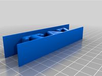
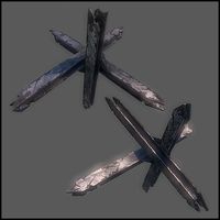
Taz 6 Anti Wobble by piercet
by Thingiverse
Last crawled date: 3 years ago
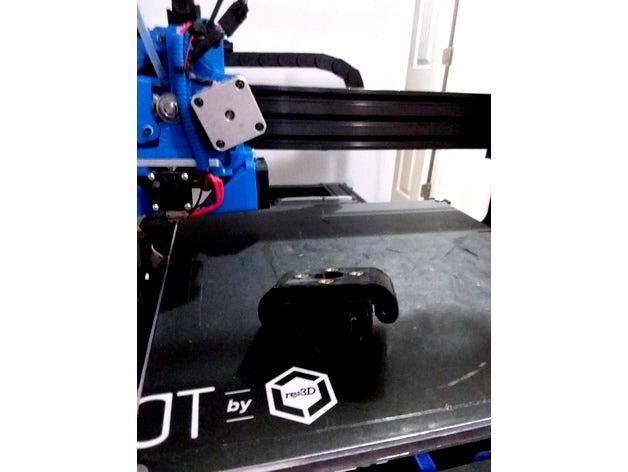
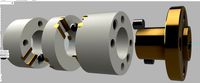
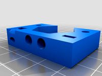
This is a Taz 6 specific variant of my existing Taz 5 Antiwobble design (https://www.thingiverse.com/thing:1089626) It uses the same steel pin and igus bearing design, just doubled up and eliminating the upper plate pins. it seems to work fine so far. This is the retrofit variant. A taz 6 x axis openbuilds specific variant built into the taz 6 openbuilds x motor and idler is also on the way.
Development thread here:https://forum.lulzbot.com/viewtopic.php?f=16&t=6820&p=37920#p37920
You will need the following parts:
8 M5 heat set inserts http://www.mcmaster.com/#94180a361/=zhts4o
4 3/16" 1 and 3/4" long steel shafts (locally sourced from Ace Hardware)
4 3/16" 2" long steel shafts (locally sourced from Ace Hardware)
16 Igus 2MTRI MYI-03-03 Flanged Bearing, 3/16" IDx 3/16" L (ebay)
the stock M5 bolts
4 additional m5 bolts (probably 10mm long?)
Instructions:
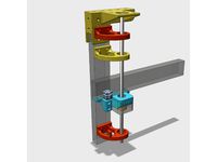
insert the M5 heat set nuts into the 4 holes in the upper mount.
insert the Igus bearings in the grooves. you will likely need to clearance the holes for good fit.
Bolt the lower piece onto the stock leadscrew mounring point in place of the leadscrew nut. Remove the green ring at that time.
Push the pins into place to lock the middle section over the lower section, I find its easiest to drill out one side and partially into another to make one side of the pin insertion point a friction fit.
Now install the upper section.
Bolt the leadscrew nut to the new wobble mount.
Notes:
1 This is experemental and untested. I don't have a taz 6 frame to fit it to. It should fit, but it may not. If it does fit, someone please let me know.
you will lose 10mm of theoretical total Z axis travel to fit this. it won't affect auto leveling or require any firmware modifications, but it does take up space in the upper section of the leadscrew.
This will likely fit any 10mm leadscrew that uses a 4 bolt mount pattern without too much modification. it won't fit a taz 5 easily due to the space claim required, but you may very well be able to use this with other printers.
Installation instructions:
Taz 6 Anti wobble assembly instructions 1.0a 11/29/2017
Move the Z axis to the middle of the printer area and power off the printer.
Remove the Z maximum limit switch mounting bolts.
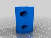
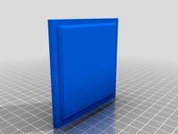
Insert the Z maximum limit switch height extender and mount with the stock M2 bolts. Use two additional M2 bolts to secure the limit switch in its new extended position. This will give the leadscrew nut the necessary clearance after inserting the anti wobbles.
Carefully Remove the Z axis top plate on the X motor leadscrew side.
Carefully release the coupler from the leadscrew or motor side of the Z motor / leadscrew interface. If it has been secured with Loctite skip this step.
Unbolt the leadscrew nut on the z Motor mount side and carefully remove the leadscrew. Also remove the Green flex washer. If the leadscrew coupler could not be removed, you may need to manually unthread the leadscrew nut by spinning it up and away from the mount. This is less desirable because you will have to reposition it later.
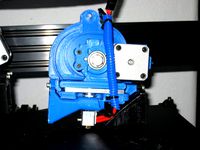
Bolt the lower wobble nut piece to the Z X motor mount.
Slide the middle anti wobble pins in place. It should require a bit of force to get them seated into the far holes. Once seated the middle wobble piece should slide back and forth smoothly and move at least 1mm.
Now place the top wobble piece in position and slide its pins into place. It should also move back and forth easily and move at least 1mm in the opposite axis. The entire anti wobble assembly should have no flex up or down in the Z axis, but should be able to move freely in X and Y.
Reinsert and Bolt the leadscrew nut back to the top anti wobble mount with 2-4 M5 bolts. You may omit 2 bolts if weight is a concern here.
If you were able to remove the coupler, now re-attach it and ensure the setscrews are tight. If you were unable to remove the coupler, you may have to re-thread the leadscrew bolt at this point down to the approximate location it was before. In that case you will need to use calipers to ensure that the leadscrew nuts on both sides of the assembly are the same height when finished.
Now repeat steps 4-11 on the Z X idler side of the printer. Doing one side at a time will minimize the possibility for significant frame position error.
When both sides are re-attached, use a set of calipers to ensure that the distance from the top of the leadscrew nut to the bottom of the upper leadscrew bearing bottom surface is the same on both sides of the printer.
Reattach power to the printer and turn it back on. It should be able to move the z axis up and down easily with no binding. Ensure you can safely travel the entire Z axis range with no binding slowly and carefully before proceeding with a test print.
Proceed with a test print. You should now see much less visible Z offset. If you encounter any layer separation or odd layer squish patterns that were not there before, ensure that the anti-wobble is not allowing any movement in the Z axis direction and adjust accordingly to make sure the pins cannot move up or down.
Development thread here:https://forum.lulzbot.com/viewtopic.php?f=16&t=6820&p=37920#p37920
You will need the following parts:
8 M5 heat set inserts http://www.mcmaster.com/#94180a361/=zhts4o
4 3/16" 1 and 3/4" long steel shafts (locally sourced from Ace Hardware)
4 3/16" 2" long steel shafts (locally sourced from Ace Hardware)
16 Igus 2MTRI MYI-03-03 Flanged Bearing, 3/16" IDx 3/16" L (ebay)
the stock M5 bolts
4 additional m5 bolts (probably 10mm long?)
Instructions:
insert the M5 heat set nuts into the 4 holes in the upper mount.
insert the Igus bearings in the grooves. you will likely need to clearance the holes for good fit.
Bolt the lower piece onto the stock leadscrew mounring point in place of the leadscrew nut. Remove the green ring at that time.
Push the pins into place to lock the middle section over the lower section, I find its easiest to drill out one side and partially into another to make one side of the pin insertion point a friction fit.
Now install the upper section.
Bolt the leadscrew nut to the new wobble mount.
Notes:
1 This is experemental and untested. I don't have a taz 6 frame to fit it to. It should fit, but it may not. If it does fit, someone please let me know.
you will lose 10mm of theoretical total Z axis travel to fit this. it won't affect auto leveling or require any firmware modifications, but it does take up space in the upper section of the leadscrew.
This will likely fit any 10mm leadscrew that uses a 4 bolt mount pattern without too much modification. it won't fit a taz 5 easily due to the space claim required, but you may very well be able to use this with other printers.
Installation instructions:
Taz 6 Anti wobble assembly instructions 1.0a 11/29/2017
Move the Z axis to the middle of the printer area and power off the printer.
Remove the Z maximum limit switch mounting bolts.
Insert the Z maximum limit switch height extender and mount with the stock M2 bolts. Use two additional M2 bolts to secure the limit switch in its new extended position. This will give the leadscrew nut the necessary clearance after inserting the anti wobbles.
Carefully Remove the Z axis top plate on the X motor leadscrew side.
Carefully release the coupler from the leadscrew or motor side of the Z motor / leadscrew interface. If it has been secured with Loctite skip this step.
Unbolt the leadscrew nut on the z Motor mount side and carefully remove the leadscrew. Also remove the Green flex washer. If the leadscrew coupler could not be removed, you may need to manually unthread the leadscrew nut by spinning it up and away from the mount. This is less desirable because you will have to reposition it later.
Bolt the lower wobble nut piece to the Z X motor mount.
Slide the middle anti wobble pins in place. It should require a bit of force to get them seated into the far holes. Once seated the middle wobble piece should slide back and forth smoothly and move at least 1mm.
Now place the top wobble piece in position and slide its pins into place. It should also move back and forth easily and move at least 1mm in the opposite axis. The entire anti wobble assembly should have no flex up or down in the Z axis, but should be able to move freely in X and Y.
Reinsert and Bolt the leadscrew nut back to the top anti wobble mount with 2-4 M5 bolts. You may omit 2 bolts if weight is a concern here.
If you were able to remove the coupler, now re-attach it and ensure the setscrews are tight. If you were unable to remove the coupler, you may have to re-thread the leadscrew bolt at this point down to the approximate location it was before. In that case you will need to use calipers to ensure that the leadscrew nuts on both sides of the assembly are the same height when finished.
Now repeat steps 4-11 on the Z X idler side of the printer. Doing one side at a time will minimize the possibility for significant frame position error.
When both sides are re-attached, use a set of calipers to ensure that the distance from the top of the leadscrew nut to the bottom of the upper leadscrew bearing bottom surface is the same on both sides of the printer.
Reattach power to the printer and turn it back on. It should be able to move the z axis up and down easily with no binding. Ensure you can safely travel the entire Z axis range with no binding slowly and carefully before proceeding with a test print.
Proceed with a test print. You should now see much less visible Z offset. If you encounter any layer separation or odd layer squish patterns that were not there before, ensure that the anti-wobble is not allowing any movement in the Z axis direction and adjust accordingly to make sure the pins cannot move up or down.
Similar models
thingiverse
free
K8200 z anti z-axis wobble
...ts and 3 regular nuts.
requires a linear bearing to work.
all holes are slightly oversized to compensate for printer inaccuracies
thingiverse
free
Single Z-Axis Brackets for Tarantula by 3ff3ction
...g.
the lower part of the coupler is holding the z-axis on top of the bearing, and so almost all weight is hanging on the bracket.
thingiverse
free
Ender 3 (V2) Z motor lead screw coupler and Z motor mount by MrWraith2
...upper bolts are way too long).
i printed the coupler vertically with no supports, and the z motor mount vertically with supports.
thingiverse
free
TR8 Anti Z-Wobble Rings by MakersMic
...sk.
materials list:
(16) 2mm x 5mm brass rod
(4) 3mm x 3mm neodynium magnets
(4) 3mm steel balls
(1) of each 3d printed component
thingiverse
free
Flexible coupling for Anycubic i3 mega z-axis by tierradenadie
... the z-axis.
the coupler has a side with a 8 mm bore and a 5 mm bore. i think, it might also be useful for other printer models.
thingiverse
free

Openbuilds v-slot X axis for Lulzbot TAZ 6 printers With integrated Z anti Wobble by piercet
...on picture is provided courtesy kam vedbrat and is used with permission, all rights for the photo remain with him. thank you kam!
thingiverse
free
HyperCube Z Nut Mounts various brass nuts by Tech2C
...epper motor
z_nut_mount_b for this integrated lead-screw stepper motor
z_nut_mount_c for this integrated lead-screw stepper motor
thingiverse
free
Z motor Coupler A8 by thxraph
...o hammer it in place, make sure your printer can print somewhat decently.
i hope it helps, let me know if it fixed your z-wobble!
thingiverse
free

Openbuilds v-slot z axis for Lulzbot Taz 4/5 Printers by piercet
... chase segment on the side for routing front to back. this is mainly useful for adding lightbars or sensors on top of the gantry.
thingiverse
free
Z-coupler for printer axle by piuLAB
...pper motor axle and 8mm z-axle.
you'll need 6x12mm m3 bolt (bolt+nut)
in the image, an example mounted on 3drag printer model
Piercet
thingiverse
free
Septiceye Sam by piercet
...septiceye sam by piercet
thingiverse
this is a septiceye sam paperweight / magnet / thingy!
thingiverse
free

Splinter Thingy by piercet
...er thingy by piercet
thingiverse
i honestly just want to see if anyone can print it. and it looked kind of neat. so theres that!
thingiverse
free
Printable Tenor Saxophone Reed by piercet
... 2 printable reeds for use with a tenor saxophone. design credit is shared with my brother t.j., who actually plays the saxaphone
thingiverse
free
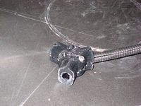
Cable Loom Y splitter by piercet
...sically just a y splitter for cable loom (the plastic split wire protection stuff. it takes 3 heat set m3 inserts and 3 m3 bolts.
thingiverse
free
Taz 6 Bed Anchor for Cable chain by piercet
...that replaces the stock cable wire loom anchor with an anchor point for a cable chain on the taz 6. it uses the same frame anchor
thingiverse
free
A printable digital box for Pikko by piercet
...shouse.com/box/ . she says we don't get a real box with it, but now there is one so there, nyah! thbbt!!!!
anyways, itsa box!
thingiverse
free

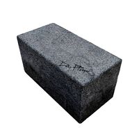
Sugar Skull with a Solid Base by piercet
... for decoration.
photo used courtesy travis elijah, all photo rights reside with him, thank you travis for the use of the photo!
thingiverse
free

STL file by piercet
...u can even juggle them if you want! be the first one on your block to prank people with the 3d printing equivalent of a rickroll!
thingiverse
free
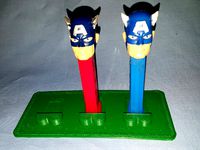
3 Pez Display stand base by piercet
...y to keep them from tipping over. so here it is. i took the original feet mount, added a baseplate, and then rounded the corners.
thingiverse
free
An Improved Flexible Filliment Extruder by piercet
...ot flexystruder. it should extrude flexible filliment faster, with greater retraction accuracy and less weight than alternatives.
Taz
3d_ocean
$19

TAZ RIGGED
...ax version only texture is used only for wb logo, taz dont need texture no special render engine needed, just unzip and render...
3d_export
$5

Taz character 3D Model
...taz character 3d model
3dexport
taz toon character cartoon
taz character 3d model supercigale 22095 3dexport
cg_studio
$10

Taz 3D3d model
...taz 3d3d model
cgstudio
.3ds .max - taz 3d 3d model, royalty free license available, instant download after purchase.
cg_studio
$15

Taz Rigged3d model
...ged3d model
cgstudio
.3ds .fbx .max .obj - taz rigged 3d model, royalty free license available, instant download after purchase.
3d_export
$10

Taz Toy Calendar 3D Model
... 3d model
3dexport
taz toy calendar day month year looney tunes cartoon kid child
taz toy calendar 3d model nkfrds 49687 3dexport
3d_export
$10

Taz Tasmanian Devil RIGGED 3D Model
...y tunes anime bunny rigged material fantasy creature diable dessin
taz tasmanian devil rigged 3d model supercigale 28390 3dexport
3d_export
$19

Thylacine 3D Model
...animalia chordata mammalia marsupial dog extinct animals tiger tassie taz thylacine 3d model poly3dmodels 90790...
3d_export
$12

Bowl Decorated 3D Model
...bowl decorated 3d model 3dexport bowl tazn elements ceramics kitchen plastic cup container decorative cake biscuits...
3ddd
$1

Crate & Barrel Serveware
...crate & barrel поднос -http://www.crateandbarrel.com/feast-platter/s186961 набор ножей для сыра -http://www.crateandbarrel.com/tazcheese-knife-3-piece-set/s681377 бокал...
thingiverse
free
TAZ by Taz8373
...taz by taz8373
thingiverse
my 1st print
Wobble
design_connected
$16

Wobble Chess Set
...wobble chess set
designconnected
umbra wobble chess set computer generated 3d model. designed by mumma, adin.
turbosquid
$25

Wobble chess set
... available on turbo squid, the world's leading provider of digital 3d models for visualization, films, television, and games.
cg_studio
$45

Wobble Chess Set3d model
...model
cgstudio
.max .3ds .lwo .obj - wobble chess set 3d model, royalty free license available, instant download after purchase.
3d_export
$23

Wobble chess set 3D Model
... game play pawn fun logic logical wood checker hobby hobbies sport wobble
wobble chess set 3d model energyoverflow 63990 3dexport
turbosquid
$105

Minature Wobble Steam Engine
...inature wobble steam engine for download as 3ds, max, and obj on turbosquid: 3d models for games, architecture, videos. (1298507)
3d_export
$75
Minature Wobble Steam Engine 3D Model
...er flywheel crankshaft pistol cylinder power energy compressed air
minature wobble steam engine 3d model plutonius 30906 3dexport
cg_studio
$75
Minature Wobble Steam Engine3d model
...io
.3ds .max .obj .wrl - minature wobble steam engine 3d model, royalty free license available, instant download after purchase.
cg_studio
$59

Wobble Chess and Timer Set3d model
...udio
.obj .lwo .max .3ds - wobble chess and timer set 3d model, royalty free license available, instant download after purchase.
3d_export
$5

Wobbling disk mechanism
...d. it is designed in solid works. i can add the other mechanism that you need on this model, or you can do it easily on your own.
3ddd
free

Шахматы
...шахматы 3ddd adin , mumma , wobble , шахматы моделил по картинке.оригинальное название - wobble chess...
Anti
3d_export
$5

Anti stress kit
...anti stress kit
3dexport
anti stress kit wall sign
turbosquid
$5
Anti-aircraft
... available on turbo squid, the world's leading provider of digital 3d models for visualization, films, television, and games.
3d_export
$5

Anti stapler 3D Model
...anti stapler 3d model
3dexport
staples anti stapler анти степлер
anti stapler 3d model seemoonlight 69602 3dexport
archive3d
free

Anti-aircraft 3D Model
...litary equipment
anti-aircraft m730a1 n020711 - 3d model (*.3ds) for exterior 3d visualization.
3d_export
$5
anti-vandal unit nofer
...anti-vandal unit nofer
3dexport
anti-vandal unit nofer
turbosquid
$3
Anti gravity drone
...
royalty free 3d model anti gravity drone for download as obj on turbosquid: 3d models for games, architecture, videos. (1311361)
turbosquid
$1
Anti airplane Missile
...yalty free 3d model anti airplane missile for download as fbx on turbosquid: 3d models for games, architecture, videos. (1274540)
turbosquid
$1
Anti-Terrorist Barrier
...e 3d model anti-terrorist barrier for download as jpg and obj on turbosquid: 3d models for games, architecture, videos. (1348463)
3d_ocean
$8

Sunsilk Anti Dandruff
...i dandruff sunsilk bottle sunsilk pack sunsilk product sunsilk shampoo
sunsilk anti dandruff is sunsilk shampoo 3d model product.
3d_ocean
$3
Anti Tank Barrier
...oly count: 476 polys - formats: max /obj /fbx - high detail was preserved with 1024×1024 textures - maps included ( all in 102...
6
3d_export
$18

tulip 6
...tulip 6
3dexport
tulip 6
3d_export
$5
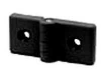
hinge 6
...hinge 6
3dexport
hinge 6
3ddd
$1

MASIERO / FLASHWOOD STL 6 + 6
...6
3ddd
masiero
торшер flashwood stl 6 + 6 фабрики masiero
http://www.masierogroup.com/c87_697/it/flashwood%20stl%206%20+%206.ashx
turbosquid
$39

A-6
... available on turbo squid, the world's leading provider of digital 3d models for visualization, films, television, and games.
3ddd
$1
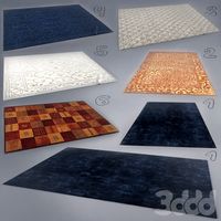
6 ковров
...6 ковров
3ddd
ковры , ковер
6 ковров
turbosquid
$12

Calligraphic Digit 6 Number 6
...hic digit 6 number 6 for download as max, obj, fbx, and blend on turbosquid: 3d models for games, architecture, videos. (1389336)
turbosquid
$19

Case For Phone 6 Girl 6
... available on turbo squid, the world's leading provider of digital 3d models for visualization, films, television, and games.
3ddd
free

IPhone 6
... 6
3ddd
apple , iphone , телефон
apple iphone 6
3ddd
$1

Люстра Masiero classica 6145 6+6
... masiero classica 6145 6+6
3ddd
masiero
люстра - masiero
каталог -сlassica
артикул - 6145 6+6
диаметр - 1300 мм
высота - 600 мм
3ddd
$1

Pillows #6
...pillows #6
3ddd
подушка
pillows #6
3ds max 2011, fbx + textures