GrabCAD
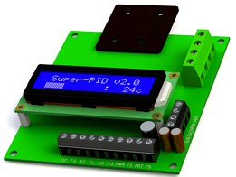
SuperPID v2.0 Closed-loop Router Speed Controller
by GrabCAD
Last crawled date: 1 year, 11 months ago
Super-PID (http://www.vhipe.com/product-private/SuperPID-Home.htm) is a closed loop speed controller that allows low-cost 1/4" and 1/2" routers to be used as speed-regulated spindles.
The addition of a Super-PID to your router setup allows the use of lower cutting RPM, quiet operation, exact regulated speeds and gives massive power improvements when operating 1/4" and 1/2" routers at low speeds.
Super-PID uses a reflective optical infra-red sensor that is simply pointed at the router output shaft and detects a spot of white paint on the shaft. This enables closed-loop speed control and a microprocessor chip inside the Super-PID executes an industrial style P.I.D. algorithm to give precise speed control with dramatically increased power at low and medium revs.
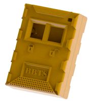
I modeled the board using the dimensional drawing provided in the SuperPID manual, as well as physically measuring the one I purchased. The main features of the model are the mounting hole locations, the head sink plate, the terminal blocks (modeled as bodies, c/w solidworks routing points) and the LCD standoffs. All of these items are dimensionally accurate and can be used to design enclosures or boxes for the SuperPID. I started modeling other features, such as capacitors and integrated circuits, but decided it was unnecessary for my purposes (mounting in a box).
I used the LCD screen model from Anders Lohmann (https://grabcad.com/library/16x2-character-lcd-display-1) which was absolutely fantastic, if just a bit heavy. I made some changes to the screen by deleting the original feature showing the entire LCD board dots, and replaced it with my own. I used the led calculator font, downloaded from here (http://www.dafont.com/led-calculator.font) and created a cut feature using this text. I also fiddled a bit with the transparency and colors of all three pieces of screen glass to give the color of screen and text I was looking for.
The SuperPID assembly (SuperPID-v2.sldasm) contains 3 parts --
SuperPID v2.sldprt (board)
DFRobot_1602 (LCD screen)
16pin_header.sldprt
The other part (SuperPID-v2_board assembly) and the step file are the entire assembly exported as a part and a step file, respectively.
The addition of a Super-PID to your router setup allows the use of lower cutting RPM, quiet operation, exact regulated speeds and gives massive power improvements when operating 1/4" and 1/2" routers at low speeds.
Super-PID uses a reflective optical infra-red sensor that is simply pointed at the router output shaft and detects a spot of white paint on the shaft. This enables closed-loop speed control and a microprocessor chip inside the Super-PID executes an industrial style P.I.D. algorithm to give precise speed control with dramatically increased power at low and medium revs.
I modeled the board using the dimensional drawing provided in the SuperPID manual, as well as physically measuring the one I purchased. The main features of the model are the mounting hole locations, the head sink plate, the terminal blocks (modeled as bodies, c/w solidworks routing points) and the LCD standoffs. All of these items are dimensionally accurate and can be used to design enclosures or boxes for the SuperPID. I started modeling other features, such as capacitors and integrated circuits, but decided it was unnecessary for my purposes (mounting in a box).
I used the LCD screen model from Anders Lohmann (https://grabcad.com/library/16x2-character-lcd-display-1) which was absolutely fantastic, if just a bit heavy. I made some changes to the screen by deleting the original feature showing the entire LCD board dots, and replaced it with my own. I used the led calculator font, downloaded from here (http://www.dafont.com/led-calculator.font) and created a cut feature using this text. I also fiddled a bit with the transparency and colors of all three pieces of screen glass to give the color of screen and text I was looking for.
The SuperPID assembly (SuperPID-v2.sldasm) contains 3 parts --
SuperPID v2.sldprt (board)
DFRobot_1602 (LCD screen)
16pin_header.sldprt
The other part (SuperPID-v2_board assembly) and the step file are the entire assembly exported as a part and a step file, respectively.
Similar models
grabcad
free

SuperPID Custom Speed Control Box
...double pole. all models from others imported and modified to meet my needs for this project. all materials and appearances by me.
grabcad
free

Super PID 2
...on and mounting holes. measure your display before using the display in the model. the one modeled shipped with my superpid unit.
thingiverse
free

SuperPID Case by dkrider
...s provided for entertainment purposes only and any harm you receive from messing around with mains electricity is your own fault.
grabcad
free

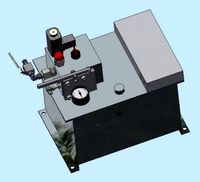
Hydraulic Steering Shaft O-Ring Gauge
... result feeds to an on-screen guided assembly control to ensure that operators only pass correctly assembled units down the line.
grabcad
free

ball on plate PID controller
...s the solidworks for a control project using th pid controller to balance a ball on touch screen 9 inch using servos to control .
grabcad
free

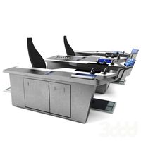
SL_ST FLEXURE PID DEMO STAND-00
...a vca. based on the smooth l7251 controller or similar ...
thingiverse
free

raspberry pi 7" LCD case by saswatahira
...cutout for connections to controller for raspberry pi or similar single board...
thingiverse
free

DIY LCD screen Frame Parts by shehul1991
...es will help you in your project.
some of the files are related to my controller board only. make sure before you print anything.
thingiverse
free

Lcd controller board MNT68676 v.2a by SSerg
...lcd controller board mnt68676 v.2a by sserg
thingiverse
dimensional model for case development.
thingiverse
free

LCD monitor from laptop LCD screen v2
...t photo)
panels, supported by this controller:
b156han01.2
n156hge-eb1
b156htn03.6
b156htn03.4
b156htn03.0
ltn156hl06-c01
lgd0519
Superpid
thingiverse
free
SuperPID Case by dkrider
...s provided for entertainment purposes only and any harm you receive from messing around with mains electricity is your own fault.
thingiverse
free

MPCNC DW-660 SuperPID RPM Sensor bracket
...mperature resistance. with the final version the spindle temp stayed low and has worked reliably for roughly 40 hours of cutting.
grabcad
free
SuperPID Custom Speed Control Box
...double pole. all models from others imported and modified to meet my needs for this project. all materials and appearances by me.
grabcad
free
Super PID 2
...in the model. the one modeled shipped with my superpid ...
grabcad
free

Hi-Box Electronics Box - EL-AG-1318-B
...is rohs and reach compliant. box was purchased here: http://www.vhipe.com/product-private/superpidproducts-and-accessories.htm manufacturer website here: http://www.dsehibox.com/ and here:...
Router
archibase_planet
free

Router
...er wi-fi router modem wi-fi modem pc equipment
router wi-fi modem n091015 - 3d model (*.gsm+*.3ds) for interior 3d visualization.
turbosquid
$7

Router
...uid
royalty free 3d model router for download as fbx and obj on turbosquid: 3d models for games, architecture, videos. (1642809)
3d_export
$10
cnc router
...cnc router
3dexport
prototipe cnc router
turbosquid
$5

Router
...free 3d model router for download as blend, fbx, obj, and stl on turbosquid: 3d models for games, architecture, videos. (1632831)
3d_ocean
$9

4G Router
...4g router
3docean
3d 4g broadband connection internet models real router
3d,model,router,modelings,broadband,internet
3d_export
$15

Router 3D Model
...router 3d model
3dexport
router switch network computer
router 3d model digitaldust 19088 3dexport
3ddd
free

Tplink Router
... маршрутизатор , tp-link
this is a tplink router 3dmodel. its photo based. game ready.
3d_export
$5

Wifi router
...e minimalistic design has contacts in ports and leds rendered in blender, cycles verts 33.449 faces 30.985 tris 66.244 connection
archive3d
free

Router 3D Model
...pc equipment
router wi-fi modem n091015 - 3d model (*.gsm+*.3ds) for interior 3d visualization.
turbosquid
$10

Palm Router
...
royalty free 3d model palm router for download as ma and fbx on turbosquid: 3d models for games, architecture, videos. (1307277)
Loop
design_connected
$13

Loop
...loop
designconnected
coro loop computer generated 3d model. designed by wright, gala.
turbosquid
$9

Loop
...op
turbosquid
royalty free 3d model loop for download as c4d on turbosquid: 3d models for games, architecture, videos. (1344531)
3d_export
$5

Loop
...loop
3dexport
3d_export
$5

Furniture loop
...furniture loop
3dexport
furniture loop salice
turbosquid
$1

Loop
... available on turbo squid, the world's leading provider of digital 3d models for visualization, films, television, and games.
3ddd
free

Loop Cair
...loop cair
3ddd
loop
металлический изящный стул
3ddd
$1

Loop
...loop
3ddd
serralunga , лавка
лавка serralunga
3ddd
$1

Ulivi Loop
... ulivi , loop
cтол loop фабрики ulivi (италия)
длина 140
ширина 80
высота 42
3ddd
$1

LOOP TABLE
...loop table
3ddd
neocraft
neo/craft | loop collectionloop tablerectangular steel and wood table
3ddd
$1

LOOP CHAIR
...ruction with a futuristic character. it is all about flowing forms, and creating a rhythm through its elegant volumes and shapes.
V2
3d_export
free
Lamp v2
...lamp v2
3dexport
lamp v2 with solar panel
3d_export
$5

hammerhead v2
...hammerhead v2
3dexport
razer hammerhead v2 headphones, modeled in cinema 4d, render in corona
3d_export
$5

manometer v2
...manometer v2
3dexport
3d_export
$5

potato v2
...potato v2
3dexport
turbosquid
$52

Lifebuoys v2
...squid
royalty free 3d model lifebuoys v2 for download as fbx on turbosquid: 3d models for games, architecture, videos. (1560870)
turbosquid
$2

Mask v2
...turbosquid
royalty free 3d model mask v2 for download as stl on turbosquid: 3d models for games, architecture, videos. (1527741)
turbosquid
free
Flashlight V2
...d
free 3d model flashlight v2 for download as , obj, and fbx on turbosquid: 3d models for games, architecture, videos. (1663559)
turbosquid
$29
Thanos v2
...
royalty free 3d model thanos v2 for download as ztl and obj on turbosquid: 3d models for games, architecture, videos. (1651077)
turbosquid
$29
Titan v2
...d
royalty free 3d model titan v2 for download as ztl and obj on turbosquid: 3d models for games, architecture, videos. (1540228)
turbosquid
$29
Frieza v2
...
royalty free 3d model frieza v2 for download as ztl and obj on turbosquid: 3d models for games, architecture, videos. (1701238)
Speed
turbosquid
$50

speed
... available on turbo squid, the world's leading provider of digital 3d models for visualization, films, television, and games.
turbosquid
$50

speed
... available on turbo squid, the world's leading provider of digital 3d models for visualization, films, television, and games.
turbosquid
free

speed
... available on turbo squid, the world's leading provider of digital 3d models for visualization, films, television, and games.
3d_ocean
$8
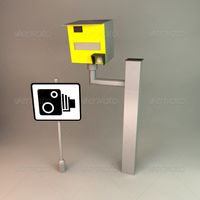
Speed Camera
...model is separate and named appropriately. this is perfect for any type of scene from a road side, architectural or motorway s...
turbosquid
$25

Speed Buggy
...urbosquid
royalty free 3d model speed buggy for download as on turbosquid: 3d models for games, architecture, videos. (1209512)
turbosquid
$4

Speed Sign
...turbosquid
royalty free 3d model speed sign for download as on turbosquid: 3d models for games, architecture, videos. (1251518)
3d_export
$10

variable speed bicycle
...variable speed bicycle
3dexport
variable speed bicycle
3d_export
$5
High - speed aircraft
...high - speed aircraft
3dexport
high speed plane
turbosquid
$185

Speed Boat
... free 3d model speed boat for download as skp, blend, and obj on turbosquid: 3d models for games, architecture, videos. (1606216)
turbosquid
$5

Speed bag
...y free 3d model speed bag for download as blend, obj, and stl on turbosquid: 3d models for games, architecture, videos. (1577878)
0
turbosquid
$12

Calligraphic Digit 0 Number 0
...hic digit 0 number 0 for download as max, obj, fbx, and blend on turbosquid: 3d models for games, architecture, videos. (1389318)
3d_export
$6
set-0
...set-0
3dexport
turbosquid
$6

hedge 0
...yalty free 3d model hedge 0 for download as max, obj, and fbx on turbosquid: 3d models for games, architecture, videos. (1450353)
turbosquid
$5

Nuber 0
...oyalty free 3d model nuber 0 for download as ma, obj, and fbx on turbosquid: 3d models for games, architecture, videos. (1564674)
turbosquid
$22

0.jpg
... available on turbo squid, the world's leading provider of digital 3d models for visualization, films, television, and games.
turbosquid
free

Steam Locomotive Fowler 4F 0-6-0
... available on turbo squid, the world's leading provider of digital 3d models for visualization, films, television, and games.
turbosquid
$10

Liquid Number 0
... model liquid number 0 for download as c4d, 3ds, fbx, and obj on turbosquid: 3d models for games, architecture, videos. (1689919)
turbosquid
$45
Dragon360_perspShape_tmp.0.jpg
... available on turbo squid, the world's leading provider of digital 3d models for visualization, films, television, and games.
turbosquid
$8

Rocks Debris 0
... available on turbo squid, the world's leading provider of digital 3d models for visualization, films, television, and games.
3d_export
$18
wood-guardrail-fence 0
...wood-guardrail-fence 0
3dexport
wood-guardrail-fence 0<br>3ds max 2015
Controller
3d_ocean
$4
Controller TQFP32
...qfp32
3docean
chip controller cpu electronic gpu mcu micro controller silicon smd tqfp wafer
a micro controller in tqfp32 package
3d_ocean
$4
Controller TQFP44
...44
3docean
chip controller cpu electronic gpu mcu micro controller package smd tqfp tqfp44
a micro controller in a tqfp44 package
3d_export
$15
control unit
...control unit
3dexport
control unit
3ddd
$1
Yacht control
...yacht control
3ddd
yacht control
3d_export
$5
controle pgdm
...controle pgdm
3dexport
carcaca controle pgdm
turbosquid
free
controler
... available on turbo squid, the world's leading provider of digital 3d models for visualization, films, television, and games.
3ddd
$1

Control
...
http://www.schmitz-leuchten.de/html-ru/einzelleuchten-lampentyp-details.php?lamptype_no=700&group;=917&id;=731
3d_ocean
$4
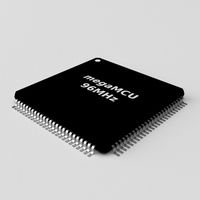
Controller TQFP100
...100
3docean
chip computer cpu electronic gpu mcu micro controller pin platine silicon wafer
a micro controller in tqfp100 package
3d_ocean
$4
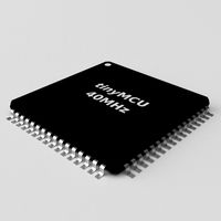
Controller TQFP64
...qfp64
3docean
chip computer cpu gpu mcu micro controller package silicon tqfp tqfp64 wafer
a micro controller in a tqfp64 package
3d_ocean
$7

Remote controller
... control switcher tv remote
remote controller for tv, sound systems etc easy to edit textures photo real rendered with mental ray
Closed
turbosquid
$35

Closed
... available on turbo squid, the world's leading provider of digital 3d models for visualization, films, television, and games.
turbosquid
$10

Closed baskets
...osquid
royalty free 3d model closed baskets for download as on turbosquid: 3d models for games, architecture, videos. (1683282)
turbosquid
$2

closed to dust
...uid
royalty free 3d model closed to dust for download as stl on turbosquid: 3d models for games, architecture, videos. (1403703)
turbosquid
$29

hands close
...e 3d model hands close for download as 3ds, obj, c4d, and fbx on turbosquid: 3d models for games, architecture, videos. (1442051)
turbosquid
$29

Closed Pinecone
... available on turbo squid, the world's leading provider of digital 3d models for visualization, films, television, and games.
turbosquid
$10

CLOSED~1.3DS
... available on turbo squid, the world's leading provider of digital 3d models for visualization, films, television, and games.
turbosquid
$1

Briefcase Closed
... available on turbo squid, the world's leading provider of digital 3d models for visualization, films, television, and games.
3d_export
$20

bank vault close
...bank vault close
3dexport
bank vault close
3d_export
$8

road closed sign
...road closed sign
3dexport
road closed sign
3d_export
$5

closed hand wheel
...closed hand wheel
3dexport
closed hand wheel