GrabCAD
Sun-pumped, ground-cooled condenser
by GrabCAD
Last crawled date: 1 year, 11 months ago
This is an entry for the NBD Nano competition at http://grabcad.com/challenges/countertop-atmospheric-water-generator .
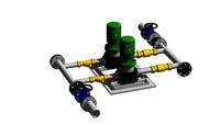
My suggestion is to coat the inside of a hose with the NBD Nano condenser surface. This will allow for an extremely simple and cheap design for an ultra-efficient water condenser that is "turbocharged" by the energy of the sun and by the vortex-mixing of the air inside the hose. The design described below should be many times more efficient than other designs that just rely on the breeze to bring moisture into contact with the NBD Nano condenser surface. Overall this design has very few parts, is quick and easy to set up, should produce high condensing efficiencies, and is almost arbitrarily scalable by just adding more materials. This design has no moving parts, and requires no external energy source other than sunlight. The design could be constructed out of completely recyclable materials.
By coating a hose with the NBD Nano surface and then passing air through the hose, rather than just exposing a condenser surface to a breeze, the proportion of a given volume of incoming airflow that is exposed to the surface is dramatically increased, because as air passes through a hose, it adheres to the surface of the hose, creating constant toroidal rolling vortices (like smoke rings, but more chaotic) along the length of the inside of the hose. (This principle is used in your body in the esophagus, to capture as much dust as possible on the mucus membranes before air enters the lungs.)
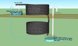
In my design I bury a coil of hose with NBD Nano lining underground, at a sufficient depth that the surrounding ground is much cooler than the air above ground. (This probably requires a depth of a meter or two; too deep and lifting water back up from that depth will require too much work.) The system draws air from an above-ground air intake down and past a buffer tank, then through the underground hose coil. Because the temperature underground is lower than the air temperature on sunny days, this will increase the efficiency of the condenser surface even further by cooling the air, increasing condensation. Above ground, another coil of hose, colored black and exposed to sunlight, is connected to the first coil such that when the sun heats the above-ground coil, the air inside it expands and rises, escaping from the air outlet at the end of the hose, which is at the highest point. This sun-powered "convection pump" creates the suction that pulls the air into the intake and through the below-ground cooling coil. (The above-ground portion of the hose does not need to be coated internally with the NBD Nano condenser surface if it will save on cost -- then again, using just one type of hose for the whole design may save on cost, even though the above-ground coil won't condense much water due to its internal temperature.)
And at the bottom of the below-ground cooling coil is a sealed water buffer tank. As air condenses in the cooling coil, it flows down the coil (in the opposite direction from the rising air) and into the buffer tank. The purpose of this tank is to allow air from the intake to continue to flow up through the cooling coil even if a significant amount of water has flowed down out of the coil.
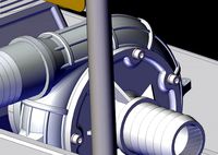
A smaller-diameter hose runs into the air outlet hose at an angle incident to the flow direction (the smaller white tube in the model), and this creates suction up through the pipe through the Venturi effect. This "Venturi pump" is used to siphon water up from the underground buffer tank into an above-ground collection tank along an even smaller-diameter tube (shown in blue in the diagram). (The diameter of this siphon tube is small so that the suction force required to lift water from the lower tank to the upper tank is reduced.)
Regarding the requirement "Using the metric of 3L/m^2/hr of water at 70% RH, the proposed device must be able to produce a minimum of 1/2 L per hour": The total surface area of the inside of a hose of given length L and diameter D can be calculated quite simply as (pi * L * D), and this can be used to achieve any desired water production rate, by simply adding more hose if needed. To produce 1/2L/hr, you would need 1/6 m^2 of condenser surface, which would require 1.8m of hose below ground if the hose were 3cm in diameter. Note however that by cooling the air underground, the standard rate of 3L/m^2/hr for open-air designs will be able to be exceeded, so the proposed mechanism should be more efficient than many other designs. Using the open air rate though, for circular coils of hose of diameter 1m, one coil revolution requires 3.14m of hose, producing 0.9L/hr. Ten underground coil loops will therefore produce up to 9L/hr, although the upper coil revolutions will become less efficient as the air dries out -- tests would need to be run to see how many times the hose can be coiled before the point of diminishing returns. (In general, the right combination of hose diameter, below and above ground hose length, the diameter of the water transport hose and tank sizes will need to be tested to find the optimal parameters for a given combination of air temperature, humidity and sunlight strength.)
In terms of practical construction: the coils could be created by digging a hole and setting four upright sticks or poles in a square configuration, then winding the hose around them, and then re-filling with dirt around and within the bottom coil, after which the top coil is wound around the poles above ground.
N.B. 1: You could make this system even more efficient by inverting the bottom coil, so that both air and water flow downwards towards the buffer tank in the bottom coil, and then upwards through the above-ground coil. Not only would air and water now be flowing in the same direction (downwards), reducing friction and facilitating water flow, but as the air flows through the condenser coil, it cools, so the air would now be heading in the direction it naturally wants to head in as it cools, i.e. downwards.)
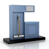
N.B. 2: I created this model in SketchUp and exported to IGES as requested in the competition requirements. Unfortunately, I don't have an IGES viewer, so I can't verify if the export worked well. Therefore, I am also providing the model in Sketchup and Collada format, as well as a Sketchup rendering in PNG format.
My suggestion is to coat the inside of a hose with the NBD Nano condenser surface. This will allow for an extremely simple and cheap design for an ultra-efficient water condenser that is "turbocharged" by the energy of the sun and by the vortex-mixing of the air inside the hose. The design described below should be many times more efficient than other designs that just rely on the breeze to bring moisture into contact with the NBD Nano condenser surface. Overall this design has very few parts, is quick and easy to set up, should produce high condensing efficiencies, and is almost arbitrarily scalable by just adding more materials. This design has no moving parts, and requires no external energy source other than sunlight. The design could be constructed out of completely recyclable materials.
By coating a hose with the NBD Nano surface and then passing air through the hose, rather than just exposing a condenser surface to a breeze, the proportion of a given volume of incoming airflow that is exposed to the surface is dramatically increased, because as air passes through a hose, it adheres to the surface of the hose, creating constant toroidal rolling vortices (like smoke rings, but more chaotic) along the length of the inside of the hose. (This principle is used in your body in the esophagus, to capture as much dust as possible on the mucus membranes before air enters the lungs.)
In my design I bury a coil of hose with NBD Nano lining underground, at a sufficient depth that the surrounding ground is much cooler than the air above ground. (This probably requires a depth of a meter or two; too deep and lifting water back up from that depth will require too much work.) The system draws air from an above-ground air intake down and past a buffer tank, then through the underground hose coil. Because the temperature underground is lower than the air temperature on sunny days, this will increase the efficiency of the condenser surface even further by cooling the air, increasing condensation. Above ground, another coil of hose, colored black and exposed to sunlight, is connected to the first coil such that when the sun heats the above-ground coil, the air inside it expands and rises, escaping from the air outlet at the end of the hose, which is at the highest point. This sun-powered "convection pump" creates the suction that pulls the air into the intake and through the below-ground cooling coil. (The above-ground portion of the hose does not need to be coated internally with the NBD Nano condenser surface if it will save on cost -- then again, using just one type of hose for the whole design may save on cost, even though the above-ground coil won't condense much water due to its internal temperature.)
And at the bottom of the below-ground cooling coil is a sealed water buffer tank. As air condenses in the cooling coil, it flows down the coil (in the opposite direction from the rising air) and into the buffer tank. The purpose of this tank is to allow air from the intake to continue to flow up through the cooling coil even if a significant amount of water has flowed down out of the coil.
A smaller-diameter hose runs into the air outlet hose at an angle incident to the flow direction (the smaller white tube in the model), and this creates suction up through the pipe through the Venturi effect. This "Venturi pump" is used to siphon water up from the underground buffer tank into an above-ground collection tank along an even smaller-diameter tube (shown in blue in the diagram). (The diameter of this siphon tube is small so that the suction force required to lift water from the lower tank to the upper tank is reduced.)
Regarding the requirement "Using the metric of 3L/m^2/hr of water at 70% RH, the proposed device must be able to produce a minimum of 1/2 L per hour": The total surface area of the inside of a hose of given length L and diameter D can be calculated quite simply as (pi * L * D), and this can be used to achieve any desired water production rate, by simply adding more hose if needed. To produce 1/2L/hr, you would need 1/6 m^2 of condenser surface, which would require 1.8m of hose below ground if the hose were 3cm in diameter. Note however that by cooling the air underground, the standard rate of 3L/m^2/hr for open-air designs will be able to be exceeded, so the proposed mechanism should be more efficient than many other designs. Using the open air rate though, for circular coils of hose of diameter 1m, one coil revolution requires 3.14m of hose, producing 0.9L/hr. Ten underground coil loops will therefore produce up to 9L/hr, although the upper coil revolutions will become less efficient as the air dries out -- tests would need to be run to see how many times the hose can be coiled before the point of diminishing returns. (In general, the right combination of hose diameter, below and above ground hose length, the diameter of the water transport hose and tank sizes will need to be tested to find the optimal parameters for a given combination of air temperature, humidity and sunlight strength.)
In terms of practical construction: the coils could be created by digging a hole and setting four upright sticks or poles in a square configuration, then winding the hose around them, and then re-filling with dirt around and within the bottom coil, after which the top coil is wound around the poles above ground.
N.B. 1: You could make this system even more efficient by inverting the bottom coil, so that both air and water flow downwards towards the buffer tank in the bottom coil, and then upwards through the above-ground coil. Not only would air and water now be flowing in the same direction (downwards), reducing friction and facilitating water flow, but as the air flows through the condenser coil, it cools, so the air would now be heading in the direction it naturally wants to head in as it cools, i.e. downwards.)
N.B. 2: I created this model in SketchUp and exported to IGES as requested in the competition requirements. Unfortunately, I don't have an IGES viewer, so I can't verify if the export worked well. Therefore, I am also providing the model in Sketchup and Collada format, as well as a Sketchup rendering in PNG format.
Similar models
grabcad
free

Solar Updraft Water Generator
... area of the filter is about 870,000 mm^2 or .87m^2. the condensate will then flow down the tube into a container of your choice.
grabcad
free

Nano Aquamist
... technology is highly profitable for its characteristics and generate a considerable reduction in the maintenance of water tanks.
grabcad
free

train bogie
...f fog and also in desert area.
due to huge surface it can store a very good quantity in tank which would be used for many purpose
cg_trader
$20

AT vertical flow reedbed
...n the right. see the 'purchasing_the_models' link at appropedia's at_cad_team for additional information on the model
grabcad
free

Weather Balloon Water Generator
...rnal structure like a blimp.
and sorry i couldn’t the step or iges files, i’m a student and only have the sw student design kit
grabcad
free

Modified Air Cooler
...modified air cooler
grabcad
its a modified air cooler with a condenser coil on which water will be spread to cool it further
grabcad
free

Water generator
...level. this effect is greatly increased by solar powered high efficient fan. most of the parts can be made of recyclable plastic.
grabcad
free

agriculture
... to water store tank.
this can be made on huge surface so water level may increase.
this water will again use in plant watering.
grabcad
free

Nano Oasis
...umidity as water and direct it to the plant. applicable as 'lazy' plant care solution or for desert re-green enthusiasts.
grabcad
free

Water Generatro
...the water drips down into a catch basin and then into a water outlet pipe for collection.
created using solidworks® version 2007
Condenser
3d_export
$5

condensed milk
...condensed milk
3dexport
condensed milk, real russian condensed milk, v ray is present
turbosquid
$1

condensed milk
...d
royalty free 3d model condensed milk for download as blend on turbosquid: 3d models for games, architecture, videos. (1561828)
turbosquid
$7

Tin with Condensation
...model tin with condensation for download as max, fbx, and obj on turbosquid: 3d models for games, architecture, videos. (1688928)
turbosquid
$18

Condenser Microphone
... available on turbo squid, the world's leading provider of digital 3d models for visualization, films, television, and games.
3d_ocean
$2

Condensator
...an. if you need something like this, please, check out my other items or buy a whole pack of all electrical parts that i made....
3d_export
$39

Condenser 3D Model
...quipment fan cooling loop
condenser 3d model download .c4d .max .obj .fbx .ma .lwo .3ds .3dm .stl sunshineweilian 105813 3dexport
3d_export
$150

Vacuum Condensate Unit 3D Model
...ate unit 3d model
3dexport
vacuum condensate unit vcud water suction
vacuum condensate unit 3d model briancrosdale 76892 3dexport
3d_ocean
$5

Variable Condensator
...an. if you need something like this, please, check out my other items or buy a whole pack of all electrical parts that i made....
turbosquid
$20

Condenser Water Filtration System
...d model condenser water filtration system for download as max on turbosquid: 3d models for games, architecture, videos. (1274956)
3d_export
$5

microphone condenser microphones stand
...microphone condenser microphones stand
3dexport
Sun
3d_export
$5

sun oracle sun fire x4170
...sun oracle sun fire x4170
3dexport
sun oracle sun fire x4170
3d_export
$5

sun
...sun
3dexport
3d_export
$20

sun
...beautifully. ~ 100,000 for the sun ring ~ 100,000 for the sun face everything in a convenient obj format. dragonwahlnus*gmail*com
turbosquid
free

Sun
...sun
turbosquid
free 3d model sun for download as max on turbosquid: 3d models for games, architecture, videos. (1482222)
3d_ocean
$3

Sun
...ine. .blend end .obj files included. uv unwrapped and material, texture is applied. texture size is 1024×512. sun glow effects...
turbosquid
$25

Sun
...sun
turbosquid
royalty free 3d model sun for download as fbx on turbosquid: 3d models for games, architecture, videos. (1635393)
turbosquid
$3

Sun
...n
turbosquid
royalty free 3d model sun for download as blend on turbosquid: 3d models for games, architecture, videos. (1484318)
3d_export
$12

sun model
...sun model
3dexport
3d model sun prop.
turbosquid
free

The Sun
... available on turbo squid, the world's leading provider of digital 3d models for visualization, films, television, and games.
3d_export
$5

symbol sun
...symbol sun
3dexport
3 d model symbol sun
Pumped
3d_export
$5
pump
...pump
3dexport
pump
archibase_planet
free
Pump
...pump
archibase planet
petrol pump petrol station gas station
pump - 3d model (*.gsm+*.3ds) for interior 3d visualization.
3d_ocean
$8

Pumps
...ps
3docean
girls heels high kicks pumps shoes stilettos womens
womens high heels, pumps or stilettos. polygon model – no textures
3ddd
free
Pump
...ump
3ddd
pump , versus
производитель: versus
модель: pumphttp://www.versus.as/
turbosquid
$3
Pumps
...s
turbosquid
royalty free 3d model pumps for download as skp on turbosquid: 3d models for games, architecture, videos. (1275250)
3d_export
$5
pump
...pump
3dexport
turbosquid
$39
Realistic Water pump SYLLENT PUMP
...realistic water pump syllent pump for download as max and obj on turbosquid: 3d models for games, architecture, videos. (1312864)
turbosquid
$150

Pumpe
...yalty free 3d model pumpe for download as ige, blend, and stl on turbosquid: 3d models for games, architecture, videos. (1284318)
3d_export
$10
gear pump
...gear pump
3dexport
it is a gear pump in iges format
turbosquid
$19
Old Water Pumps Gas Pumps
...pumps gas pumps for download as 3ds, obj, fbx, blend, and dae on turbosquid: 3d models for games, architecture, videos. (1207997)
Ground
3d_export
$13

ground
...ground
3dexport
modeling of ground... - maya - v-ray - car - animation
turbosquid
$3

Ground
...
turbosquid
royalty free 3d model ground for download as max on turbosquid: 3d models for games, architecture, videos. (1695083)
turbosquid
$3

Ground
...oyalty free 3d model ground for download as max, obj, and stl on turbosquid: 3d models for games, architecture, videos. (1473656)
3d_ocean
$2

Ground Bark
...ground bark
3docean
bark ground seamless texture tileable tiled
tileable, ground bark 2048×2048px high quality 300 dpi
vizpark
$50

Real Grounds
...ew set of 15 3d scanned ground textures for architectural visualization or games, fully tileable with resolution of 8k, 4k or 2k.
3d_export
$5

ground 3D Model
...ground 3d model
3dexport
ground textures
ground 3d model godzik 3022 3dexport
turbosquid
$6

ground lamp
...osquid
royalty free 3d model ground lamp for download as c4d on turbosquid: 3d models for games, architecture, videos. (1492655)
turbosquid
$1

Tree with ground
...d
royalty free 3d model tree with ground for download as obj on turbosquid: 3d models for games, architecture, videos. (1152744)
3d_ocean
$6

Ground. Gravel path.
...d textures. in this case, the texture of gravel paths. there are three maps in this archive: 1. 5000×5000 ground texture for c...
turbosquid
$99

Sport Ground
... free 3d model sport ground for download as max, obj, and fbx on turbosquid: 3d models for games, architecture, videos. (1397967)
Cooled
turbosquid
free

Cool Inc. Cool Box
... available on turbo squid, the world's leading provider of digital 3d models for visualization, films, television, and games.
3d_export
$5

cool penguin
...cool penguin
3dexport
cool penguin
turbosquid
$1

cooling
... available on turbo squid, the world's leading provider of digital 3d models for visualization, films, television, and games.
3d_export
$26

cooling tower
...ers.<br>model with full detail in real size. all nodes and bolted connections are built. it was designed for nuclear power.
3ddd
$1

Mantra Cool
...14 версиях и obj-файл, а также материал для включенного и для выключенного светильника. turbosmooth/meshsmooth при необходимости.
3d_export
$5

cool electric guitar
...cool electric guitar
3dexport
cool electric guitar
turbosquid
$5

Cooling glass
...quid
royalty free 3d model cooling glass for download as obj on turbosquid: 3d models for games, architecture, videos. (1193829)
turbosquid
$30

CPU Cooling
...royalty free 3d model cpu cooling for download as max and fbx on turbosquid: 3d models for games, architecture, videos. (1386263)
turbosquid
$5

Cool CLoud
...
royalty free 3d model cool cloud for download as ma and obj on turbosquid: 3d models for games, architecture, videos. (1572300)
3d_export
$5

table cooling fan
...table cooling fan
3dexport
table cooling fan made of black plastic. individual small size cooling fan for office desk.