Thingiverse
S.T.E.V.E - CoreXY 3D Printer by Adam_V3D
by Thingiverse
Last crawled date: 3 years ago
Want to know more about the design and assembly process?https://www.youtube.com/playlist?list=PLWL37f39O8e8jSmrYGKiWX6iMkNlrfwSp
Join the Facebook Group for discussion + Q&A + Future updates and upgradeshttps://www.facebook.com/groups/266957403761491/
See the full Bill of Materials with supplied links here: https://docs.google.com/spreadsheets/d/1FVdSh7WRvvxo3kc_i1Jvbl6kwNt3XSbQIA1PcNw0xOk/edit#gid=0 (some affiliate links included but buy from wherever you feel comfortable)
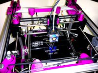
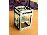
S.T.E.V.E is an open source, single extruder, easy to modify 3D printer with a approx 240mm cubed build volume and CoreXY Kinematics. When starting to design S.T.E.V.E I just wanted to learn more about the CoreXY kinematics but things got out of hand, one thing lead to another, and I ended up designing an entire printer that I wanted to share.
He was designed with the intention of every part being easy to purchase or print, and easy to build with assistance of detailed instructions with very little needed in terms of tools. (For best results a drill and 3.5mm bit plus crimping tool for red crimp terminals would be ideal. You can probably survive without.) The obvious allen keys are also needed.
Instructions are currently in the form of PDF drawings and an extensive video guide. All the video links are down below. Some show some information about the design process, while the others explain how to assemble the printer.
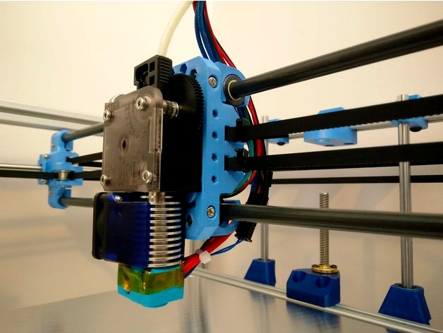
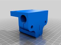
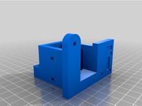
One of S.T.E.V.E's most unique features is the gantry head assembly. It ensures that the centre of mass of the stepper motor is aligned as closely as possible to the rods to reduce torque on the bearings and improve print quality. The same assembly provides a modular system for adding, changing or removing different features from around the hot end such as cable management, fans, bed sensors etc.
While this isn't a remix, i'll give some credit to Tech2C and his hypercube printer. I did borrow a couple of design aspects such as the clamps used for round rods.
Frame
S.T.E.V.E's frame is constructed from standard 6mm slot 2020 aluminium extrusion, held together with M5 x 8mm Button head screws and 90 degree angle brackets. All easy to get and easy to assemble.
One key design feature of S.T.E.V.E is that all the components are kept within the rigid 2020 aluminium frame so that it is simple to enclose the printer to form a heated chamber for printing of more exotic materials. (heat resistant plastic parts also recommended)
Steppers
S.T.E.V.E uses a total of 5 NEMA 17 stepper motors, a 13Ncm pancake stepper for the extruder, 4 45Ncm D shaft steppers for the X, Y and Z motion.
Control Board
The selected control board for version 0.1 of S.T.E.V.E is the RAMPS 1.4. This will be upgraded in the future as RAMPS was mostly for prototyping.
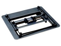
Heated Bed
The bed is 6mm tool plate aluminium which is ideal as it has high thermal conductivity and won’t warp overtime becuase of the way it was manufactured. The Heating is provided by a 330W 230V silicon heater with a built in thermal cut off at 180C for safety (set RAMPS max to 150C).
SSR
Because the bed heater is powered through mains voltage a Solid state relay is used to control power to the bed. The low voltage side of the SSR is attached to the control board as normal and acts like a switch.
Hotend and Extruder
S.T.E.V.E uses the E3D v6 full metal universal hot end and titan extruder with a 13Ncm stepper motor to provide a lightweight, versatile and reliabile print head.
Power Supply
Since the power supply is only for the stepper motors and hot end, there is no need for 300-400W power supplies. A high quality 12V unit that can supply 80-100W should be more than enough. Closet to 100W if you want some LEDs in there too.
Special Note: Recently i have noticied that the aluminium rods for X and Y are a little too flexible. I am going to test putting Steel rods on the Y axis and see how that does. Might have to upgrade the X axis to 10mm Aluminium or 8mm steel for rigidity. Will keep you updated.
Special Note 2: Not sure what makes these notes special but i have tested with 8mm steel on the X and Y axis. I have had good results with 8mm steel rods on both axis.
Final Note: Work on STEVE mk2 is now starting. In order to finish off mk1 I have uploaded a zip file (STEVE update Parts) containing a number of files that I considered unfinished work. These are all parts I was working on and are probably usable but not necessarily better. Up to you what you decide to use but I thought I should share them.
Join the Facebook Group for discussion + Q&A + Future updates and upgradeshttps://www.facebook.com/groups/266957403761491/
See the full Bill of Materials with supplied links here: https://docs.google.com/spreadsheets/d/1FVdSh7WRvvxo3kc_i1Jvbl6kwNt3XSbQIA1PcNw0xOk/edit#gid=0 (some affiliate links included but buy from wherever you feel comfortable)
S.T.E.V.E is an open source, single extruder, easy to modify 3D printer with a approx 240mm cubed build volume and CoreXY Kinematics. When starting to design S.T.E.V.E I just wanted to learn more about the CoreXY kinematics but things got out of hand, one thing lead to another, and I ended up designing an entire printer that I wanted to share.
He was designed with the intention of every part being easy to purchase or print, and easy to build with assistance of detailed instructions with very little needed in terms of tools. (For best results a drill and 3.5mm bit plus crimping tool for red crimp terminals would be ideal. You can probably survive without.) The obvious allen keys are also needed.
Instructions are currently in the form of PDF drawings and an extensive video guide. All the video links are down below. Some show some information about the design process, while the others explain how to assemble the printer.
One of S.T.E.V.E's most unique features is the gantry head assembly. It ensures that the centre of mass of the stepper motor is aligned as closely as possible to the rods to reduce torque on the bearings and improve print quality. The same assembly provides a modular system for adding, changing or removing different features from around the hot end such as cable management, fans, bed sensors etc.
While this isn't a remix, i'll give some credit to Tech2C and his hypercube printer. I did borrow a couple of design aspects such as the clamps used for round rods.
Frame
S.T.E.V.E's frame is constructed from standard 6mm slot 2020 aluminium extrusion, held together with M5 x 8mm Button head screws and 90 degree angle brackets. All easy to get and easy to assemble.
One key design feature of S.T.E.V.E is that all the components are kept within the rigid 2020 aluminium frame so that it is simple to enclose the printer to form a heated chamber for printing of more exotic materials. (heat resistant plastic parts also recommended)
Steppers
S.T.E.V.E uses a total of 5 NEMA 17 stepper motors, a 13Ncm pancake stepper for the extruder, 4 45Ncm D shaft steppers for the X, Y and Z motion.
Control Board
The selected control board for version 0.1 of S.T.E.V.E is the RAMPS 1.4. This will be upgraded in the future as RAMPS was mostly for prototyping.
Heated Bed
The bed is 6mm tool plate aluminium which is ideal as it has high thermal conductivity and won’t warp overtime becuase of the way it was manufactured. The Heating is provided by a 330W 230V silicon heater with a built in thermal cut off at 180C for safety (set RAMPS max to 150C).
SSR
Because the bed heater is powered through mains voltage a Solid state relay is used to control power to the bed. The low voltage side of the SSR is attached to the control board as normal and acts like a switch.
Hotend and Extruder
S.T.E.V.E uses the E3D v6 full metal universal hot end and titan extruder with a 13Ncm stepper motor to provide a lightweight, versatile and reliabile print head.
Power Supply
Since the power supply is only for the stepper motors and hot end, there is no need for 300-400W power supplies. A high quality 12V unit that can supply 80-100W should be more than enough. Closet to 100W if you want some LEDs in there too.
Special Note: Recently i have noticied that the aluminium rods for X and Y are a little too flexible. I am going to test putting Steel rods on the Y axis and see how that does. Might have to upgrade the X axis to 10mm Aluminium or 8mm steel for rigidity. Will keep you updated.
Special Note 2: Not sure what makes these notes special but i have tested with 8mm steel on the X and Y axis. I have had good results with 8mm steel rods on both axis.
Final Note: Work on STEVE mk2 is now starting. In order to finish off mk1 I have uploaded a zip file (STEVE update Parts) containing a number of files that I considered unfinished work. These are all parts I was working on and are probably usable but not necessarily better. Up to you what you decide to use but I thought I should share them.
Similar models
thingiverse
free

MK 3D Printer Full Printable Frame by KRMICH29
... sensor
the bed fit 214mm x 214mm heated bed.
( optional ) added modular extruder motor holder to be glued on base left or right.
thingiverse
free

Mini CoreXY 3D Printer by Bobbyofna
...featured my build that aren't specific to this design are...
-- bondtech extruder
-- 0.9 deg x & y nema 17 stepper motors
thingiverse
free

3D printed Printer by mikesbikebmc
...ow for the screen to whatever set up you are using. my students and i have made number of these printers and they work very well.
thingiverse
free

S.T.E.V.E. X carriage end to suit Hypercube by Phil_Maddox
...d in the s.t.e.v.e. design
update 14/3/2018 .... revised model slightly and included a 15 mm ( lm8uu) and a 16mm (igus) versions
grabcad
free

EZ4axis Controller Box
...xis stepper motor controller with 160 watt power supply. all mounted within a modified hammond 1455 series extruded aluminum box.
thingiverse
free

X3D XL COREXY Dual Z by Way
...with this design, i did't check another slicing software)
m3 screws
plate to insulate bottom of heating bed (e.g. corkboard )
3dwarehouse
free

SolidCore CoreXY Y-Carriage Assembly
...y carriage and z-axis. the y-axis assembly components mount to a mgn12h linear rail. https://3ddistributed.com/corexy-3d-printer/
thingiverse
free

Custom Prusa i3 using 3D printed parts and 8mm threaded rods by bladykarakan
.... in the next update i'll create full electrical schematic and step-by-step instruction how to build this 3d printer quickly.
thingiverse
free

Z axis assembly for coreXY printer by haoudar
...r by haoudar
thingiverse
this is an attempt to design z axis assembly for my future corexy printer, i hope it will help someone.
thingiverse
free

nightliner - ikea "trysil" based 3d printer by alexsilver
...n"
add some more cable ducts
some optimizations..
add construction manual if anyone is interested in rebuilding this printer
V3D
cg_studio
free

v3d model
...v3d model
cgstudio
- v 3d model, royalty free license available, instant download after purchase.
cg_studio
$69

Minotaur V3d model
...o
.3ds .c4d .fbx .lwo .ma .max .obj .xsi - minotaur v 3d model, royalty free license available, instant download after purchase.
cg_studio
$110

VW Golf V3d model
...vw golf v3d model
cgstudio
.3ds .max .obj - vw golf v 3d model, royalty free license available, instant download after purchase.
cg_studio
$39

Vw Passat V3d model
...assat v3d model
cgstudio
.3ds .max .obj - vw passat v 3d model, royalty free license available, instant download after purchase.
cg_studio
$89

Honda FR-V3d model
... model
cgstudio
.3ds .lwo .max .obj .xsi - honda fr-v 3d model, royalty free license available, instant download after purchase.
cg_studio
$99

Cadillac STS-V3d model
...studio
.3ds .fbx .lwo .max .obj .xsi - cadillac sts-v 3d model, royalty free license available, instant download after purchase.
cg_studio
$30

HTC ONE V3d model
...el
cgstudio
.3dm .3ds .c4d .lwo .obj .wrl - htc one v 3d model, royalty free license available, instant download after purchase.
cg_studio
$99

Toyota Prius V3d model
...io
.3ds .c4d .fbx .lwo .max .mb .obj - toyota prius v 3d model, royalty free license available, instant download after purchase.
cg_studio
$49

HTC One V3d model
...gstudio
.3ds .c4d .fbx .lwo .max .mb .obj - htc one v 3d model, royalty free license available, instant download after purchase.
cg_studio
$99

Supermarine Spitfire Mk V3d model
...4d .lwo .ma .max .obj .xsi - supermarine spitfire mk v 3d model, royalty free license available, instant download after purchase.
Corexy
thingiverse
free
CoreXY by Kaz_tech
...corexy by kaz_tech
thingiverse
this is the model of corexy platform. i separately put the parts on this place.
thingiverse
free

corexy plotter by tjwan
...corexy plotter by tjwan
thingiverse
parts for corexy mill inspired by http://der-frickler.net/technik/corexyportal
thingiverse
free
ScribbleJ CoreXY Beta by ScribbleJ
...j/corexy-v1https://github.com/scribblej/corexy-v1#corexy-beta
full gallery of development photos here: http://imgur.com/a/donun
thingiverse
free
CoreXY Emblem by emkajot
...by emkajot
thingiverse
an emblem for your corexy printer.
size: 100mm x 38mm x 2mm.
update: added a version with a proper mount.
thingiverse
free

SolidCore CoreXY Carriage by shanehooper
...olidcore 3d printer. this design could be used in other corexy 3d printers.
also see:https://3ddistributed.com/corexy-3d-printer/
thingiverse
free
CoreXY 3D Printer Model by ReginaFabricam
...bricam
thingiverse
this is an original design of a corexy printer.https://www.tinkercad.com/things/jggr9qk4s4p-3d-printer-corexy
thingiverse
free

coreXY Upper structure Left
...corexy upper structure left
thingiverse
my customized corexy 3d printer upper left parts
thingiverse
free
CoreXY by frankie
...ing machines, etc. the design is described in greater detail at http://www.corexy.com . a video is at http://vimeo.com/40914530 .
thingiverse
free

Endstop block for CoreXY carriage by svkeulen
...endstop block for corexy carriage by svkeulen
thingiverse
endstop for corexy carriage
thingiverse
free
X carriage for the CoreXY MGN12 by hackerbijay
...x carriage for the corexy mgn12 by hackerbijay
thingiverse
x carriage for the corexy frame
Adam
3d_export
$25

Adam Gob
...adam gob
3dexport
adam gob
turbosquid
$59

Adam
...
turbosquid
royalty free 3d model adam for download as blend on turbosquid: 3d models for games, architecture, videos. (1244026)
3ddd
$1

Adam the Robot
...adam the robot
3ddd
робот
adam the robot
3d_export
$8

black adam
...black adam
3dexport
black adam file obj
turbosquid
$1

adam
... available on turbo squid, the world's leading provider of digital 3d models for visualization, films, television, and games.
3ddd
$1

ADAM sofa
...adam sofa
3ddd
adam
adam sofa
w 85" h36" d35"
w25" h19 "d25"
3ddd
free

pieter adam PA830
...pieter adam pa830
3ddd
pieter adam
pieter adam pa830
design_connected
$9

Adam & Eve
...adam & eve
designconnected
bengt & lotta adam & eve computer generated 3d model.
design_connected
$4

Adam Oval
...adam oval
designconnected
gallotti & radice adam oval dining tables computer generated 3d model. designed by studio gr.
design_connected
$4

Adam Round
...adam round
designconnected
gallotti & radice adam round dining tables computer generated 3d model. designed by studio gr.
Printer
archibase_planet
free
Printer
...inter
archibase planet
printer laser printer pc equipment
printer n120614 - 3d model (*.gsm+*.3ds) for interior 3d visualization.
archibase_planet
free
Printer
...rchibase planet
laser printer office equipment computer equipment
printer - 3d model (*.gsm+*.3ds) for interior 3d visualization.
turbosquid
$100
Printer
...er
turbosquid
royalty free 3d model printer for download as on turbosquid: 3d models for games, architecture, videos. (1487819)
turbosquid
$3
Printer
...turbosquid
royalty free 3d model printer for download as max on turbosquid: 3d models for games, architecture, videos. (1670230)
turbosquid
$1
printer
...turbosquid
royalty free 3d model printer for download as max on turbosquid: 3d models for games, architecture, videos. (1595546)
turbosquid
$1
printer
...turbosquid
royalty free 3d model printer for download as max on turbosquid: 3d models for games, architecture, videos. (1595105)
turbosquid
$7
Printer
...royalty free 3d model printer for download as ma, ma, and obj on turbosquid: 3d models for games, architecture, videos. (1644580)
turbosquid
$30
Printer
... available on turbo squid, the world's leading provider of digital 3d models for visualization, films, television, and games.
turbosquid
$20
Printer
... available on turbo squid, the world's leading provider of digital 3d models for visualization, films, television, and games.
turbosquid
$18
printer
... available on turbo squid, the world's leading provider of digital 3d models for visualization, films, television, and games.
V
design_connected
$16

V Chair
...v chair
designconnected
v chair computer generated 3d model.
design_connected
$11

V Hanglamp
...v hanglamp
designconnected
arturo alvarez v hanglamp computer generated 3d model. designed by alvarez, arturo .
turbosquid
$25

Borbet V
...v
turbosquid
royalty free 3d model borbet v for download as on turbosquid: 3d models for games, architecture, videos. (1381618)
turbosquid
free

Saturn V
...rn v
turbosquid
free 3d model saturn v for download as blend on turbosquid: 3d models for games, architecture, videos. (1651098)
turbosquid
$40

V motor
...turbosquid
royalty free 3d model v motor for download as max on turbosquid: 3d models for games, architecture, videos. (1379483)
turbosquid
$7

V for Van
...rbosquid
royalty free 3d model v for van for download as max on turbosquid: 3d models for games, architecture, videos. (1695889)
turbosquid
$5

Letter v
...urbosquid
royalty free 3d model letter v for download as max on turbosquid: 3d models for games, architecture, videos. (1408535)
turbosquid
$5

Letter v
...urbosquid
royalty free 3d model letter v for download as max on turbosquid: 3d models for games, architecture, videos. (1408534)
turbosquid
$15

BonePile V
...oyalty free 3d model bonepile v for download as blend and obj on turbosquid: 3d models for games, architecture, videos. (1546310)
turbosquid
$2

FONT V
...quid
royalty free 3d model font v for download as ma and obj on turbosquid: 3d models for games, architecture, videos. (1549450)
E
3ddd
$1
WALL-E
...wall-e
3ddd
wall-e , робот
wall-e
3d_export
$100

e-rickshaw
...e-rickshaw
3dexport
e-rickshaw- it have 3d model of passenger e-rickshaw
3d_ocean
$12
Wall E
...wall e
3docean
character robot wall e
its a 3d model of wall e….
cg_studio
$45

Model-E Droids 2-E Q-E Star Wars3d model
....3ds .c4d .obj .vue - model-e droids 2-e q-e star wars 3d model, royalty free license available, instant download after purchase.
3d_export
$100
e-rickshaw
...e-rickshaw
3dexport
e-rickshaw design for passenger it have all mechanical component
design_connected
$7
Cone E
...cone e
designconnected
bonaldo cone e computer generated 3d model. designed by pasini, ennio.
3ddd
$1

Wall-E NEW
...wall-e new
3ddd
wall-e , робот
wall-e
design_connected
$29
Extrasoft E
...extrasoft e
designconnected
living divani extrasoft e computer generated 3d model. designed by lissoni, piero.
3ddd
$1

E-Turn
... скамейка
современная скамейка фирмы kundalini.
модель e-turn.
дизайнер brodie neil.
размеры: h 42 cm l 185 cm w 54 cm
3ddd
$1

Cubeecraft - Wall-e
...cubeecraft - wall-e
3ddd
cubeecraft , wall-e
cubeecraft - wall-e
T
design_connected
$11
T & T
...t & t
designconnected
dark t & t computer generated 3d model. designed by de ryck, christophe.
3d_export
$5

t-800
...t-800
3dexport
t-800
3ddd
$1
Table T
...table t
3ddd
журнальный
table t
3ddd
free
T-Rex
...t-rex
3ddd
t-rex
rrrrrr
3d_export
$5
t-virus
...t-virus
3dexport
it's t-virus
3d_export
$5

T-26T
...t-26t
3dexport
artillery tractor on the t-26 chassis ussr
3ddd
$1
T 45
...t 45
3ddd
t-45
кабинет руководителя t 45
12 предметов
подробнее:http://www.prezident-mebel.ru/index.php?productid=1541
3ddd
free

SAFE T
...safe t
3ddd
огнетушитель
креативные огнетушители от компании safe t
3d_export
free
t-rex
...t-rex
3dexport
t-rex have normal map and base color textures
3d_export
$75
T-55
...nally, but these improvements made the tank more efficient and lethal. the t-55 was officially adopted by the soviet army in 1958