Thingiverse
Star tracker by martin_au
by Thingiverse
Last crawled date: 3 years ago
I had some spare acrylic from another project, so I decided to get this project underway. The basic idea is very similar to Alex Kuzmuk's design.https://kukuruku.co/post/diy-an-astro-tracker-in-two-nights/
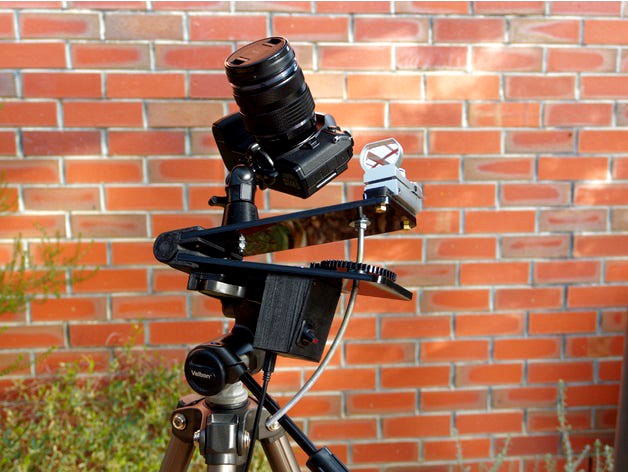
I desired a simple and reliable star tracker, that was also small enough to carry, particularly for hiking or travelling.
The use of the Arduino provides a lot of flexibility in gear and thread choice. Mine uses an M6 thread to drive the barn door.
You may need to adapt it to your tripod/camera mount. There's a 6.5mm (1/4) hole for the camera mount. I used a 3d printed base for a ball joint from an old monopod, bolted in with a 6mm bolt. The tripod mount is designed to fit my Vanguard tripod with foot dimensions of 10mm high, top 32.3mm square, base 42mm square.
There's a couple of potential improvements that could be made. The hinge could be redesigned to incorporate bearings (see update 19/06/17). The gear system could benefit from bearings as well. In a 'perfect' system, the main gear would rotate around a bearing, and the guide rod would be constrained by the gear. In this model (and most other barn door star trackers) the threaded rod constrains the main gear, and is itself constrained by the hole in the acrylic. As the hole in the perspex has to have some leeway for the threaded rod, this could result in vibration or oscillation as the rod and gear move around the hole.
This design includes a picatinny rail for mounting a sighting scope.
Electronics consists of an Arduino Nano (just the board - no riser pins), an illuminated switch, and a 5V BYJ48 stepper motor. Speed control is defined in the code, so just flick the switch to start tracking.https://youtu.be/23A9o62kssQ
I'm not going to draw a sketch for the electronics. I'll just list the wiring below. There's not much clearance in the case for wiring, so be neat. :D
Pin 12 -> switch -> ground
Pin 3 -> stepper IN1
Pin 4 -> stepper IN2
pin 5 -> stepper IN3
pin 6 -> stepper IN4
5V -> stepper positive
Ground -> stepper negative
5V -> switch LED (If you want an illuminated switch)
ground -> switch LED (If you want an illuminated switch)
The whole thing is powered over USB from a battery pack. In my case I'm using a 4AA Goal Zero power pack.
Fasteners used were:
10 x M5 countersunk. I cut mine down to the right length, but if you have options, then lengths should be around 6x12mm (picatinny rail and hinge) and 4x 25mm (tripod mount).
2x ~3mm screws, ~15mm long (to screw the control box to the tripod mount).
6x #4x12mm screws (for Nano enclosure and control box lid).
2x 3mm bolts, ~ 15-20mm long (for motor).
1x M6 bolt (for camera mount)
1x M6 threaded rod.
In terms of weight capability, the main factor is probably the acrylic panels and plastic rather than the gearing. I don't see any problems with mounting things up to 1.5KG on mine. If mounting heavier stuff, just be aware that the tripod and camera mount are plastic. In terms of gears, with a 5/1 gear ratio to the stepper and another ~3/1 in the barndoor, I suspect that there is no camera heavy enough to could stop the gears from turning.
Warning: Yes, you can rotate your camera around to tip it over the hinge. If you're concerned then figure out your balance point and cut the threaded rod a bit shorter than that.
Update: 19/6/2017
I have now developed a bearing hinge that uses a couple of 608 bearings (Roller skate bearings). The files for the bearing hinge are "Bearing Hinge Interior" and "Bearing Hinge Exterior". The bearings are clamped in place with a couple of M8 35mm bolts, with captive nuts in the Interior portion. There's 1mm clearance between the two sections, so make sure you don't overtighten the bolts. This design means that all of the bearings are captive, rather than just relying on a push-fit, and can centre the hinge components so that there is no rubbing anywhere between plastic.
Similar models
thingiverse
free

Creality CR- 10 Webcam Mount
...0 x 1.25", two washers and two nuts to be able to jam them into each other so they don't back out due to the vibrations.
thingiverse
free

Barn Door Tracker by RefreshingViews
...er shoe
finder shoe screw
electrickery
rca phono plugs
12v pwm regulator
project box
wiring, solder, heat shrink, connector block
thingiverse
free

Motorized barndoor tracker for astrophotography by elenhinan
...r
1x a4988 (or other stepper driver)
1x arduino nano
1x 1/4 inch 20 tpi screw for mounting camera
m3 screws for the laser pointer
thingiverse
free

GEEETech Prusa i3b Acrylic - Front Switch Box from Z-axis stepper mounts (L&R) by kafarn
...g my power switch to the front so i don't have to reach around and feel for the power switch just to turn the printer on/off.
thingiverse
free

Universal Tripod Quick Release Mount
...mera at all times and quickly switch between my camera and my iphone mount with the use of these d-rings:
https://amzn.to/39mekq4
thingiverse
free

SunPac Tripod Boot for Projector by Hefe4pres
...t printed slightly bigger than i wanted so a little sanding was necessary. if you do print maybe scale it down a few percentages.
thingiverse
free

Tripod mount for M6 bolt by miroxfin
...tripod mount for m6 bolt by miroxfin
thingiverse
for tripod with quick attach mounts. can be used for cameras or lights etc.
thingiverse
free

Z brace for migbot i3 (8mm acrylic frame) by Reddrop
...parts printed (in this orientation using supports)
→ 4x m3 16mm bolts and 4x m3 nut
→ around 800mm of m6 threaded rod
→ 8x m6 nut
thingiverse
free

Tripod quick release for Velbon 7000 and others by 2hot6ft2
... is 6.1mm
bolt hole diameter is 8.1mm
bolt hole depth is 9.6mm
i used a bolt i had laying around but a m6x10mm bolt should work.
grabcad
free

Bolt M6
...bolt m6
grabcad
threaded rod ( bolt m6 )
Tracker
turbosquid
$8

Tracker Knife
... model tracker knife for download as blend, dae, fbx, and obj on turbosquid: 3d models for games, architecture, videos. (1588741)
turbosquid
$1

Tracker Knife
... available on turbo squid, the world's leading provider of digital 3d models for visualization, films, television, and games.
3d_export
$5

solar tracker
...aterial : -arduino uno -2 step motor with driver -4 ldr sensor -some wires -small photovoltaiic pannel -buzzer -cnc laser machine
3d_export
$7

sci-fi injector or tracker
... can be tracker, use as you want. pbr 4k contain: blend (includes high poly)/ dae / fbx / obj / stl / glowing injector + box
3d_export
$10

Motion Tracker Aliens
...er out moving objects from stationary background and then displayed them on the monitor as a series of contours of probable loci.
3d_export
$5
single axis solar tracker stand
...single axis solar tracker stand
3dexport
3d_export
$60
grumman s-2 f tracker
...ining in service with other air arms into the 21st century. argentina and brazil are the last countries to still use the tracker.
3d_export
$19

Chevrolet tracker 2021
...pport ticket and request for that. we can convert 3d models to: .stl, .c4d, .obj, .fbx, .ma/.mb, .lwo/.lws, .3ds, .3dm, .dxf/.dwg
3d_export
$25
emergency power with solar tracker
...cker
3dexport
this is a tool used to distribute electricity during an emergency disaster, it is recommended to use sketchup 2019
3d_export
$15

M314 Motion Tracker Aliens
...ng objects from stationary background and then displayed them on the m314's monitor as a series of contours of probable loci.
Martin
3ddd
$1

Aston Martin
...aston martin
3ddd
aston martin
aston martin db8
3ddd
$1

ANDREW MARTIN
...andrew martin
3ddd
andrew martin
кресло фабрики andrew martin, коллекция triton chair
3d_export
$123

aston martin
...aston martin
3dexport
aston martin
3ddd
free

MARTIN
...martin
3ddd
blank d`ivoire
martin blank d`ivoire
lustrehttp://www.blancdivoire.com/lustres/2192-martin.html
3ddd
$1

aston martin
...aston martin
3ddd
спорткар aston martin
3ddd
$1

Светильники Martin
...светильники martin
3ddd
alien , martin
с матами.
3ddd
$1

Andrew Martin Dali
...ndrew martin , dali , martin
andrew martin dali
3ddd
free

Andrew Martin Douglas
...n , douglas , martin
andrew martin стол douglas
3ddd
$1

Andrew Martin / garcia
...andrew martin / garcia
3ddd
andrew martin
andrew martin garcia chair
3ddd
free

Andrew Martin / Carlotta
...andrew martin / carlotta
3ddd
andrew martin
кресло andrew martin / carlotta
Au
turbosquid
$10

Pain Au chocolat
...quid
royalty free 3d model pain au chocolat for download as on turbosquid: 3d models for games, architecture, videos. (1652051)
3ddd
$1

Kolarz RUBENS 0244.14.Au
...kolarz rubens 0244.14.au
3ddd
kolarz
kolarz rubens 0244.14.au люстра
3ddd
$1

Karman AU REVOIR светильник
...karman au revoir светильник
3ddd
karman
производитель karman, au revoir настольный декоративный светильник
turbosquid
$4

Powerboard AUS NZ
...odel powerboard aus nz for download as max, obj, fbx, and stl on turbosquid: 3d models for games, architecture, videos. (1475247)
turbosquid
$2

Pain au chocolat
... pain au chocolat for download as lwo, lxo, stl, obj, and fbx on turbosquid: 3d models for games, architecture, videos. (1644992)
turbosquid
free

schrank aus kifer.sit
... available on turbo squid, the world's leading provider of digital 3d models for visualization, films, television, and games.
3ddd
$1

Airship AU-30
...airship au-30
3ddd
дирижабль
аппарат в масштабе создан по чертежам
vray 2.0
3ddd
$1

Kolarz NISIDA 0378.84.3.Au
...kolarz nisida 0378.84.3.au
3ddd
kolarz
люстра nisida от kolarz
3ddd
$1

Kolarz NISIDA 0378.62.3.Au
...kolarz nisida 0378.62.3.au
3ddd
kolarz
бра серии nisida, фабрики kolarz
3ddd
$1

B&B Italia, VOL AU VENT
... vent
3ddd
b&b italia , vol au vent
длинна: 460 мм
ширина: 580 мм
высота: 840 мм
Star
3ddd
$1

Rolling Stars Antic Star
...rolling stars antic star
3ddd
rolling stars , вентилятор
rolling stars antic star
turbosquid
$2

Star Shuriken (Throwing Star)
... available on turbo squid, the world's leading provider of digital 3d models for visualization, films, television, and games.
design_connected
$18

Star
...star
designconnected
helen amy murray star computer generated 3d model. designed by murray, helen amy.
3d_ocean
$2

sea star
...sea star
3docean
game star sea star space star
this model is, normally poly model. use for games screen.
3d_export
$2

star gingerbread
...star gingerbread
3dexport
"star" gingerbread in the style of the movie star wars.
turbosquid
$10

STAR
...ar
turbosquid
royalty free 3d model star for download as max on turbosquid: 3d models for games, architecture, videos. (1338162)
turbosquid
$1

Star
...ar
turbosquid
royalty free 3d model star for download as c4d on turbosquid: 3d models for games, architecture, videos. (1564546)
3d_export
$5

star sword
...star sword
3dexport
star sword
3d_export
$5

Star building
...star building
3dexport
star building
3d_export
free

ikosaedr-star
...ikosaedr-star
3dexport
ikosaedr-star