Thingiverse
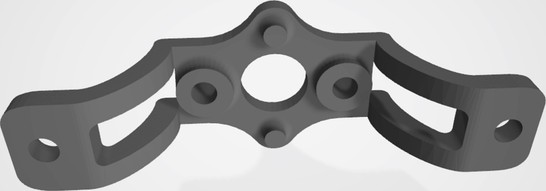
Star LED holder for Kawasaki Vulcan 750 Turn Signals by Morpheous85
by Thingiverse
Last crawled date: 3 years, 3 months ago
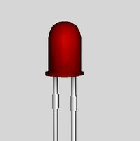
This is designed to hold a standard Star LED inside the stock turn signal housing. I use Cree XL-M RGBW LEDs. They have a maximum internal temperature of 150C. The recommended maximum currents below assume use of the Cree XL-M RGBW LED. The mounting surface is designed to minimize contact with the PCB to maximize heat transfer. The housing itself has a measured temperature rise of 7.5 C/W.
Here are a few videos comparing the LED with clear lens to the factory bulb and amber lens.https://youtu.be/gn7po60E8KM (LED vs Incandescent Amber)https://youtu.be/doI2Jd8qtY4 (LED Red vs Incandescent Amber)https://youtu.be/ceSAGbNMjWg (LED Red vs Amber)https://youtu.be/5WB9jIua1uw (Front vs Rear Test)
The mounting tabs use the lens holder screws to mount. The lens needs to be modified to allow for the thickness of the mounting tabs. This is a simple cutting of the screw mounting posts by the thickness of the mounting tabs. A Dremel cutting wheel should suffice.
It is recommended to use either Red lenses with the Red or White LED, Amber lenses with the White LED, or clear lenses with Red, Red + Green or White LEDs. If using Red or Amber lenses, it is recommended that the Warm White (3000 K) LEDs are used. Neutral may suffice, but Cool White have less then half the output in the red spectrum vs Warm White.
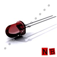
The LEDs are designed to be secured using two bolt/nut with plastic spacers/stand-offs added to prevent shorting the pads on the LEDs. One LED faces towards the lens, and the second LED faces away from the lens. The rearward one sits in the same location as the factory bulb filament, so it utilizes the factory reflector.
You should be able to run 700mA into the Red LEDs continuously (brake lights) in 41C heat for an internal temperature of 114C. Turn signals could be 700mA Red + 310 mA Green (9:4 ratio gives amber color approximation) with an internal temperature of 133C. This temperature assumes continuous use, where as turn signals are flashing. The actual internal temperature will be lower when flashing (approximately 124C). For rear running lights, the Red should be reduced to 70mA (1/10 of brake lights).
I wired the two LEDS in series for each color. I used 150/15 ohm for red (running/brake) and 300/30 ohm for green (running/turn). The 300 is omitted for the rear running. It is only used for the front. I used diodes to separate the signals coming in. I will add a schematic when I have it finalized.
When using in the front, you can run 450 mA into the White LEDs continuously (additional forward illumination) in 41C heat for an internal temperature of 113C. If you are using the White LEDs with a Red or Amber lens, the White LED can be run at 700 mA continuous in 41C heat for an internal temperature of 146C. While this is only 4C away from maximum, the duty cycle will result in a temperature estimate of 130C. DO NOT RUN WHITE LED CONTINUOUS AT THIS CURRENT LEVEL!!! Running lights are supposed to be 1/10th of brake/turn signal brightness by DOT standards.
To run white as running lights in the front, the circuit is a bit more complex, with a transistor and a time delay element, that shuts off the white whenever the turn signal is on, and leaves it off for 1-2 seconds. The circuit is a FQPF11P06 P-Channel MOSFET with the source at 12V and the drain connected to a pair of 22 ohm resistors. 22 ohms gives 450 mA at 15V. The gate is tied to ground with a 56K resistor and a 100 uF capacitor. This turns the transistor (and white LEDs) on by default. Both turn signals connect (through diodes) to the gate. Whenever either turn signal is used, the gate is driven to 12V and the transistor turns off all the white LEDs. After 1-2 seconds of turning off the turn signal, the 56K resistor fades the white LEDs back to full power. This can be seen in one of the videos.
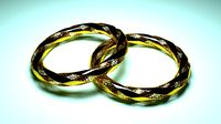
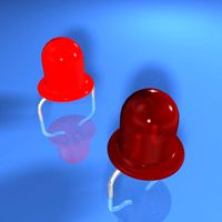
This piece should be printed with white material to minimize light absorption. However, the videos are done with black printed material so light absorption isn't a huge issue in practice. The picture of the two assemblies lit red shows one with a white printed piece and one with a black printed piece, both running at the same current level. If you can't see any difference, then don't worry about the color of the plastic! In my opinion, the white printed piece resulted in a more uniform light output.
Here are a few videos comparing the LED with clear lens to the factory bulb and amber lens.https://youtu.be/gn7po60E8KM (LED vs Incandescent Amber)https://youtu.be/doI2Jd8qtY4 (LED Red vs Incandescent Amber)https://youtu.be/ceSAGbNMjWg (LED Red vs Amber)https://youtu.be/5WB9jIua1uw (Front vs Rear Test)
The mounting tabs use the lens holder screws to mount. The lens needs to be modified to allow for the thickness of the mounting tabs. This is a simple cutting of the screw mounting posts by the thickness of the mounting tabs. A Dremel cutting wheel should suffice.
It is recommended to use either Red lenses with the Red or White LED, Amber lenses with the White LED, or clear lenses with Red, Red + Green or White LEDs. If using Red or Amber lenses, it is recommended that the Warm White (3000 K) LEDs are used. Neutral may suffice, but Cool White have less then half the output in the red spectrum vs Warm White.
The LEDs are designed to be secured using two bolt/nut with plastic spacers/stand-offs added to prevent shorting the pads on the LEDs. One LED faces towards the lens, and the second LED faces away from the lens. The rearward one sits in the same location as the factory bulb filament, so it utilizes the factory reflector.
You should be able to run 700mA into the Red LEDs continuously (brake lights) in 41C heat for an internal temperature of 114C. Turn signals could be 700mA Red + 310 mA Green (9:4 ratio gives amber color approximation) with an internal temperature of 133C. This temperature assumes continuous use, where as turn signals are flashing. The actual internal temperature will be lower when flashing (approximately 124C). For rear running lights, the Red should be reduced to 70mA (1/10 of brake lights).
I wired the two LEDS in series for each color. I used 150/15 ohm for red (running/brake) and 300/30 ohm for green (running/turn). The 300 is omitted for the rear running. It is only used for the front. I used diodes to separate the signals coming in. I will add a schematic when I have it finalized.
When using in the front, you can run 450 mA into the White LEDs continuously (additional forward illumination) in 41C heat for an internal temperature of 113C. If you are using the White LEDs with a Red or Amber lens, the White LED can be run at 700 mA continuous in 41C heat for an internal temperature of 146C. While this is only 4C away from maximum, the duty cycle will result in a temperature estimate of 130C. DO NOT RUN WHITE LED CONTINUOUS AT THIS CURRENT LEVEL!!! Running lights are supposed to be 1/10th of brake/turn signal brightness by DOT standards.
To run white as running lights in the front, the circuit is a bit more complex, with a transistor and a time delay element, that shuts off the white whenever the turn signal is on, and leaves it off for 1-2 seconds. The circuit is a FQPF11P06 P-Channel MOSFET with the source at 12V and the drain connected to a pair of 22 ohm resistors. 22 ohms gives 450 mA at 15V. The gate is tied to ground with a 56K resistor and a 100 uF capacitor. This turns the transistor (and white LEDs) on by default. Both turn signals connect (through diodes) to the gate. Whenever either turn signal is used, the gate is driven to 12V and the transistor turns off all the white LEDs. After 1-2 seconds of turning off the turn signal, the 56K resistor fades the white LEDs back to full power. This can be seen in one of the videos.
This piece should be printed with white material to minimize light absorption. However, the videos are done with black printed material so light absorption isn't a huge issue in practice. The picture of the two assemblies lit red shows one with a white printed piece and one with a black printed piece, both running at the same current level. If you can't see any difference, then don't worry about the color of the plastic! In my opinion, the white printed piece resulted in a more uniform light output.
Similar models
3dwarehouse
free

Canadian Dialight LED left turn signals
...ber #anytime #arrows #canadian #clear #dialight #explode #flip #green #led #left_turn #lenses #red #signals #traffic_signals #use
3dwarehouse
free

LED traffic signals
...als
3dwarehouse
from south pasadena. #12_inch #amber #ball #clear #explode #green #led #lens #red #signals #traffic_signals #use
3dwarehouse
free

LED 8 inch left turn signals
... #8_inch_arrows #amber #anytime #arrows #explode #flip #green #led #left_turn #lens #red #reflector #traffic_signals #use #yellow
thingiverse
free

Raspberry Pi Switched LED Nightlight
...istor
i've gone as high was 8 whites, or 6 reds powered from a 12v supply, but that's overkill for that small of a light.
thingiverse
free

LED rear stop light with turn signals for e-bike by 1MRF
...ls for e-bike by 1mrf
thingiverse
e-bike tail light with powerful leds with turn signals and brake light. bicycle saddle mount.
grabcad
free

Truck Amber Signal Light
...truck amber signal light
grabcad
4" truck, military, amber turn signal lamp.
led.
thingiverse
free

Led Light Array Controlled by a Potentiometer by 4612A
...iometer. it uses five 5mm leds and five 200 ohm resistors. it runs off an adruino uno. the potentiometer controls the five leds.
thingiverse
free

Raspberry Pi 40mm Fan Mount by Homwer
... fan
40mm fan grill
3x led 3mm
3x 56 ohm resistor
1x bc337 transisitor
4x m2,5x10mm spacer
8x m2,5x4mm screws
4x m2,5x16mm screws
grabcad
free

Flashing LED 9V Circuit
...flashing led 9v circuit
grabcad
9.22v flashing led circuit using 2n2222 npn transistor, 1k ohm resistor, and 1000uf capacitor
thingiverse
free

Extruder light (led) by hawkan
...h arm contains three 5mm white leds in series and a 150 ohm resistor. the extruder mount fits on the bolts on the wades extruder.

Vulcan
turbosquid
$69

Vulcan
... available on turbo squid, the world's leading provider of digital 3d models for visualization, films, television, and games.
3d_export
$25

Aston Martin Vulcan
...aston martin vulcan
3dexport
aston martin vulcan low poly with interior
turbosquid
$69

Vulcan Racing
... available on turbo squid, the world's leading provider of digital 3d models for visualization, films, television, and games.
turbosquid
$9

Vulcanic Axe
...odel vulcanic axe for download as png, 3ds, obj, fbx, and dae on turbosquid: 3d models for games, architecture, videos. (1257633)
turbosquid
$5

vulcan gun.gmax
... available on turbo squid, the world's leading provider of digital 3d models for visualization, films, television, and games.
3d_export
$19

M134 Vulcan Minigun PBR
...m134 vulcan minigun pbr
3dexport
3d model of the m134 vulcan minigun
turbosquid
$25

Fantasy Sword - Vulcan
... available on turbo squid, the world's leading provider of digital 3d models for visualization, films, television, and games.
turbosquid
$49

Seamless Vulcanic Black Stone
...ee 3d model seamless vulcanic black stone for download as max on turbosquid: 3d models for games, architecture, videos. (1355789)
turbosquid
$39

Barbecue Mousson Vulcan Max
...barbecue mousson vulcan max for download as max, obj, and fbx on turbosquid: 3d models for games, architecture, videos. (1174601)
turbosquid
$40

vulcanic island mountain landscape
... available on turbo squid, the world's leading provider of digital 3d models for visualization, films, television, and games.
Kawasaki
turbosquid
$50

Kawasaki Z650
...quid
royalty free 3d model kawasaki z650 for download as max on turbosquid: 3d models for games, architecture, videos. (1607697)
turbosquid
$30

Kawasaki Motors
...id
royalty free 3d model kawasaki motors for download as max on turbosquid: 3d models for games, architecture, videos. (1201907)
cg_studio
$10

Kawasaki ZX9R3d model
...ke zx9r motorcycle sportbike
.3ds .max - kawasaki zx9r 3d model, royalty free license available, instant download after purchase.
3d_export
$40

Kawasaki ZX9R 3D Model
...kawasaki zx9r 3d model
3dexport
bike speed kawasaki
kawasaki zx9r 3d model craf 8252 3dexport
turbosquid
$65

Kawasaki Ninja
... available on turbo squid, the world's leading provider of digital 3d models for visualization, films, television, and games.
3ddd
$1

Kawasaki Ninja
...рс
спортивный мотоцикл
kawasaki ninja
high poly модель
polys. - 579,000
verts. - 518,000
только vray материалы - без текстур
3d_export
$14

Kawasaki MeanMachine 3D Model
...eanmachine 3d model
3dexport
kawasaki mean machine motorcycle bike motorbike
kawasaki meanmachine 3d model zarday321 567 3dexport
3d_export
$5

Kawasaki Logo 3D Model
...saki logo 3d model
3dexport
kawasaki logo moto motrcycle parts motorcycle part
kawasaki logo 3d model dimitrithess 36724 3dexport
3d_export
$12

New kawasaki 3D Model
...new kawasaki 3d model
3dexport
new kawasaki 3d model vivek22922 54000 3dexport
cg_studio
$29

Kawasaki Ninja3d model
...inja3d model
cgstudio
.obj .max .fbx - kawasaki ninja 3d model, royalty free license available, instant download after purchase.
750
3ddd
$1

SMEG PX-750
...smeg px-750
3ddd
варочная панель , smeg
smeg px-750
turbosquid
$9

Flowerpot 750
...free 3d model flowerpot 750 for download as max, obj, and fbx on turbosquid: 3d models for games, architecture, videos. (1238161)
turbosquid
$249

GSXr 750
... available on turbo squid, the world's leading provider of digital 3d models for visualization, films, television, and games.
3ddd
$1

ELEYUS Into 52 750 IS
...nto 52 750 is
3ddd
вытяжка , eleyus
вытяжка eleyus, модель into 52 750 is
ширина - 52 см
3d_export
$14

Honda VF 750 3D Model
...honda vf 750 3d model
3dexport
honda vf 750 motorcycle
a medium poly high map model of a honda vf 750
3ddd
free

Стол журнальный Joker 750
... joker 750
3ddd
журнальный , круглый
огого обстановочка.
диаметр: 750 mm
высота: 500 mm
turbosquid
$14

Bushing 750 KV
... available on turbo squid, the world's leading provider of digital 3d models for visualization, films, television, and games.
3d_export
$39

Honda nr 750 3D Model
...honda nr 750 3d model
3dexport
motorcycle sport bike honda nr 750 high detailed model
honda nr 750 3d model 3dd 1327 3dexport
design_connected
$16

SAN PELLEGRINO Bottles 750 ml
...san pellegrino bottles 750 ml
designconnected
san pellegrino bottles 750 ml computer generated 3d model.
turbosquid
$39

750 Favo Lightstar Collection
...del 750 favo lightstar collection for download as max and fbx on turbosquid: 3d models for games, architecture, videos. (1163739)
Signals
archibase_planet
free

Signals
...signals
archibase planet
lift equipment elevator signals
elevator signals - 3d model for interior 3d visualization.
archibase_planet
free

Signal
...e planet
fire-extinguishing equipment fire-alarm fire signal
fire signal - 3d model (*.gsm+*.3ds) for interior 3d visualization.
turbosquid
$3

Signal
... available on turbo squid, the world's leading provider of digital 3d models for visualization, films, television, and games.
3ddd
free

Signal H-134
...signal h-134
3ddd
signal
стул signal h-134
3ddd
free

SIGNAL обеденная группа
...signal обеденная группа
3ddd
signal
обеденная группа signal loreto
3ddd
free

Signal q-088
...signal q-088
3ddd
signal , стул
кресло signal q-088
3ddd
$1

LN-SC Signal
...ln-sc signal
3ddd
стул , signal
стул ln-sc signal, польша
archive3d
free

Signals 3D Model
...ve3d
lift equipment elevator signals
elevator signals - 3d model for interior 3d visualization.
3d_export
$15

Signal Tower
...signal tower
3dexport
3ddd
$1

Berlin Signal
...al (польша)
высота: 105 см
размеры матраса: 200х160 см
материал: дерево (гевея), металл
цвет: дерево - белый, металл – чёрный
Turn
turbosquid
$60

TURN TURN
... available on turbo squid, the world's leading provider of digital 3d models for visualization, films, television, and games.
design_connected
$11

Turn
...turn
designconnected
seletti turn computer generated 3d model. designed by zambelli, alessandro.
3ddd
$1
Jorger Turn
... turn , смеситель
коллекция смесителей фирмы jorger, серия turn
3ddd
$1
joerger turn
...
joerger , смеситель
http://www.joerger.de/
коллекция turn
артикул 623,30,300
design_connected
$9
Turning desk
...turning desk
designconnected
atelier areti turning desk computer generated 3d model. designed by kerschbaumer, gwendolyn.
3ddd
$1

E-Turn
... скамейка
современная скамейка фирмы kundalini.
модель e-turn.
дизайнер brodie neil.
размеры: h 42 cm l 185 cm w 54 cm
design_connected
$16

Re-turned
...
photo-realistic 3d models of the re-turned table accessories from beller for 3d architectural and interior design presentations.
turbosquid
$15
Turn Ring
...rbosquid
royalty free 3d model turn ring for download as max on turbosquid: 3d models for games, architecture, videos. (1482401)
turbosquid
$15

turning torso
...quid
royalty free 3d model turning torso for download as 3dm on turbosquid: 3d models for games, architecture, videos. (1525931)
turbosquid
$6

RETURN OR TURN
...uid
royalty free 3d model return or turn for download as max on turbosquid: 3d models for games, architecture, videos. (1215382)
Led
3d_export
$5
led
...led
3dexport
the led is cut with all the parts.
3ddd
$1
Monacor / PARL56DMX / LED-320RGBW / LED-345RGBW / LED-300RGB
... прожектор
http://www.monacor.dk/
parl56dmx
led-320rgbw
led-345rgbw
led-300rgb
turbosquid
$10
LED
...led
turbosquid
free 3d model led for download as blend on turbosquid: 3d models for games, architecture, videos. (1691856)
3d_export
$5

led lamp
...led lamp
3dexport
led lamp, brightness animation
3ddd
free
leds-c4
...leds-c4
3ddd
leds-c4
современный торшер
3ddd
free
leds-c4
...leds-c4
3ddd
leds-c4
настольный лампа
turbosquid
$19
LED
... available on turbo squid, the world's leading provider of digital 3d models for visualization, films, television, and games.
turbosquid
$12
Led
... available on turbo squid, the world's leading provider of digital 3d models for visualization, films, television, and games.
turbosquid
free
LED
... available on turbo squid, the world's leading provider of digital 3d models for visualization, films, television, and games.
turbosquid
free
LED
... available on turbo squid, the world's leading provider of digital 3d models for visualization, films, television, and games.
Star
3ddd
$1

Rolling Stars Antic Star
...rolling stars antic star
3ddd
rolling stars , вентилятор
rolling stars antic star
turbosquid
$2

Star Shuriken (Throwing Star)
... available on turbo squid, the world's leading provider of digital 3d models for visualization, films, television, and games.
design_connected
$18

Star
...star
designconnected
helen amy murray star computer generated 3d model. designed by murray, helen amy.
3d_ocean
$2

sea star
...sea star
3docean
game star sea star space star
this model is, normally poly model. use for games screen.
3d_export
$2

star gingerbread
...star gingerbread
3dexport
"star" gingerbread in the style of the movie star wars.
turbosquid
$10

STAR
...ar
turbosquid
royalty free 3d model star for download as max on turbosquid: 3d models for games, architecture, videos. (1338162)
turbosquid
$1

Star
...ar
turbosquid
royalty free 3d model star for download as c4d on turbosquid: 3d models for games, architecture, videos. (1564546)
3d_export
$5

star sword
...star sword
3dexport
star sword
3d_export
$5

Star building
...star building
3dexport
star building
3d_export
free

ikosaedr-star
...ikosaedr-star
3dexport
ikosaedr-star
Holder
archibase_planet
free

Holder
...holder
archibase planet
holder toilet paper holder
holder paper n070712 - 3d model (*.gsm+*.3ds) for interior 3d visualization.
archibase_planet
free
Holder
...e planet
holder rack toilet paper holder
holder toilet roll n240715 - 3d model (*.gsm+*.3ds+*.max) for interior 3d visualization.
archibase_planet
free
Holder
...holder
archibase planet
pen holder support prop
pen holder - 3d model for interior 3d visualization.
archibase_planet
free
Holder
...holder
archibase planet
pole post holder
сhurch cross pole holder - 3d model for interior 3d visualization.
archibase_planet
free
Holder
...holder
archibase planet
holder bathroom ware
shower holder - 3d model (*.gsm+*.3ds) for interior 3d visualization.
archibase_planet
free

Holder
...oilet paper holder
holder paper devon&devon; time black n241113 - 3d model (*.gsm+*.3ds+*.max) for interior 3d visualization.
archibase_planet
free
Holder
...holder
archibase planet
holder hanger hanger for towel
holder 7 - 3d model (*.gsm+*.3ds) for interior 3d visualization.
archibase_planet
free
Holder
...holder
archibase planet
holder hanger hanger for towel
holder 3 - 3d model (*.gsm+*.3ds) for interior 3d visualization.
archibase_planet
free
Holder
...holder
archibase planet
holder towel rack towel-horse
holder - 3d model (*.gsm+*.3ds) for interior 3d visualization.
archibase_planet
free
Holder
...lder
archibase planet
holder hanger hanger for towel
holder towel n250912 - 3d model (*.gsm+*.3ds) for interior 3d visualization.