GrabCAD
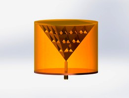
'Stack of Squares' Broadband Inverted Pyramid Antenna
by GrabCAD
Last crawled date: 1 year, 10 months ago
This is a model of a 'Stack of Squares' (4^2 ~ 3^2 ~ 2^2 ~ 1^2) Inverted Pyramid Broadband Antenna that I invented to see what unique shape antenna I could model that was well suited for 3D printing. This can be printed in a polymer and then sprayed with conductive paint, but is probably better off 3D printed in metal and then sintered for hardness.
This antenna is similar to the Sierpinski Fractal style of antenna, but is not based upon fractals, but merely squaring functions. The overall geometry is the longest wavelength and each successive lower tier represents a shorter wavelength (higher frequency). However the largest and smallest will dominate. Here's a good whitepaper on the subject : https://repository.wit.ie/3299/1/Design%20of%20Microwave%20Components%20using%20Direct%20Metal%20Laser%20Sintering.pdf
The circular enclosure is simply a method to keep the pyramid upright and level against the sides of the orange clear acrylic and flat across the top. The center conductor is soldered (not shown) with the base being a 2.54 mm or 0.1" thick piece of copper plate to serve as a ground plane. This is important to prevent coupling of the antenna onto the outside of the coax. I have also extruded the bases upward 0.5mm to merge with the intercepting points since the points touching each other would be too delicate to manufacture. Perhaps I could have fileted these but merging with an extrusion was easier at the time.
Overall dimensions of the top is 60mm x 60mm, so each pyramid is 15mm x 15mm. Overall height is 60mm, so each pyramid is 15mm tall. Diagonal corner edges are SQRT((60mm)^2 * (42.4264mm)^2) = 73.4847 mm = 7.35 cm which is about 1.02 GHz.
The smallest pyramids and inverted apertures are 15mm and are tuned to 4 times the frequency, so should be in the 4 GHz range. Also the triangular cutouts serve both as capture areas as well as image areas.
I hope to perform a 3D electromagnetic simulation and will post later the results. If anyone out there wants to take the initiative, then please let me know of your results. Thanks !
Similar models
grabcad
free

NSI-MI Technologies 2 ~ 18 Ghz Broadband Horn Antenna (BHA) with 15 dBi gain
... upon the familiar vivaldi waveguide.
this is the link : https://www.nsi-mi.com/products/antenna-products/broadband-horn-antenna
3dwarehouse
free

square pyramid fractal
...square pyramid fractal
3dwarehouse
6 step square pyramid fractal #fractal #pyramid #square
grabcad
free

Pasternack 1 GHz to 18 GHz Broadband Horn Antenna
...the pasternack pe9887-11 datasheet is here : https://www.pasternack.com/images/productpdf/pe9887-11.pdf a similar antenna is available from fairview microwave :...
grabcad
free

Wurth / Rosenberger SMA 4-hole Flange Waveguide 18 GHz connector
...g of this connector at 18 ghz (-3 db) with a length of 1.67 cm (full wavelength). note this does not include material thickness !
grabcad
free

Wurth / Rosenberger SMA 2-hole Flange Waveguide 18 GHz connector
...g of this connector at 18 ghz (-3 db) with a length of 1.67 cm (full wavelength). note this does not include material thickness !
thingiverse
free

1,3 GHz helical RHCP/LHCP antenna by sicarius
... the 1.3 ghz range
be sure to check the instructions!
update: the base had an error, fixed
update 2: added both polarisations
grabcad
free

Pasternack 1 GHz to 18 GHz (L, S, C, X, and Ka bands) Broadband Horn Antenna
...the pasternack pe9887-11 datasheet is here : https://www.pasternack.com/images/productpdf/pe9887-11.pdf a similar antenna is available from fairview microwave :...
grabcad
free

Planar Inverted 'F' Antenna (PIFA) 2.4 GHz
... this antenna is used for multiple wireless applications such as wifi, zigbee, bluetooth, &rfid in the 2.4 ~ 2.5 ghz ism band
3dwarehouse
free

Fractal Pentagon Pyramid
...fractal pentagon pyramid 3dwarehouse similar to my previous pyramids, except the base is a...
thingiverse
free

Sierpinski Pyramid Fractal with 1 iteration on each face. by Jimbotron
...nd printing at 100% scale. i did manage to print a 50% scale version but needed some super glue to reinforce the triangle bonds.
Broadband
design_connected
$13

Broadband Baskets
...broadband baskets
designconnected
broadband baskets computer generated 3d model.
turbosquid
$15

Broadband Router.lwo
... available on turbo squid, the world's leading provider of digital 3d models for visualization, films, television, and games.
cg_studio
$45

Linksys Broadband Router3d model
...studio
.max .3ds .lwo .obj - linksys broadband router 3d model, royalty free license available, instant download after purchase.
3d_ocean
$15
Wireless Broadband Network Router
... computer networking. similar to popular styles of wireless routers. this model was created in 3d studio max 2008 and has a ma...
3d_export
$10

MD300 sony ericsson Mobile broadband USB Modem 3D Model
...3d model
3dexport
usb modem md 300 sony erricson
md300 sony ericsson mobile broadband usb modem 3d model simondawa 38398 3dexport
3d_ocean
$9

4G Router
...3docean 3d 4g broadband connection internet models real router 3d,model,router,modelings,broadbandinternet ...
3d_export
$50

WiMAX Device 3D Model
...3dmax wimax device router routerboard database fiber ptic connection broadband wireless wifi protocol electronic networking it wimax device 3d...
3d_ocean
$10

Sleek Touchscreen Smart Phone
...sleek touchscreen smart phone 3docean broadband cellular digital mutli-touch popular shiny sleek smart phone wi-fi...
thingiverse
free

Ramsey SA7 Broadband RF Preamp Altoids Mount by cfaulkingham
...ramsey sa7 broadband rf preamp altoids mount by cfaulkingham
thingiverse
ramsey sa7 broadband rf preamp altoids plate mount.
thingiverse
free

Case for LNA RF Broadband Low Noise Amplifier Module UHF HF VHF
...vhf
thingiverse
case for lna rf broadband low noise amplifier module uhf hf vhf
https://www.aliexpress.com/item/32952717426.html
Inverted
turbosquid
free

Inverter
... available on turbo squid, the world's leading provider of digital 3d models for visualization, films, television, and games.
turbosquid
free

inverter model
...uid
royalty free 3d model inverter model for download as fbx on turbosquid: 3d models for games, architecture, videos. (1190633)
3d_export
$20

Technical Park Inverter
...technical park inverter
3dexport
technical park inverter (loop fighter)
turbosquid
$5

AC Inverter
... available on turbo squid, the world's leading provider of digital 3d models for visualization, films, television, and games.
3d_export
$5

Inverted Pentagram 3D Model
...inverted pentagram 3d model
3dexport
inverted pentagram
inverted pentagram 3d model roadkiller79 55651 3dexport
turbosquid
$36

DC-AC INVERTER
...model dc-ac inverter for download as max, obj, fbx, and sldpr on turbosquid: 3d models for games, architecture, videos. (1466093)
3d_export
$5

Iris Inverted Tiffany Pendant 3D Model
...tiffany pendant 3d model
3dexport
iris inverted tiffany pendant lamp
iris inverted tiffany pendant 3d model droog 100630 3dexport
3d_export
$5

inverter welding machine
...ene in the unreal, created in real sizes and ready to play. all textures are created in substance painter and have 4k resolution.
turbosquid
$4

Inverted Exclamation web icon
... available on turbo squid, the world's leading provider of digital 3d models for visualization, films, television, and games.
3d_export
$5

Dale Tiffany Garden Leaf Inverted Fixture Pendant 3D Model
...t
dale tiffany garden leaf inverted fixture lamp
dale tiffany garden leaf inverted fixture pendant 3d model droog 100623 3dexport
Pyramid
3d_export
free

pyramid
...pyramid
3dexport
pyramid for you
3d_export
free

conical pyramid
...conical pyramid
3dexport
beautiful pyramid
turbosquid
$300

Pyramid
...id
royalty free 3d model pyramid for download as max and obj on turbosquid: 3d models for games, architecture, videos. (1578437)
3d_export
$5

Pyramid
...pyramid
3dexport
turbosquid
$3

Pyramid
...yalty free 3d model pyramid for download as 3ds, max, and obj on turbosquid: 3d models for games, architecture, videos. (1198985)
turbosquid
$2

Pyramid
...lty free 3d model pyramid for download as 3ds, fbx, and blend on turbosquid: 3d models for games, architecture, videos. (1273189)
3d_export
$5

pyramid-headed
...pyramid-headed
3dexport
unfinished version of the pyramid head
turbosquid
$5

Pyramid
...ree 3d model pyramid for download as 3ds, obj, fbx, and blend on turbosquid: 3d models for games, architecture, videos. (1188226)
turbosquid
$40

pyramid
... available on turbo squid, the world's leading provider of digital 3d models for visualization, films, television, and games.
turbosquid
$25

pyramids
... available on turbo squid, the world's leading provider of digital 3d models for visualization, films, television, and games.
Antenna
archibase_planet
free
Antenna
...chibase planet
antenna aerial television antenna
antenna kathrein n090913 - 3d model (*.gsm+*.3ds) for exterior 3d visualization.
archibase_planet
free
Antenna
...antenna
archibase planet
satellite antenna
antenna 1 - 3d model (*.gsm+*.3ds) for exterior 3d visualization.
archibase_planet
free
Antenna
...antenna
archibase planet
equipment satellite antenna
antenna 2 - 3d model (*.gsm+*.3ds) for exterior 3d visualization.
archibase_planet
free
Antenna
...ntenna
archibase planet
satellite antenna equipment dish aerial
antenna 3 - 3d model (*.gsm+*.3ds) for exterior 3d visualization.
archibase_planet
free
Antenna
...antenna
archibase planet
satellite antenna dish dish aerial
antenna 4 - 3d model (*.gsm+*.3ds) for exterior 3d visualization.
archibase_planet
free
Antenna
...e planet
antenna dish dish aerial
antenna c-band satellite s180-g n210612 - 3d model (*.gsm+*.3ds) for exterior 3d visualization.
3d_export
$5

car antenna
...car antenna
3dexport
car antenna, antenna, car gadgets
turbosquid
$1

antenna
...rbosquid
royalty free 3d model antenna for download as blend on turbosquid: 3d models for games, architecture, videos. (1655786)
3d_export
free

Station with antenna
...station with antenna
3dexport
station with antenna
turbosquid
$5

Antenna
...id
royalty free 3d model antenna for download as max and fbx on turbosquid: 3d models for games, architecture, videos. (1381532)
Stack
3d_ocean
$12

Box Stacks
...n
barrel box box stack shards
this is model of box stack with texture that equipped with its shards around the box to add detail.
3ddd
$1

Triptych Stacks
...sa
triptych stacks
современный светильникhttp://curiousaandcuriousa.co.uk/index.php/home/chandeliers1/hayward-gallery1
3ddd
$1

Stacking D
...stacking d
3ddd
leucos
stacking
manufacturer leucos
designer rockwell group
3d_ocean
$5

Stack of Dollars
... realistic stack
ready to render! textured photorealistic dollars are animated. stack of dollars are falling down over and over…
3d_export
$5

dollar stack
...dollar stack
3dexport
turbosquid
$16

Stack of Wood
...quid
royalty free 3d model stack of wood for download as max on turbosquid: 3d models for games, architecture, videos. (1360320)
3d_ocean
$5

Money Stacks
... formats: c4d (textured) – obj (untextured) texture type: standard engine materials poly count per stack: 120 important: this ...
turbosquid
$5

stack machine
...lty free 3d model stack machine for download as ige and sldas on turbosquid: 3d models for games, architecture, videos. (1226834)
turbosquid
$19

Stack of Barrels
...3d model stack of barrels for download as blend, fbx, and obj on turbosquid: 3d models for games, architecture, videos. (1472525)
turbosquid
$6

Brick Stack
...y free 3d model brick stack for download as 3ds, max, and obj on turbosquid: 3d models for games, architecture, videos. (1239828)
Squares
turbosquid
free

Square
...squid
free 3d model square for download as max, obj, and stl on turbosquid: 3d models for games, architecture, videos. (1510355)
3d_export
$5

square table
...square table
3dexport
square table
turbosquid
$12

Square
...oyalty free 3d model square for download as max, obj, and fbx on turbosquid: 3d models for games, architecture, videos. (1294110)
3ddd
$1
Square Ottoman
...square ottoman
3ddd
пуф
square ottoman
turbosquid
$25

The Square
...ee 3d model the square for download as mat, max, dxf, and obj on turbosquid: 3d models for games, architecture, videos. (1186399)
3d_export
$65

square
...square
3dexport
simple rendering of the scene file
3d_export
$65

square
...square
3dexport
simple rendering of the scene file
3d_export
$65

square
...square
3dexport
simple rendering of the scene file
3d_export
$65

square
...square
3dexport
simple rendering of the scene file
3d_export
$65

square
...square
3dexport
simple rendering of the scene file