GrabCAD
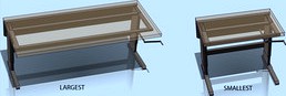
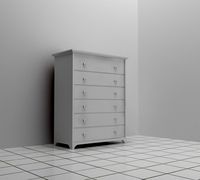
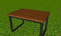
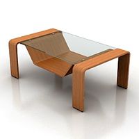
Sovella Existing Workbench (15 sizes)
by GrabCAD
Last crawled date: 7 years ago
Here is the existing table for everyone to download and use.
(This is NOT a contest entry)
In the Solidworks file it has "configurations" for every size that this table is made in. There are 15 sizes for the top and 10 sizes for the frame. One of the requirements of the challenge is that the movement mechanism works with most or all of the sizes.
At the top of the file tree select the "configuration" tab (two yellow cubes) and double click on the size you want.
The height is unrestrained, but if you want to set it open the "mates" at the bottom of the tree and unsuppress either "UPPER-HEIGHT" or "LOWER-HEIGHT"
Also posting a variety of sizes in Step files. Other Step table sizes are here
Sovella, existing workbench
Really thinking here that the optimum position for the hand crank is already defined by the existing table. Any deviation from that is going to be a negative. Underneath, on the side, it just doesn't work. This is a workbench, it has to be placed in any possible location and the only area of the table that is always accessible to reach a hand crank is the front side.
Strongly suggest that everyone look at the catalog of this table. (note the other languages besides English)
http://www.sovella.com/comEnglish/ProductCatalogue/
There are about a dozen accessories that attach to this table. You need to know the locations of all these to see if your design is going to interfere. Also if you look at the pictures on the challenge you can see the existing mechanism is pretty compact underneath leaving a lot of legroom and room for drawer cabinets, footrests, keyboard trays etc.
I don't think anyone has a monopoly on the various types of drive mechanisms since they are all simple machines first discovered by the 15th century. The concept is not as important as designing the concept to meet all of the requirements. If someone comes in first thing and declares they have sole use of a concept, and they do not develop it to meet all the requirements, then that detracts from the entire challenge.
Here are the ones I've seen and come up with so far. Everyone should feel free to use any of them.
1.Scissor jacks, one, two or four. Need shafts and gears to get the drive handle to proper position.
2.Crank to worm gear to shaft to rack and pinion on each end leg.
3.Crank to worm gear to shaft to each end with cable reels at end legs
4.Crank to cable winch (with brake), cables through pulleys to end legs
5.Manual hydraulic pump with 2 or 4 hydraulic cylinders.
6. Crank to worm gear to shafts to each end to gears on vertical screws at the end legs. This is the existing design.
To make cranking effort easier, stored energy is springs, most likely coil springs, compression and extension. Possibly torsion springs. Another possibility is gas springs (gas charged strut cartridges). With the wide range of weight and the 400mm travel, springs are going to be difficult but not impossible. Think garage doors (some have a coil spring under torsion) and hatch struts on cars. The potential weight differences between the smallest and largest table may call for different weight springs or some kind of spring adjustment.
(Edit)
7. Crank to shaft to 2 sprockets to chains to each end to sprockets to gears to vertical screws in end legs.
(Edit 12-25)
8. Hand crank to worm gear to transverse shaft to sprockets and chains in end legs
Similar models
grabcad
free

TS-32GZ370-5300, GEARED DC MOTOR
...-small-square-high-torque-worm-gearebox-right-angle-gear-370-motor-/321363227318?hash=item4ad2bdb2b6:g:pdeaaoswpgxvsw8l</a>
grabcad
free

Palacita Tubegun
...>
<br />the file aren't accurate but feel free to improve my design and please upload here your design my friend
grabcad
free

Keyshot 4 Toon Render
...uot; rel="nofollow" target="_blank">steel construction factory</a> by kuntay cem tezcan
<br />
grabcad
free

rotary and linier motion
...uot;nofollow" target="_blank">http://members.westnet.com.au/dps/pistonandrotation/rotationpiston.html</a>
grabcad
free

CNS ZN-15 36 CAL. RİFLİNG FULL ASSEMBİLİNG
...e.com/watch?v=vcw2mayopys</a>
<br />
<br />
<br />!!! videos of all the drawings of guns in this link !!!
grabcad
free

Plastic chair
...beer-glass--3" rel="nofollow" target="_blank">beer glass</a>
<br />chair and table: me ;)
grabcad
free

3D Monitor
...;a href="https://grabcad.com/library/uzi-pen-1" rel="nofollow" target="_blank">uzi pen</a>
grabcad
free

similar engine
...e/4" rel="nofollow" target="_blank">http://garethwashere.tumblr.com/page/4</a><br />video
grabcad
free

The Blue Angel
... /><br />likes are appreciated...<br />keep sharing fun and alive>>><br />download=like
grabcad
free

Круглый белый светодиод
...lt;a href="http://vk.com/simplab" rel="nofollow" target="_blank">http://vk.com/simplab</a>
Sovella
grabcad
free

Sovella, existing workbench
... chart
the original post with configurable sw file and other step sizes
http://grabcad.com/library/sovella-existing-workbench--1
grabcad
free

Table sovella simple workbench
...table sovella simple workbench
grabcad
table with worm system.
grabcad
free

Workbench for sovella
...grabcad
it has a heavy duty beat which when wound shall adjust the height of the bench.,, i just called it "erogoflex"
grabcad
free

workbench for Sovella
...grabcad
it has a heavy duty beat which when wound shall adjust the height of the bench.,, i just called it "erogoflex"
grabcad
free

Sovella Table 1
...ovella table 1
grabcad
its a simple design
and the threads can be decided according to the upward speed required by the person.
grabcad
free

Sovella Adjustable Height Table Concept
...sovella adjustable height table concept
grabcad
this is my table concept
grabcad
free

Sovella workbench
...eded is about 150 n
- approximate time for a complete movement is one minute
- chain can be covered with metal case plate / sheet
grabcad
free

Sovella workbench
...eded is about 150 n
- approximate time for a complete movement is one minute
- chain can be covered with metal case plate / sheet
cg_trader
free

Table sovella simple workbench
...table sovella simple workbench
cg trader
table with worm system. table adjusting height workbench 3d furniture
grabcad
free

Sovella Workbench
...gether with chain and sporcket.
handle is dismantling.
тransmission factor of mechanism allowed movements on table with 15mm/sec.
Workbench
3d_export
$10

workbench
...workbench
3dexport
workbench. in folder textures base color, height, metallic, normal, roughness. and model fbx.
3d_export
$5

mechanical workbench
...es, the mechanical hand has bones for animation, there are no textures since the standard colors are used, it does not load much.
turbosquid
$49

Moravian Workbench
... model moravian workbench for download as blend, fbx, and obj on turbosquid: 3d models for games, architecture, videos. (1284497)
turbosquid
$25

Old Workbench
...ee 3d model old workbench for download as blend, fbx, and obj on turbosquid: 3d models for games, architecture, videos. (1609131)
3d_export
$5

workbench
...workbench
3dexport
a simple old (or maybe not old, depending on the texture) vestak. in the archive fbx, obj, textures
turbosquid
$79

Workbench Roubo
... available on turbo squid, the world's leading provider of digital 3d models for visualization, films, television, and games.
turbosquid
$10

Workbench Helper
... workbench helper for download as 3ds, obj, fbx, 3dm, and skp on turbosquid: 3d models for games, architecture, videos. (1411448)
turbosquid
$1

Workbench Large
... available on turbo squid, the world's leading provider of digital 3d models for visualization, films, television, and games.
3d_export
$30

Folding workbench 3D Model
...g workbench 3d model
3dexport
workbench bench vice garage workshop shed tool
folding workbench 3d model pixelblock 43940 3dexport
turbosquid
$20

Old Workbench With Gears
...3d model old workbench with gears for download as max and fbx on turbosquid: 3d models for games, architecture, videos. (1633193)
Existing
turbosquid
$180

existing tank
... available on turbo squid, the world's leading provider of digital 3d models for visualization, films, television, and games.
turbosquid
$8

Suspended luminaire exist
...y free 3d model suspended luminaire exist for download as max on turbosquid: 3d models for games, architecture, videos. (1682341)
3ddd
$1

Sink
...sink 3ddd real existing , don't remember the...
3d_export
$5

drone - hubsan zino
...3d model of a drone - inspired by the existing drone "hubsan...
3d_ocean
$5

Design Pregnancy Test
...woman design innovation and easier to source than the existing design is too...
3d_export
$5

combined shelfbed
...elfbed
3dexport
open with sketchup 2017 or 2020. all files are zipped. blender and dae files are exist. use 7z to open archive.
3d_export
$5

chair
...nt, modern, stylish. delicate taste, well-matched colors. the texture used is the image that exists in the preview of this model.
3d_export
$5

Fancy Gloria Chair
...he materials by clicking on the objects. the cushions contain v-ray fur. you can remove it if you prefer to use a simple cushion.
3d_export
$39

Scary School
...se in various fields. it includes classrooms, toilets, gymnasiums, corridors, dining halls, dormitories, courtyards, etc. exists.
3ddd
$1

Loft table
...loft table
3ddd
журнальный
loft table
length 1200mm x width 750 x height 355mm
corona materials
exist files: 2012.max, obj
15
3d_export
$5

Iphone 15
...iphone 15
3dexport
apple iphone 15
3ddd
$1

Bed 15
...bed 15
3ddd
постельное белье
bed 15
design_connected
$13

Ella 15
...ella 15
designconnected
delightfull ella 15 computer generated 3d model.
design_connected
$27

Kilt 15
...kilt 15
designconnected
zanotta kilt 15 computer generated 3d model. designed by progetti, emaf.
design_connected
$22

Domino 15
...domino 15
designconnected
zanotta domino 15 computer generated 3d model. designed by progetti, emaf.
design_connected
$9

SMTV 15
...smtv 15
designconnected
maxalto smtv 15 computer generated 3d model. designed by citterio, antonio.
design_connected
$25

Docks 15
...docks 15
designconnected
gandia blasco docks 15 computer generated 3d model. designed by romero vallejo.
turbosquid
$23
![15 Ducks 15 Pond [Ducks and Set]](/t/13464970.jpg)
15 Ducks 15 Pond [Ducks and Set]
... available on turbo squid, the world's leading provider of digital 3d models for visualization, films, television, and games.
design_connected
$7

Bolla 15
...bolla 15
designconnected
gervasoni bolla 15 coffee tables computer generated 3d model. designed by michael sodeau.
3ddd
$1

Curtains 15
...curtains 15
3ddd
curtains 15
polys: 331066
other models:http://3ddd.ru/users/brast/models
Adjusting
3d_ocean
$7
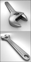
Adjustable Wrench
...adjustable wrench
3docean
adjustable wrench highly detailed wrench
highly detailed adjustable wrench.
3ddd
$1
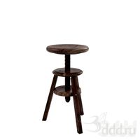
Adjustable Stool
...adjustable stool
3ddd
табурет
wooden adjustable stool.
3d_ocean
$20

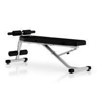
Adjustable Gym Bench
...st adjustable bench black equipement gym gymnastic indoor silver sport workout
3d model of black and silver adjustable gym bench.
3d_ocean
$20
Adjustable Gym Bench
...st adjustable bench black equipement gym gymnastic indoor silver sport workout
3d model of black and silver adjustable gym bench.
3d_ocean
$16

Adjustable Weight Bench
...arbell bench black equipement gym gymnastic indoor sport weight workout
3d model of black adjustable weight bench with a barbell.
turbosquid
$5

Adjustable wrench
...
royalty free 3d model adjustable wrench for download as fbx on turbosquid: 3d models for games, architecture, videos. (1313414)
3d_export
$5
adjustable tension lock
...adjustable tension lock
3dexport
adjustable tension lock
turbosquid
$1

Adjustable Wrench
...free 3d model adjustable wrench for download as obj and blend on turbosquid: 3d models for games, architecture, videos. (1446736)
turbosquid
$1

Adjustable Wrench
...y free 3d model adjustable wrench for download as c4d and fbx on turbosquid: 3d models for games, architecture, videos. (1379022)
3d_export
$5

Adjustable key
...adjustable key
3dexport
Height
turbosquid
$5
Height Stool
...ree 3d model height stool for download as blend, obj, and fbx on turbosquid: 3d models for games, architecture, videos. (1703076)
cg_studio
$20
Height Gauge3d model
...ndustrial height gauge tool indutsrial
- height gauge 3d model, royalty free license available, instant download after purchase.
turbosquid
$6
4.5 meters in height
...oyalty free 3d model 4.5 meters in height for download as max on turbosquid: 3d models for games, architecture, videos. (1213038)
turbosquid
$1
Counter Height Stool
... model counter height stool for download as obj, dae, and skp on turbosquid: 3d models for games, architecture, videos. (1318792)
turbosquid
$10
low height cabinet
...ow height cabinet for download as max, max, fbx, obj, and max on turbosquid: 3d models for games, architecture, videos. (1545300)
turbosquid
$5
Counter Height Bench
... available on turbo squid, the world's leading provider of digital 3d models for visualization, films, television, and games.
3ddd
free
Stanley furniture - Avalon heights
...stanley furniture - avalon heights
3ddd
stanley furniture
stanley furniture - avalon heights metal base empire writing desk
3d_ocean
$1

Maximum height sign
...ure applied. the object is ready to import and render in both formats. the model has been built to be able to subdivide flawle...
turbosquid
$20
Low height cabinet design
...y free 3d model low height cabinet design for download as max on turbosquid: 3d models for games, architecture, videos. (1402496)
turbosquid
$15
Atlantis Bar Height chair
...y free 3d model atlantis bar height chair for download as max on turbosquid: 3d models for games, architecture, videos. (1271123)
Table
3ddd
free
Table
...table
3ddd
table
table
archibase_planet
free
Table
...table
archibase planet
table glass-table round table glass table
table n240311 - 3d model (*.3ds) for interior 3d visualization.
archibase_planet
free
Table
...e
archibase planet
table dining-room table dinner table round table
table - 3d model (*.gsm+*.3ds) for interior 3d visualization.
3d_export
$5
table
...table
3dexport
table classic-table
archibase_planet
free
Table
...se planet
table glass table round table glass-table
table tonin habitat n280111 - 3d model (*.3ds) for interior 3d visualization.
archibase_planet
free
Table
...table
archibase planet
table dining-room table dinner table
table - 3d model (*.3ds) for interior 3d visualization.
archibase_planet
free
Table
...table
archibase planet
table coffee table glass table
table - 3d model (*.gsm+*.3ds) for interior 3d visualization.
archibase_planet
free
Table
...table
archibase planet
table glass-table coffee table
table - 3d model (*.gsm+*.3ds) for interior 3d visualization.
archibase_planet
free
Table
...table
archibase planet
table writing table office table
table - 3d model (*.gsm+*.3ds) for interior 3d visualization.
3d_ocean
$5
Table
...table
3docean
dining table furniture home kitchen table
simple wooden table.
Sizes
3d_export
$7
shoes size from 5 inch size to 11 inch
...shoes size from 5 inch size to 11 inch
3dexport
shoes design women model sizing from 5 inch to 11 inch
turbosquid
$15

Closet-small size
...
royalty free 3d model closet-small size for download as max on turbosquid: 3d models for games, architecture, videos. (1186088)
turbosquid
$5

Full size Futon
...id
royalty free 3d model full size futon for download as max on turbosquid: 3d models for games, architecture, videos. (1339638)
turbosquid
$4

mid size sword
...d
royalty free 3d model mid size sword for download as blend on turbosquid: 3d models for games, architecture, videos. (1160246)
turbosquid
$3

Mid size hammer
...
royalty free 3d model mid size hammer for download as blend on turbosquid: 3d models for games, architecture, videos. (1160647)
turbosquid
$19

Beaker 3 Sizes
...yalty free 3d model beaker 3 sizes for download as ma and obj on turbosquid: 3d models for games, architecture, videos. (1645955)
turbosquid
$20

Full Sized Bed
...d model full sized bed for download as max, 3ds, fbx, and obj on turbosquid: 3d models for games, architecture, videos. (1547542)
turbosquid
$45

King Size Bed
... available on turbo squid, the world's leading provider of digital 3d models for visualization, films, television, and games.
turbosquid
$15

Queen size bed
... available on turbo squid, the world's leading provider of digital 3d models for visualization, films, television, and games.
turbosquid
$14

Bed - Full Size
... available on turbo squid, the world's leading provider of digital 3d models for visualization, films, television, and games.