Thingiverse
Soldering Fume Extractor
by Thingiverse
Last crawled date: 4 years, 3 months ago
Soldering Fume Extractor
Introduction
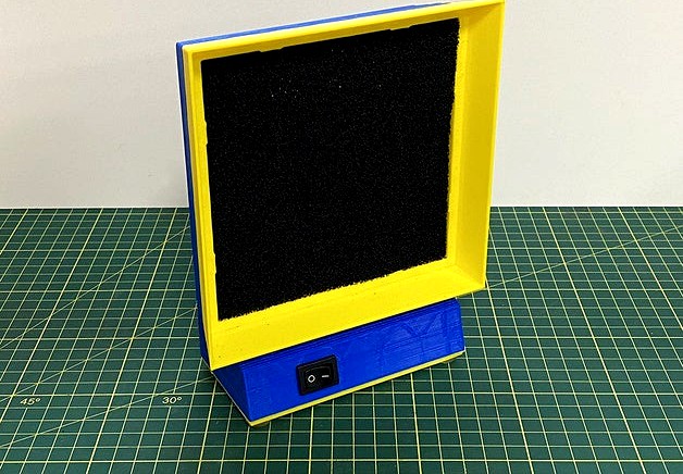
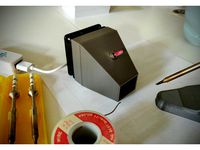
This is a 3D printed soldering fume extractor using a 12V PC case fan and USB-C PD board to allow 12V to be provided by a suitable USB-C charger instead of a 12V 'wall wart' adaptor. There are a lot of other 3D printed fume extractors out there but I didn't find any I quite liked, so now there is one more. Of course a lot of it was also about using parts I happened to have laying around.
Bill of Materials
Fasteners and Electronics
The following non-printed parts are required.
6 x Brass Hot Melt Inserts - M3x7
1 x USB-C PD Board
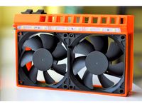
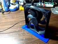
1 x 120x120x25mm 12V DC Fan
6 x M3x6mm Button Head Hex Screw
4 x M3 Thin Nut
4 x M3x30mm Button Head Hex Screw
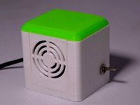
1 x 21x15mm SPST Rocker Switch
4 x Rubber Bumper Feet 10x2mm
1 x Activated Carbon Filter 130x130x10mm
1 x USB-PD Charger with 12V capability
1 x USB-C Cable
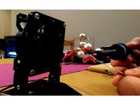
Most 120mm PC case fans should provide sufficient airflow, however it pays to set first. Power up the fan with the carbon filter in front of it (airflow should be front to back) and do a little soldering and ensure the fumes are pulled in.
Ensure the USB-PD charger you select is capable of providing 12V and sufficient current for the chosen fan. The USB-C cable should also be suitable for USB-PD usage.
Printed Parts
The following printed parts are required.
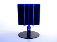
1 x Baffle
1 x Fan Housing
1 x Rear Panel
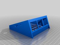
1 x Stand
1 x Base
I printed all but the base at 0.4mm layer height with a 0.8mm nozzle for speed. This resulted in a strong and fast print, if somewhat ugly. Because of the tolerances needed on the base piece for the USB-C PD board I printed the base at 0.2mm layer height with a regular 0.4mm nozzle. Of course, the entire print could be done with these settings too.
Supports are not be required. There are a few small bridges and overhangs but nothing major. Note that the rear panel and base of the fan housing and baffle are only 0.8mm thick. This was intentional to speed up printing, however take care not to break any of the parts before assembly.
Unsupported holes are closed up, so you will need to take a 3mm drill bit and open them up before using the parts. There is only a 0.4mm thickness to the filled part so it is easy to push the drill bit through. I printed mine in eSUN PLA+ however most filaments should be suitable.
Assembly
After printing insert two brass hot inserts into the fan housing and four into the stand. These can be easily pressed in with a soldering iron, if you want them to be really clean you can use one of these, let them go almost all the way in then turn the print upside down and press it on a flat surface.
Cut the connector off the fan and push the cable through the hole in the fan housing. Then push the fan itself into the fan housing, it should just be a tight friction fit. The screws used later are not to hold the fan in but rather to join the front to the back of the housing. Be sure not to pinch the cable.
Feed the cable through the hole in the stand, you can then screw the stand to the fan housing using 2 x M3x6mm screws. Place the baffle on the front and push through the four M3x30mm screws. Push the four M3 nuts into the positions on the rear panel and place the rear panel on and gently tighten the screws.
Take the base and insert the USB-C PD board. It helps to use a downward angle to line up the connector with the hole. Once lined up push the PCB down against the print. Ensure the lip at the back of the PCB is preventing it from sliding backwards when inserting a cable.
You will need to setup the USB PD board for 12V from start up. There is a small switch on the board, hold it down and insert the USB-C cable, connected to a PD capable charger. The LED on the board will cycle rapidly through its colours. Let go of the switch. You can then press the switch to manually cycle through the different colours, each of which represents a different voltage.
Press the button until the LED is red, this is the standard 5V setting. Press the switch again, it should switch to yellow (9V), then finally once more and it should switch to green (12V). Now hold the button until the light goes out, then replug the board. It should power up directly in 12V mode. Check this is the case with a multimeter before hooking up the fan. Note that there are quite a few variations of these USB PD boards so check the documentation for your specific one.
Before inserting the rocker switch into the stand you'll want to wire everything up, passing the wires needed through the front of the stand. I wired the switch inline with the positive fan cable and positive terminal on the USB PD board. Use your preferred method to hook up everything then screw the base to the stand, taking care to not pinch any wires.
After testing to ensure everything works you can install the rubber feet on the base. Finally insert the carbon filter into the front of the baffle, it should be a snug fit and stay in on its own. Switch it on and give it a test to see how it works. Happy soldering!
Introduction
This is a 3D printed soldering fume extractor using a 12V PC case fan and USB-C PD board to allow 12V to be provided by a suitable USB-C charger instead of a 12V 'wall wart' adaptor. There are a lot of other 3D printed fume extractors out there but I didn't find any I quite liked, so now there is one more. Of course a lot of it was also about using parts I happened to have laying around.
Bill of Materials
Fasteners and Electronics
The following non-printed parts are required.
6 x Brass Hot Melt Inserts - M3x7
1 x USB-C PD Board
1 x 120x120x25mm 12V DC Fan
6 x M3x6mm Button Head Hex Screw
4 x M3 Thin Nut
4 x M3x30mm Button Head Hex Screw
1 x 21x15mm SPST Rocker Switch
4 x Rubber Bumper Feet 10x2mm
1 x Activated Carbon Filter 130x130x10mm
1 x USB-PD Charger with 12V capability
1 x USB-C Cable
Most 120mm PC case fans should provide sufficient airflow, however it pays to set first. Power up the fan with the carbon filter in front of it (airflow should be front to back) and do a little soldering and ensure the fumes are pulled in.
Ensure the USB-PD charger you select is capable of providing 12V and sufficient current for the chosen fan. The USB-C cable should also be suitable for USB-PD usage.
Printed Parts
The following printed parts are required.
1 x Baffle
1 x Fan Housing
1 x Rear Panel
1 x Stand
1 x Base
I printed all but the base at 0.4mm layer height with a 0.8mm nozzle for speed. This resulted in a strong and fast print, if somewhat ugly. Because of the tolerances needed on the base piece for the USB-C PD board I printed the base at 0.2mm layer height with a regular 0.4mm nozzle. Of course, the entire print could be done with these settings too.
Supports are not be required. There are a few small bridges and overhangs but nothing major. Note that the rear panel and base of the fan housing and baffle are only 0.8mm thick. This was intentional to speed up printing, however take care not to break any of the parts before assembly.
Unsupported holes are closed up, so you will need to take a 3mm drill bit and open them up before using the parts. There is only a 0.4mm thickness to the filled part so it is easy to push the drill bit through. I printed mine in eSUN PLA+ however most filaments should be suitable.
Assembly
After printing insert two brass hot inserts into the fan housing and four into the stand. These can be easily pressed in with a soldering iron, if you want them to be really clean you can use one of these, let them go almost all the way in then turn the print upside down and press it on a flat surface.
Cut the connector off the fan and push the cable through the hole in the fan housing. Then push the fan itself into the fan housing, it should just be a tight friction fit. The screws used later are not to hold the fan in but rather to join the front to the back of the housing. Be sure not to pinch the cable.
Feed the cable through the hole in the stand, you can then screw the stand to the fan housing using 2 x M3x6mm screws. Place the baffle on the front and push through the four M3x30mm screws. Push the four M3 nuts into the positions on the rear panel and place the rear panel on and gently tighten the screws.
Take the base and insert the USB-C PD board. It helps to use a downward angle to line up the connector with the hole. Once lined up push the PCB down against the print. Ensure the lip at the back of the PCB is preventing it from sliding backwards when inserting a cable.
You will need to setup the USB PD board for 12V from start up. There is a small switch on the board, hold it down and insert the USB-C cable, connected to a PD capable charger. The LED on the board will cycle rapidly through its colours. Let go of the switch. You can then press the switch to manually cycle through the different colours, each of which represents a different voltage.
Press the button until the LED is red, this is the standard 5V setting. Press the switch again, it should switch to yellow (9V), then finally once more and it should switch to green (12V). Now hold the button until the light goes out, then replug the board. It should power up directly in 12V mode. Check this is the case with a multimeter before hooking up the fan. Note that there are quite a few variations of these USB PD boards so check the documentation for your specific one.
Before inserting the rocker switch into the stand you'll want to wire everything up, passing the wires needed through the front of the stand. I wired the switch inline with the positive fan cable and positive terminal on the USB PD board. Use your preferred method to hook up everything then screw the base to the stand, taking care to not pinch any wires.
After testing to ensure everything works you can install the rubber feet on the base. Finally insert the carbon filter into the front of the baffle, it should be a snug fit and stay in on its own. Switch it on and give it a test to see how it works. Happy soldering!
Similar models
thingiverse
free
Solder Fume Extractor 60mm Fan by reini1305
...v+)
usb cable
switch with a diameter of 6mm
i've chosen a 12v sunon fan which will happily run with 5v from a usb power bank.
thingiverse
free
Soldering Fume Extractor + LED Strip Mount by shreeyam
...aded inserts (but not necessary - the 80mm fans are pressed in well enough), two switches, and a power jack (arduino style, 12v).
thingiverse
free

Soldering fume extractor by gumslone
...b/59hirn) and 4 m3 screws to hold the fan also you'll need an activated coal filter which can be placed inside the enclosure.
thingiverse
free
Solder Fume Extractor w/switch by charliejgallo
...me extractor for 120mm fan (original https://www.thingiverse.com/thing:17086)
added switch, hole for cable and bigger side vents
thingiverse
free
120mm Fan Stand by MKGort
... usb exhaust fan. i use this one as a fume extractor for soldering. this should be compatable with any 120mm computer case fan.
thingiverse
free
Mini Solder Fume Extractor by gmelenka
...ue to adhere the carbon filter to one of the sliding panels.
in the future i may scale this model up to accommodate an 80mm fan
thingiverse
free
Fume Extractor V2 by ctheroux
...l wires
you also need a 12v power adapter with a 5.5 x 2.1 mm plug to power it.
you should not need support material to print it.
thingiverse
free

Defumer - Solder Fume Extractor by kleingeist
...outube.com/watch?v=to5gzc_jx_4
parts needed:
24 v fan 120mm x 25mm
24 v power supply
5,6mm female plug
m8 x 30 screws
flip switch
thingiverse
free
Solder fume extractor by kannya
...
solder fume extractor with switch and power plug.
useful tool for my workshop.
fan dimensions: 80 x 80 mm (holes 4xm4 72x72 mm)
thingiverse
free

Solder Fume Extractor by Malmstromen
...e fan cables through the spacing in the grate.
if you want you can use m4 screws to secure the case, fan and grate, i didn't.
Fume
turbosquid
$5

Tosato Fume
... available on turbo squid, the world's leading provider of digital 3d models for visualization, films, television, and games.
turbosquid
$4
Garis Stool Fume
... available on turbo squid, the world's leading provider of digital 3d models for visualization, films, television, and games.
turbosquid
$10
Chandelier IDL 359-4S FUME
... available on turbo squid, the world's leading provider of digital 3d models for visualization, films, television, and games.
turbosquid
$3
Door Handle Interior, Fumed Brass
...rior, fumed brass for download as max, max, 3ds, fbx, and obj on turbosquid: 3d models for games, architecture, videos. (1539559)
3ddd
$1

Люстра Alicante Fume / PL4 - Euroluce Lampadari
...ик из хромированного металла и дымчатого хрустального стекла. модель рассчитана на четыре галогенные лампы макс. мощностью 40 вт.
archive3d
free
Hood 3D Model
...hood 3d model archive3d fume hood laboratory equipment laboratory fume hood - 3d model...
3d_export
$10

Burberry Cologne 3D Model
...3dexport perfume cologne burberry fragrance scent bottle spray fume fume burberry cologne 3d model riteoff 7042...
3d_export
$39

Matches 3D Model
...3dexport matches fire smoking cigar cigarette hearth oven stove fume phoenix photoreal vray obj fbx matches 3d model sbgwolf...
3d_export
$5

Fire puff 002 3D Model
...3dexport fire puff explosion flame spark hot heat render fume gas smoke fire puff 002 3d model dreamkasztni 52818...
3ddd
$1

ALABASTRI DI REX DECORO PUZZLE
...фирмы rex, коллекция alabastri 1) ambra 2) bamboo 3) fume 4) madreperla 5) miel 6) smeraldo 7)...
Extractor
turbosquid
$35
Extractor
... available on turbo squid, the world's leading provider of digital 3d models for visualization, films, television, and games.
3d_export
$5
kitchen extractor
...kitchen extractor
3dexport
extractor hood for kitchen in stainless steel with blue tempered glass, very modern.
3ddd
free

Extractor Bosch DWB098E50
...extractor bosch dwb098e50
3ddd
вытяжка , bosch
extractor bosch dwb098e50
3ddd
free
Teka - Extractor hood
...teka - extractor hood
3ddd
teka , вытяжка
teka - extractor hood
turbosquid
$1
Extractor cupboard
...
royalty free 3d model extractor cupboard for download as max on turbosquid: 3d models for games, architecture, videos. (1161308)
turbosquid
$30
Lock extractor
... available on turbo squid, the world's leading provider of digital 3d models for visualization, films, television, and games.
turbosquid
free
air extractor
... available on turbo squid, the world's leading provider of digital 3d models for visualization, films, television, and games.
turbosquid
$59
Vehicle Exhaust Extractor
...3d model vehicle exhaust extractor for download as ma and fbx on turbosquid: 3d models for games, architecture, videos. (1689744)
turbosquid
$29
Liquid Liquid Extractor
... available on turbo squid, the world's leading provider of digital 3d models for visualization, films, television, and games.
turbosquid
$15
Bosch Extractor Modern
... available on turbo squid, the world's leading provider of digital 3d models for visualization, films, television, and games.
Soldering
3d_export
$6

Solder toy
...solder toy
3dexport
solder toy arnold render
3d_export
$6
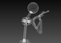
Automatic soldering machine
...automatic soldering machine
3dexport
automatic soldering machine
turbosquid
$10
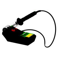
Solder Tools
...rbosquid
royalty free 3d model solder tools for download as on turbosquid: 3d models for games, architecture, videos. (1624226)
turbosquid
$1
Solderer simple
...squid
royalty free 3d model solderer simple for download as on turbosquid: 3d models for games, architecture, videos. (1171836)
turbosquid
$2
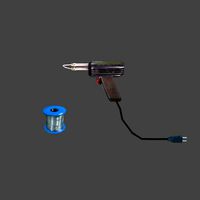
tin for soldering
...free 3d model tin for soldering for download as blend and fbx on turbosquid: 3d models for games, architecture, videos. (1689841)
turbosquid
$1
Soldering Iron
...ty free 3d model soldering iron for download as obj and blend on turbosquid: 3d models for games, architecture, videos. (1447146)
3d_export
$15

Solder 3D Model
...model 3dexport solder fusible metal alloy join melt melting soldering iron electronic gun alloys tin lead electrical wire coil...
turbosquid
$14

Soldering iron
...d model soldering iron for download as 3ds, max, obj, and fbx on turbosquid: 3d models for games, architecture, videos. (1389924)
turbosquid
$13
Soldering station
...el soldering station for download as blend, fbx, obj, and stl on turbosquid: 3d models for games, architecture, videos. (1552016)
turbosquid
$5
Steel solder
... available on turbo squid, the world's leading provider of digital 3d models for visualization, films, television, and games.