Thingiverse
Smoother Board mounts for Tevo Little Monster by robertwallace
by Thingiverse
Last crawled date: 4 years, 4 months ago
The 8-diode smoother boards are very effective at removing the "salmon skin" printing artifact from some delta printers - in particular, the Tevo Little Monster. They're very easy to install, and usually come with the jumper cable to connect them inline between the control board and the stepper motor.
One unfortunate side effect with the designer's choice of diodes is the amount of heat they dissipate - the board can get up to 80 degrees C, even with the motors idle (but powered.) I didn't want to stuff 4 of these heat producers inside the already-crowded space occupied by the Tevo's control board. I had also heard that the boards were more effective if they were connected closer to the motor. Though I have no evidence that it's true, I decided that I'd prefer mine to be installed that way and designed these smoother board mounts for the Tevo steppers.
They worked very well, but my first versions, in PLA, didn't do very good. That close to 80 degrees C, PLA gets a little, well, loose. I changed to PETG and re-sized them to account for PETG shrinkage and stretch, and these worked without getting soggy.
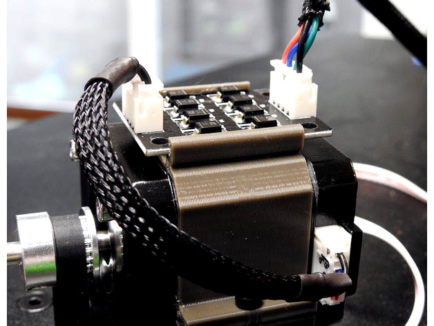
The mount is installed from the back of each motor, wraps around the motor and is cinched with an M3x10 screw. Orient them with the board slots pointing up for the axis motors and down for the extruder motor. Install the mounts before inserting the boards.
Unfortunately, the motor bracket screws keep this from being easy and for the axis motors next to the power box, you'll have to unscrew the power box, move it a little out of the way, install the mounts from the back of each motor and put the power box back in place. Tighten the mounts (the screwblocks may not meet - don't overtighten), slide the boards into the slots, and attach the modified cables. The mount covers snap into place. Route each connector's cable out an appropriate opening in the cover.
The extruder stepper motor is a smaller motor and there is a separate mount and cover for that stepper.
These mounts and covers were mostly a vanity project for me (notice I used braided cable sleeve entirely for appearance) - I don't expect them to have a broad appeal, since relocating the smoother boards to the motors requires cutting cables, exchanging the Tevo stepper motors' 6-pin connectors and the 4-pin connectors on the included jumper and soldering wires back together. I don't include instructions to do this because, while I knew what I was doing, explaining it to someone else would require me to make too many assumptions about the technical skill of strangers. I decided that if you know what you're doing, you don't need me telling you. And if you don't, you should just put the boards in the controller's case, as originally intended. They work there just fine, after all. [but in a nutshell: the signal path on the smoother board stays on the same side of the board from input to output - not on the same pin number. The way the sockets are keyed, pin 1 on the input puts the signal on pin 4 on the output. (Note the wire colors on the connected boards in the photos.) Also, the board doesn't "care" which connector you use for input or output.]
One unfortunate side effect with the designer's choice of diodes is the amount of heat they dissipate - the board can get up to 80 degrees C, even with the motors idle (but powered.) I didn't want to stuff 4 of these heat producers inside the already-crowded space occupied by the Tevo's control board. I had also heard that the boards were more effective if they were connected closer to the motor. Though I have no evidence that it's true, I decided that I'd prefer mine to be installed that way and designed these smoother board mounts for the Tevo steppers.
They worked very well, but my first versions, in PLA, didn't do very good. That close to 80 degrees C, PLA gets a little, well, loose. I changed to PETG and re-sized them to account for PETG shrinkage and stretch, and these worked without getting soggy.
The mount is installed from the back of each motor, wraps around the motor and is cinched with an M3x10 screw. Orient them with the board slots pointing up for the axis motors and down for the extruder motor. Install the mounts before inserting the boards.
Unfortunately, the motor bracket screws keep this from being easy and for the axis motors next to the power box, you'll have to unscrew the power box, move it a little out of the way, install the mounts from the back of each motor and put the power box back in place. Tighten the mounts (the screwblocks may not meet - don't overtighten), slide the boards into the slots, and attach the modified cables. The mount covers snap into place. Route each connector's cable out an appropriate opening in the cover.
The extruder stepper motor is a smaller motor and there is a separate mount and cover for that stepper.
These mounts and covers were mostly a vanity project for me (notice I used braided cable sleeve entirely for appearance) - I don't expect them to have a broad appeal, since relocating the smoother boards to the motors requires cutting cables, exchanging the Tevo stepper motors' 6-pin connectors and the 4-pin connectors on the included jumper and soldering wires back together. I don't include instructions to do this because, while I knew what I was doing, explaining it to someone else would require me to make too many assumptions about the technical skill of strangers. I decided that if you know what you're doing, you don't need me telling you. And if you don't, you should just put the boards in the controller's case, as originally intended. They work there just fine, after all. [but in a nutshell: the signal path on the smoother board stays on the same side of the board from input to output - not on the same pin number. The way the sockets are keyed, pin 1 on the input puts the signal on pin 4 on the output. (Note the wire colors on the connected boards in the photos.) Also, the board doesn't "care" which connector you use for input or output.]