Thingiverse
SmartRap modified Base Plate variations by SkyRider
by Thingiverse
Last crawled date: 4 years, 4 months ago
I had a lot of trouble getting the 0.5 version of the base plate printed. I tried sending off to ShapeWays and Ponoko both of which complained of wall thickness problems at the bearing pole and at the filament feed blocks. This is my humble and crude attempt at a fix. The holes for the filament and the bearing pole do require you to drill them out (I could not be sure what screw sizes would work so I didn't make them too large). I also left off the T-Slot at the top of the larger filament guide block (what is that for, BTW?).
An improvement to this would be to make the bearing movable and spring loaded to allow you to adjust the compression on the passing filament. It's also a prelude to being able to handle 3mm filament when the time comes. Any input would be much appreciated. This printed on my Solidoodle with .3mm resolution without incident.
UPDATE: I added a version with the bearing supports embedded. I will shortly add one more part that effectively reduces the parts count to 11.
UPDATE (again): In staying faithful to Serge's design, I put the T-Slot back in the latest version of this thing, but I've left all the other versions there to allow you to choose and do your own evolution.
UPDATE (yet again): It just bothered me that the bearing for the extruder was on a fixed mount and that it could not withstand the forces on it too much, so I cobbled this crude modification. The bearing mount is now its own part. Insert a small spring between it and the LM8UU bearing mount and pass an M2.5 or M3 or equivalent long screw with a nut on the bearing mount. If you use a screw slightly larger than the hole there, you will tap the hole and be able to adjust the tension on the filament and support multiple filament sizes. You might need to superglue the nut on the bearing mount to handle the forces being applied. If anyone has any ideas, please pass them along. Another idea is to put a spring on either side of the bearing mount and put a small washer and nut on the OTHER side of the bearing mount allowing the bearing mount to be under tension but also 'float' in its slot, which should help cushion some of the forces against the mount.
Printing note: So I found I made 2 small errors (ok, not that small for some). First, if you look at the versions with the build in mounts, you will see 2 holes have disappeared. I'll need to put those back in at some point. The second error is in the protrusion for the filament that has the T-slot in it. I will need to cut off a piece of it at the top of the circle where it is to allow my bearing to fit. To get your bearing to sit, file a little of the pillar for it and with a piece of flat stock (like a paint stirrer), hammer in the bearing. Once in, it will never move again as it is effectively press fit. Finally, if you are worried that the layers are put down in the Z-axis and cannot withstand tensile forces, get some LIQUID superglue and slather it all over the surface of this thing and let it cure overnight. The glue will make a tough shell that also will hold all the layers fast. If it works for my model rockets, it works for this.
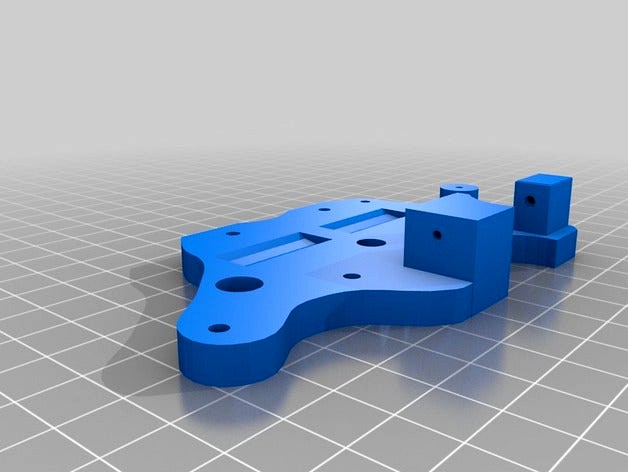
Build Update: A photo of the assembled base is included here and you can see the base plate and the Y plate together. Obviously, I don't intent to make my bed that big, but I know that if I wanted to, I could.
Final Update: In response to one request, I re-added the missing 2 holes I had inadvertently covered. On my print, I could still see their outline (I print ABS only) so I had drilled mine out. In this I put in 4mm holes. If they are narrow, simply widen them with your trusty drill.
An improvement to this would be to make the bearing movable and spring loaded to allow you to adjust the compression on the passing filament. It's also a prelude to being able to handle 3mm filament when the time comes. Any input would be much appreciated. This printed on my Solidoodle with .3mm resolution without incident.
UPDATE: I added a version with the bearing supports embedded. I will shortly add one more part that effectively reduces the parts count to 11.
UPDATE (again): In staying faithful to Serge's design, I put the T-Slot back in the latest version of this thing, but I've left all the other versions there to allow you to choose and do your own evolution.
UPDATE (yet again): It just bothered me that the bearing for the extruder was on a fixed mount and that it could not withstand the forces on it too much, so I cobbled this crude modification. The bearing mount is now its own part. Insert a small spring between it and the LM8UU bearing mount and pass an M2.5 or M3 or equivalent long screw with a nut on the bearing mount. If you use a screw slightly larger than the hole there, you will tap the hole and be able to adjust the tension on the filament and support multiple filament sizes. You might need to superglue the nut on the bearing mount to handle the forces being applied. If anyone has any ideas, please pass them along. Another idea is to put a spring on either side of the bearing mount and put a small washer and nut on the OTHER side of the bearing mount allowing the bearing mount to be under tension but also 'float' in its slot, which should help cushion some of the forces against the mount.
Printing note: So I found I made 2 small errors (ok, not that small for some). First, if you look at the versions with the build in mounts, you will see 2 holes have disappeared. I'll need to put those back in at some point. The second error is in the protrusion for the filament that has the T-slot in it. I will need to cut off a piece of it at the top of the circle where it is to allow my bearing to fit. To get your bearing to sit, file a little of the pillar for it and with a piece of flat stock (like a paint stirrer), hammer in the bearing. Once in, it will never move again as it is effectively press fit. Finally, if you are worried that the layers are put down in the Z-axis and cannot withstand tensile forces, get some LIQUID superglue and slather it all over the surface of this thing and let it cure overnight. The glue will make a tough shell that also will hold all the layers fast. If it works for my model rockets, it works for this.
Build Update: A photo of the assembled base is included here and you can see the base plate and the Y plate together. Obviously, I don't intent to make my bed that big, but I know that if I wanted to, I could.
Final Update: In response to one request, I re-added the missing 2 holes I had inadvertently covered. On my print, I could still see their outline (I print ABS only) so I had drilled mine out. In this I put in 4mm holes. If they are narrow, simply widen them with your trusty drill.